Advertisement
Available languages
Available languages
Quick Links
Advertisement

Subscribe to Our Youtube Channel
Related Manuals for Joy Sport Basic Pro


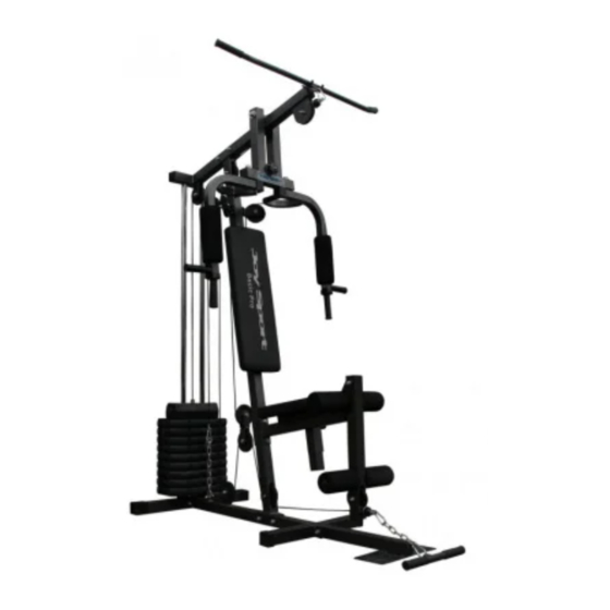
Summary of Contents for Joy Sport Basic Pro
- Page 1 HANDLEIDING Joy Sport Basic Pro...
-
Page 2: Geachte Klant
Deze garantie geldt gedurende 12 maanden voor elke fabricagefout aan uw JOY SPORT product die door een JOY SPORT dealer werd verkocht. Wanneer u garantie claimt bied JOY SPORT de mogelijkheid om naar eigen goeddunken het defecte apparaat of het betreffende onderdeel te herstellen of te vervangen. - Page 3 Onderdelen overzicht.
- Page 4 Onderdelenlijst. Naam en Specificatie Aantal. NR. Naam en Specificatie Aantal. Hoofdframe Plastic bus Gewichtsgeleiders Ronde busje Linker Frame Afdichtdop (50 mm) Rechter Frame Rubberen bescherming Gewichtspen Hand pijp Bovenste gewichtplaat Gewichtsstang Gewichtsplaat Afdichtdop (38 mm) Rubber dopje Verticaal frame Horizontaal frame M10 * 45mm Zit frame M12 * 75mm...
- Page 5 STAP 1 1. Plaats de rubberen bescherming (42) op het linker frame (3). 2. Plaats de gewichtgeleider (2) in het linker frame (3). 3. Monteer het hoofdframe (1) vast aan het linker frame (3). 4. Monteer het verticale frame (10) vast aan het hoofdframe (1).
- Page 6 STAP 2 1. Plaats de rubberen dop (9) over de gewichtgeleiders (2). 2. Schuif nu eerst de 7 gewichtsplaten (8) Bevestig daarna de gewichtspen (5) zoals aangegeven op de tekening hieronder en plaats daarna de bovenste gewichtsplaat (6) over de gewichtsgeleider (2). 3.
- Page 7 STAP 3 1. Monteer de 50mm afdichtdoppen (41) in het horizontale frame (12). 2. Monteer het horizontale frame (12) op het verticale frame (10) en monteer de gewichtsgeleiders (2) in het horizontale frame (12) zoals aangegeven op de tekening hieronder. 3.
- Page 8 STAP 4 1. Monteer de 50mm afdichtdoppen (41) in de beencurl (14). 2. Monteer het zit frame (13) op het verticale frame (10) Gebruik hiervoor M10*75mm (50) , M10 borgmoeren (63) en M10 ringen (68) zoals aangegeven in de tekening hieronder. 3.
- Page 9 STAP 5 1. Monteer de 50mm afdichtdoppen (41) in de steunarm butterfly (15). 2. Monteer de bussen (71) in de steunarm butterfly (15) zoals aangegeven op de foto hieronder. STAP 6 1. Monteer de steunarm butterfly (15) op het horizontale frame (12) gebruik hiervoor de pen (46) en de bussen (71), ringen (65 en borgmoeren (61) zoals aangegeven in de tekening hieronder.
- Page 12 USER MANUAL Joy Sport Basic Pro...
-
Page 13: Dear Customer
Dear customer, We want to thank you for having chosen a JOY SPORT product, and wish you a lot of fun and success during training with your JOY SPORT exercisers. Please note and follow the enclosed safety and assembly instructions carefully. - Page 14 Onderdelen overzicht.
-
Page 15: Part List
Part list. Name and spec. Pcs. Name and spec. Pcs. Main base Plastic bushing Guide rod 1’’ Round end cap Left base 50mm Square end cap Right base Rubber end cap Selector shaft Handle pipe Top plate Pin for weight stack Weight stack 38mm Square end cap Rubber dount... - Page 16 STEP 1 1. Place rubber cap (42) into both ends of left base (3). 2. Insert guide rods (2) to left base (3). 3. Attach main base (1) to left base (3) fasten all bolts by using tool. 4. Attach verticle beam (10) to mainbese (1).
- Page 17 STEP 2 1. Attach the rubber dount (9) into the guide rod (2). 2. Slide the weight plate (8) and top plate (6) over guide rod (2). Groove for selector pin on weight plates should face down. 3. Install 1’’ round bushing (38) into the selector shaft (5) with pin (47) then attach the selector shaft (5) into the top plate (6).
- Page 18 STEP 3 1. Place 50mm square cap (41) into both ends of top cross beam (12). 2. Attach top cross beam (12) onto the verticle beam (10) from top side and connect the guide rods (2) to the top cross beam (12) as shown. 3.
- Page 19 STEP 4 1. Place 50mm square cap (41) into both ends of leg extension / arm curl bar (14). 2. Attach seat assembly (13) to verticle beam (10), with bolts (50), nuts (63) and washers (68) asshown. 3. Attach leg extension / arm curl bar (14) to seat assembly (13). 4.
- Page 20 STEP 5 1. Place 50mm square cap (41) into both ends of press bar (15). 2. Install oil bushing (71) into the press bar (15) as shown. STEP 6 1. Attach press bar (15) to top cross beam (12) with press bar shaft (46) and oil bushing (71) washer (65) bolt (61) as shown.
Need help?
Do you have a question about the Basic Pro and is the answer not in the manual?
Questions and answers