Table of Contents
Advertisement
Available languages
Available languages
Quick Links
Advertisement
Table of Contents

Related Manuals for Joy Sport Concept Air Power


Summary of Contents for Joy Sport Concept Air Power
- Page 1 HANDLEIDING Joy Sport Concept Air Power...
-
Page 2: Geachte Klant
Deze garantie geldt gedurende 24 maanden voor elke fabricagefout aan uw JOY SPORT product die door een JOY SPORT dealer werd verkocht. Wanneer u garantie claimt bied JOY SPORT de mogelijkheid om naar eigen goeddunken het defecte apparaat of het betreffende onderdeel te herstellen of te vervangen. - Page 5 Montage instructies STAP 1 Verwijder de kartonnen rol die aan de roeier is gemonteerd door de bouten en moeren te demonteren. STAP 2 Er is een buckle bevestigd aan het trekkoord (24), om te voorkomen dat tijdens het transport Het trekkoord in de roeier schiet. Verwijder de buckle door onderstaande stappen te volgen.
- Page 6 STAP 3 Zorg er voor dat de transportwieltjes van de voorsteun (7) naar de voorkant wijzen. Monteer de voorsteun (7) aan het hoofdframe (1) met Slotbouten (M8x1.25x65mm) (71), gebogen ringen (M8) (35), Veerringen (M8) (34), en dopmoeren (M8x1.25)(33). STEP 4 Monteer de C clip (48) Op de voetpedaal buis (6).
- Page 7 STEP 6 Schuif de zitting (66) Op de rails (2). Monteer de stop bumper (56) op de rails (2) met de inbusbouten (M8x1.25x25mm) (22). Controleer ook of de stop bumper (56) die al vanaf de fabriek is voor gemonteerd vast zit. Mocht deze stop bumper er onverhoopt niet opzitten monteer deze dan zelf.
- Page 8 STEP 8 Monteer de rails (2) aan het hoofdframe (1) met inbusbouten (M10x1.5x100mm) (55), Ringen (M10) (52), en dopmoeren (M10x1.5) (51). Vergrendel de rails (2) in de positie met de twee pinnen (54). STEP 9 Monteer de twee AA batterijen in de computer (67), de batterijen worden niet bijgeleverd. Bevestig de sensor kabel (68) in de computer (67).
- Page 9 Computer handleiding Het gebruik van Uw computer. De computer geeft de volgende 5 functies weer. (Tijd, Snelheid, afstand, calorieverbruik en scan). 1) Snelheid kan weergegeven worden in miles of kilometers per uur. 2) Afstand kan weergegeven worden van 0.1 tot 9999 miles of kilometers. 3) Tijd wordt weergegeven in uren: minuten: seconden met een maximum van 23 uur: 59 minuten: 59 seconden.
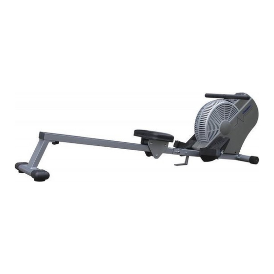
- Page 10 Onderdelen diagram...
- Page 11 Onderdelenlijst Onderdeel Nr. Beschrijving Aantal Hoofdframe Rails Achter standard Zitting houder Foam afstandshouder Stopper Voor standaard Eindkapje Schroef (M4 x 12mm) Linker kap Schroef (M5 x 15mm) Schroef (M5 x 25mm) Schroef (M5 x 70mm) Foam Rond eindkapje Stuur Busje Borgmoer (M8 x 1.25mm) Lager (698z) Trekkoord roller...
- Page 12 Inbusbout (M10 x 1.5 x 100mm) Stop bumper Bout (M8 x 1.25 x 15mm) Ovaal eindkapje (30mm x 60mm) Bout (M8 x 1.25 x 15mm) Afstansbusje Wieltje Asje Borgmoer (M10 x 1.5 x 7mm) Bout (M10 x 1.5 x 105mm) Bout (M6 x 1 x 15mm) Zitting Computer...
- Page 13 USER MANUAL Joy Sport Concept Air Power...
-
Page 14: Dear Customer
Dear customer, We want to thank you for having chosen a JOY SPORT product, and wish you a lot of fun and success during training with your JOY SPORT exercisers. Please note and follow the enclosed safety and assembly instructions carefully. -
Page 15: Before You Begin
BEFORE YOU BEGIN Thank you for choosing the Air Rower . We Although construct its products with take great pride in producing this quality product the finest materials and uses the highest standards and hope it will provide many hours of quality of manufacturing and quality control, there can exercise to make you feel better, look better, and sometimes be missing parts or incorrectly sized... -
Page 16: Hardware Identification Chart
HARDWARE IDENTIFICATION CHART This chart is provided to help identify the hardware used in the assembly process. Place the washers or the ends of the bolts or screws on the circles to check for the correct diameter. Use the small scale to check the length of the bolts and screws. - Page 17 ASSEMBLY INSTRUCTIONS Place all parts from the box in a cleared area and position them on the floor in front of you. Remove all packing materials from your area and place them back into the box. Do not dispose of the packing materials until assembly is completed.
- Page 18 ASSEMBLY INSTRUCTIONS STEP 3 Make sure the Wheels on the FRONT STABILIZER(7) face the front. Attach the FRONT STABILIZER(7) to the MAIN FRAME(1) with CARRIAGE BOLTS(M8x1.25x65mm)(71), ARC WASHERS(M8)(35), LOCK WASHERS(M8)(34), and ACORN NUTS(M8x1.25)(33). Wheel Wheel...
- Page 19 ASSEMBLY INSTRUCTIONS STEP 4 Locate the C Ring(48) on the STOPPER BAR(6). Insert the longer end of the STOPPER BAR(6) through the MAIN FRAME(1). Secure the STOPPER BAR(6) in position with the SPRING CLIP(46). STEP 5 There is an “L” decal on the LEFT PEDAL CAP(43L), and an “R” decal on the RIGHT PEDAL CAP(43R). Insert the PEDAL SHAFT(45) through the holes on the MAIN FRAME(1).
- Page 20 ASSEMBLY INSTRUCTIONS STEP 6 Slide the SEAT(66) onto the RAIL(2). Attach the STOPPER BUMPER(56) to the RAIL(2) with BUTTON HEAD BOLTS (22). Also, please verify that the other STOPPER BUMPER(56) have already (M8x1.25x25mm) been assembled at the factory. If it has not been pre-assembled, then please assemble at this time. STEP 7 Attach the REAR STAND(3) to the RAIL(2) with a HEX BOLT(M8x1.25x15mm)(59) and a LOCK WASHER(M8)(34) from inside the RAIL(2) and two FLAT HEAD BOLTS(M8x1.25x15mm)(57) from...
- Page 21 ASSEMBLY INSTRUCTIONS STEP 8 Attach the RAIL(2) to the MAIN FRAME(1) with BUTTON HEAD BOLT(M10x1.5x100mm)(55), WASHER(M10)(52), and ACORN NUT(M10x1.5)(51). Lock the RAIL(2) in position with the two LOCKING PINS(54). STEP 9 Install two AA batteries into the METER(67), the batteries are not included. See page 12 for detailed battery installation instructions.
-
Page 22: Operational Instructions
OPERATIONAL INSTRUCTIONS USING THE FITNESS METER POWER ON : Pull the HANDLEBAR(16) or push the button. DIST POWER OFF : Automatic shut off after four minutes of TIME inactivity. FUNCTION BUTTON: Press to select the function value displays of DISTANCE, TIME, and CALORIES. -
Page 24: Parts List
PARTS LIST PART# PART NAME Main Frame Rail Rear Stand Seat Carriage Foam Spacer Stopper Bar Front Stabilizer Front Endcap Screw, Round Head (M4 x 12mm) Left Cover Screw, Round Head (M5 x 15mm) Screw, Round Head (M5 x 25mm) Screw, Round Head (M5 x 70mm) Foam Grip Round Plug (25.4mm) - Page 25 PARTS LIST PART# PART NAME Stopper Bumper Bolt, Flat Head (M8 x 1.25 x 15mm) Oval Endcap (30mm x 60mm) Bolt, Hex Head (M8 x 1.25 x 15mm) Roller Spacer (ø10.2 x ø16 x 5.5mm) Roller Spacer Tube (ø10.2 x ø12 x 66mm) Nylock Nut (M10 x 1.5 x 7mm Thick) Bolt, Button Head (M10 x 1.5 x 105mm) Bolt, Round Head (M6 x 1 x 15mm)