
Related Manuals for Joy Sport CT-Economic


Summary of Contents for Joy Sport CT-Economic
- Page 1 J o y S p o r t The Choice Of The Experts Fitness-Import Timmermannsweg 46 5813 AP Ysselsteyn (LB) info@joysport.nl www.joysport.nl...
-
Page 2: Warning Decal Placement
INHOUDSOPGAVE Veiligheidsvoorschrift………………………………………………………………………………..1 Belangrijke veiligheids en Joy sport importeur …………………………………..…. 2-3 Hoofdbestanddelen.......……………………………………………………………………... 4-5 Hardware Kit.............…………………………………………......6 Montage instruktie........……………………………..………………………… . .7-12 Computerhandleid……………………………………………............13-20 Overzicht..……………………………………………................21 Onderdelenlijst..……………………………………………….……………………………………….22-23 Transport en opslag........…………….……………………………………...……….24 WARNING DECAL PLACEMENT... -
Page 3: Geachte Klant
Deze garantie geldt gedurende 24 maanden voor elke fabricagefout aan uw JOY SPORT product die door een JOY SPORT dealer werd verkocht. Wanneer u garantie claimt bied JOY SPORT de mogelijkheid om naar eigen goeddunken het defecte apparaat of het betreffende onderdeel te herstellen of te vervangen. - Page 4 Belangrijk, veiligheidsvoorschrift. Waarschuwing: Om risico of letsel van de gebruiker te voorkomen, lees deze instructie zorgvuldig. De eigenaar is er verantwoordelijk voor dat gebruikers kennis kunnen nemen van deze instructie. De trainer dient alleen gebruikt te worden als beschreven in de handleiding. Zorg dat de ventilatieopeningen vrij blijven van stof etc. Stop geen vreemde voorwerpen in de openingen. Plaats de trainer op een vlakke ondergrond, om vloer of tapijt te sparen kunt u er en mat onderleggen. Gebruik het apparaat niet buiten, want vocht en stof kunnen een nadelige invloed hebben op de werking en de levensduur van het apparaat De aanbevolen ruimte is 50 cm aan de zijkanten en 1 meter aan de achterkant om veilige werking mogelijk te maken en vrije ruimte om het apparaat te hebben. Maximaal gewicht gebruiker bedraagt 150 kg. Draag geschikte kleding tijdens gebruik en voorkom dat kledingstukken tussen de bewegende delen komen. De gegevens van de computer zijn geen precisie metingen maar enkel een indicatie voor de status van het moment en een hulpmiddel voor de trainingen. ...
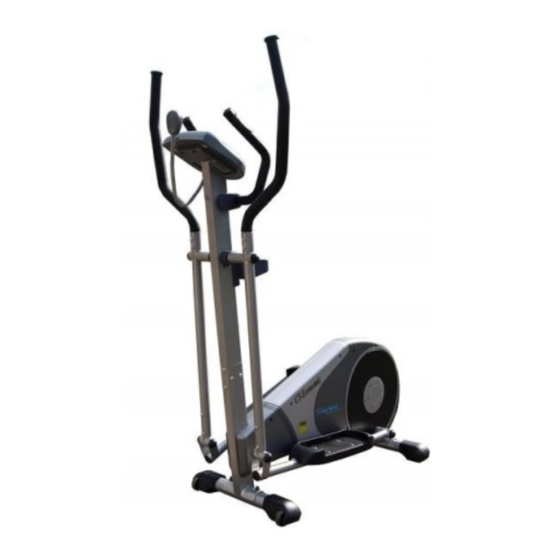
- Page 5 HARDWARE PACKAGE/PARTS/TOOLS CT-Economic Hoofd Frame Staander Console AC Adaptor Pedaal buis (L) Voetsteun(L) Pedaal buis(R) Voetsteun(R) Voorsteun Achterafdekking staander Achtersteun Handgreep( R )
- Page 6 HARDWARE PACKAGE/PARTS/TOOLS CT-Economic Bidonhouder Handgreep(L) Stuur Hardware Box (CT-Economic) Economic...
- Page 7 Montage onderdelen Joy Sport CT‐Economic Nummer Onderdeel Aantal Stap Nummer Onderdeel Aantal Stap Stap 1 Stap 6 Stap 1 Stap 6 Stap 1 Stap 7 Stap 1 Stap 7 Stap 2 Stap 8 Stap 2 Stap 8 Stap 2 Stap 8 Stap 2 Stap 9 Stap 3 Stap 10...
- Page 8 STAP:1 Voorsteun montage Nummer Nummer Aantal 1) Om de montage te vergemakkelijken, kunt u een blok verpakkingsmateriaal onder het hoofdframe plaatsen (zie foto). 2) Zet de voorsteun met transportwielen vast tegen het hoofdframe gebruik hiervoor de bouten (#19) vulringen (#65) en moeren (#20). 3) Zet de moeren goed vast en dek ze af met de kapjes (#21). STAP:2 Achtersteun montage Nummer Nummer Aantal 1) Om de montage te vergemakkelijken kunt u blok verpakkingsmateriaal onder het hoofdframe leggen (zie foto). 2) Zet achtersteun vast op het hoofdframe met 2 bouten (#19) vulringen (#65) moeren (#20). 3) Zet de moeren goed vast en dek ze af met kapjes (#21). STAP:3 Montage staander op hoofdframe Nummer Nummer Aantal 1) Houd de onderzijde van de staander tegen het frame en verbind de kabels. 2) Plaats staander op hoofdframe. 3) Monteer de 8 bouten (#18) eerst handvast en nadat alle bouten geplaatst zijn vastzetten. STAP:4 Voetsteun montage Nummer Nummer Aantal 1) Monteer beide pedalen (R#71/L#72) & voetsteunen (#52/#53) op de grond, controleer of links en rechts (R/L) bij elkaar (#71/#52) & (#72/#53) zitten. 2) Verbind de voetsteunen op de platen met de boutjes (#22) moeren (#20) en zet ze vast met de sleutel (zie tekening).
- Page 9 tool...
- Page 10 STAP:5 Montage pedaalarm Nummer Nummer Aantal 1) Selecteer linker en rechterpedaalarm deze zijn van labels voorzien. 2) Monteer de pedaalarmen aan het hoofdframe (#71H) zie tekening, 3) Monteer eerst de lange busje (#79) op de as (disc), dan de pedaalarmen (#71H), hierna de korte busje (#80) de vulringen (#17) en de zelfborgende moeren (#12) en zet deze vast. 4) Dek de moeren af met de kapjes (#5). STAP:6 Montage pedaalarm, met zwaaiarm Nummer Nummer Aantal 1) Monteer de verbindingsbuis (#83) aan de zwaaiarm (#66 & #67). 2) Monteer de boutjes (#18) zie tekening. 3) Monteer de eindkapjes (#5 ) en dek de moeren af. STAP:7 Montage boven zwaaiarm/handsteun Nummer Nummer Aantal 1) Monteer de bvenarm (#69 & #70) in de onderarm, let op links en rechts. 2) Draai de bovenarm voor de gaten, en zet deze vast met 2 bouten (#18). 3) Dek de bouten af met kapjes (#5). STAP:8 Montage stuur Nummer Nummer Aantal 1) Monteer het stuur (#68) met bouten (#6) en met de klemhouder tegen de staander. 2) Schuif beide sensorkabels door het kleine gaatje onder het stuur in de staander (#68). 3) Laat ze aan bovenzijde uit de staander steken. 4) Zet het stuurkapje vast met de schroeven ( #59).
- Page 12 STAP:9 Computer montage Nummer Nummer Aantal Verbind de kabels boven uit de staander met de kabels uit de computer. Zelfde kleuren bij elkaar houden, alleen de zwarte mogen onderling worden verwisseld. STAP:10 Bidonhouder montage Nummer Nummer Aantal 1) Monteer de steun (#89) op de bidonhouder (#90) samen met de 4 bouten (#92). 2) Monteer de houder op de staander met de schroeven (#30) en zet ze vast. (vast is vast) STAP:11 Adapter Nummer Nummer Aantal 1) Plaats adapter (#91) in geaard stopcontact. 2) Plaats de connector in het achtergedeelte van het apparaat.
- Page 14 Computer Handleiding Ⅰ. Inschakelen Stroom in: Sluit de stekker aan op een geaard stopcontact. Vervolgens de schakelaar naast de kabelingang op On zetten. Een luide piep klinkt, en het display licht op (Fig. 1) en gebruikersselectie verschijnt binnen enkele seconden. (Fig. 2) Uitschakelen: De console zal zichzelf uitschakelen na 4 minuten geen signaal te hebben ontvangen.
- Page 15 4. Instelling lengte In display licht “H.t” op rechts boven in Druk om uw lengte in te stellen Druk om uw lengte te bevestigen. ENTER 5. Instelling gewicht. Display geeft “W.t” aan rechts boven. Druk om uw gewicht in te stellen ...
- Page 16 6. PERSOONLIJKE PROGRAMMA INSTELLINGEN. Voor elk in te stellen programma,kunt u de waarden naar wens wijzigen. Als u drukt.. ENTER Kunt u LEVEL wijzigen Druk om instelling te wijzigen en druk om LEVEL te bevestigen ENTER Wijziging van tijd. Druk om te wijzigen en druk om TIME te bevestigen.
- Page 17 Druk bij H.R.C. (55%, 75%, 90%, Tag)… ENTER U kunt nu een hartslag programma selecteren, Druk om een programma te selecteren en druk om te bevestigen. ENTER Wijzigen tijd Druk naar gewenste waarde en druk om tijd te bevestigen. ENTER ...
- Page 18 Ⅲ. Vooringestelde Programma Diagrammen PROGRAM(P1-P12) ● P1 ● P2 ● P3 ● P4 ● P5 ● P6 ● P7 ● P8 ● P9 ● P10 ● P11 ● P12 HRC(55%, 75%, 90%, Tag) ●HRC(55%) ●HRC(75%) ●HRC(90%) ●HRC(Tag)
- Page 19 Fitness Evaluatie gegevens 1. Body Fat Instelling druk om te starten (Leg uw handen op de detectoren om uw hartslag te meten.) Als geen BODY FAT hartslag gemeten wordt binnen 10 minuten verschijnt error in het display. Als de hartslag gemeten wordt, body fat evaluatie begint en geeft aan na 25 sec.
- Page 20 2. Hartslag Evaluatie Deze geeft aan hoe uw hart functioneerd. Het geeft aan hoe uw hart hersteld na een inspannende training. NOTE! That the heart rate displayed may be inaccurate and used for reference om de test te beginnen (Plaats uw handen op de detectoren). Als de hartslag gemeten wordt Druk RECOVERY zal de meting beginnen en na 60 seconden uitslag geven.
- Page 21 6. BODY FAT Gebruik deze om programma te starten. 7. RECOVERY Gebruik deze knop voor hartslag evaluatie Specifikaties Item Display Display Range Setting Range Default Memory MALE/ FEM SEX(性别) 10 - 100 AGE(年龄) 20 - 330(Lb) WEIGHT(METRIC 公制)体重 10 - 150(KG) 36 - 84(INCH) HEIGHT(身高) 90 –...
- Page 24 Joy Sport CT-Economic Onderdelenlijst Nummer Omschrijving Nummer Omschrijving eindkap handgrteep verstelbare poot handgreep bout greepsteun vulring sensorhandgreep vliegwiel eindkap sensor kabel snelheid eindkap riem veerring eind kap vulring bout glijstng pedaal links glijstang pedaal rechts vulring vulring zerlfborgende moer eindkap...
- Page 25 Joy Sport CT-Economic Onderdelenlijst Nummer Omschrijving Nummer Omschrijving vulring vulring kabel 850MM zijafd links voedingskabel zijafd rechts achterafdekking staander handgreep bidon handgreep links AC ADAPTOR handgreep rechts bout vaste handgreep kabel 420MM schroevendraaier bout sleutel bout flesje olie vulring lager...
- Page 27 J o y S p o r t The Choice Of The Experts Fitness-Import Timmermannsweg 46 5813 AP Ysselsteyn (LB) info@joysport.nl www.joysport.nl...
- Page 28 TABLE OF CONTENTS WARNING DECAL PLACEMENT………………………………………………………………………………………. 1 IMPORTANT SAFTY/PRECAUTIONS INSTRUCTION…………………………………………………… …2-3 HARDWARE PACKAGE CONTENTS……………………………………………………………………………..4-5 PRE-ASSEMBLY INSTRUCTION & HARWARD KIT…………………………………………………..….6-7 ASSEMBLY INSTRUCTIONS……………………………..………………………………………………….. ……..8-14 CONSOLE MANUAL……………………………………………................15-22 EXERCISING/TRAINING………………………………………………………………………………………… …….23 MAINTENANCE AND TROUBLESHOOTING……………………………………………………………… ……24 EXPLODED VIEW…………………………………………………................25-26 PARTS LIST……………………………………………………….………………………………………………….. …27-28 TRANSPORT AND STORAGE/MALFUNCTIONS……………….……………………………………...….29-30 TECHICAL SPECIFICATIONS…………………………………………..............
-
Page 29: Dear Customer
Dear customer, We want to thank you for having chosen a JOY SPORT product, and wish you a lot of fun and success during training with your JOY SPORT exercisers. Please note and follow the enclosed safety and assembly instructions carefully. -
Page 30: Important Safety Instructions
IMPORTANT SAFETY INSTRUCTIONS IMPORTANT ELLIPTICAL EXERCISER WARNINGS AND CAUTIONS READ AND UNDERSTAND THESE WARNINGS AND CAUTIONS WARNING: In order to reduce the risk of injury to any and all persons, READ and UNDERSTAND the following important PRECATIONS and information before operating or allowing others to operate the elliptical exerciser. The owner has the responsibility of ensuring that all users of the elliptical exerciser are adequately informed of all warnings and precautions This elliptical exerciser should not be used by, on, or near children, invalids, or disabled persons. This elliptical exerciser must only be used as described in the manual. Attachments that are not recommended by the manufacturer must not be used. Never operate the elliptical exerciser with the air openings blocked, Keep the air openings free of lint, hair and the like. Never operate the elliptical exerciser on a soft surface such as a bed or a couch where the air openings may be blocked. Never drop or insert any object into any opening. Place the elliptical exerciser n a level surface. To protect the floor and carpet from damage, place a mat under the elliptical exerciser. DO NOT uses or store the elliptical exerciser outdoors, in a garage or covered patio, keep the elliptical exerciser away from moisture and dust. The elliptical exerciser should be used indoors. Heat, moisture and dirt can adversely affect the operation of this elliptical exerciser. ... - Page 31 HARDWARE PACKAGE/PARTS/TOOLS CT-Economic Base Frame Up right tube Console AC Adaptor Pedal tube(L) Pedal(L) Pedal tube(R) Pedal(R) Front stabilizer Rear cover for upright tube Rear stabilizer Handle bar ( R)
- Page 32 HARDWARE PACKAGE/PARTS/TOOLS CT-Economic Bottle holder Handle bar (L) Fix handle bar Hardware Box (CT-Economic) Economic...
- Page 33 Montage onderdelen Joy Sport CT‐Economic Nummer Onderdeel Aantal Stap Nummer Onderdeel Aantal Stap Stap 1 Stap 6 Stap 1 Stap 6 Stap 1 Stap 7 Stap 1 Stap 7 Stap 2 Stap 8 Stap 2 Stap 8 Stap 2 Stap 8 Stap 2 Stap 9 Stap 3 Stap 10...
- Page 34 STEP:1 FRONT SUPPORT ( Front Stabilizer) ASSY. part list QUANTITY As photo shown 1) in order to facilitate assembly, use one of the lager styroform set under the Frame ( as photo shown) 2) Attach the front support with transportation wheels to the frame with two bolts (#19) washers (#65) nuts (#20) 3) locking sleeves with tool and cover the nut with two caps (#21)。 STEP:2 REAR SUPPORT ( Rear Stabilizer) ASSY. part list QUANTITY As photo shown 1) In order to facilitate assembly, use one of the lager styroform set under the Frame ( as photo shown) 2) Attach the rear support to the frame with two bolts (#19) washers (#65) nuts (#20) 3) locking sleeves with tool and cover the nut with two caps (#21) STEP:3 UPRIGHT TUBE ASSY. TO THE FRAME part list QUANTITY As photo shown 1) place upright tube on top of a chair ( or by a second person to assist holding) close to the main frame be facilitated to connect the cables. 2) check the direction of upright tube before connect the Top/Bottom pre‐assembled cables as photo shown. 3) fixing eight screws (#18) with finger locking first then tighten all firmly. Note! tighten the two screws on the label "①" screw hold and then locking up the rest of six screws. STEP:4 PEDAL ASSY part list QUANTITY 1) Set both pedal tube (R#71/L#72) & plastic pedals(#52/#53) on the floor, indentity the (R/L) match up left set (#71/#52) & right set (#72/#53). Note! the pedal has left/right label, check the diredtion of pedl for front and foot protection edge of pedal as drawing shown) 2) lock up both pedals to the tube plate with screws(#22), nut (#20), with tool socket & screw driver firmly ( as drawing showm) Note! three sets of holds on the tube plate, user may choice one set to use,...
- Page 35 tool...
- Page 36 STEP:5 PEDAL SUPPORT TUBE ASSY(一) part list QUANTITY 1) Frist, distinguish between the left/right pedal support tube (note: check pedal 是upport tube with left/right label) 2) Set both pedal support tube (#71H) to the main frame as drawing shown first。 3) Insert long bushing (#79) to the axle on main frame (disc), then inset both pedal trube (#71H), insert short bushing (#80) washer (#1 7), secure each with M10 nylon lock nut (#12) fully tighten up 4) cover the nut with end cap (#5) STEP:6 PEDAL SUPPORT TUBE ASSY(二) part list QUANTITY 1) Insert both pre‐assembled connecting tube (#83) to each of swivel Tube (#66 & #67) 2) locking up both with screws (#18) as drawing shown。 3) Finally, set end cap (#5 )cover the nut. STEP:7 UPPER SWING ARM HANDLE BAR part list QUANTITY As photo shown 1) set the swing arm handle bar (#69 & #70) was insertd on the left L /Right R of the swing arm handlebar . 2) turn the handlebar on the aligned holes , secure both with two screws (#18) and lock. 3) Finally cover both nuts with end cap (#5) STEP:8 FIXED HANDLE BAR ASSY part list QUANTITY As photo shown 1) Fit the fixed handlebar (#68) with the screws (#6) and thru the bracket hold of upright tube with screw drive, 2) Set both EKG grip cables thru the small holes under the fie handlebar (#68) on the upright tube.
-
Page 38: Power Adaptor
STEP:9 CONSOLE ASSEMBLY part list QUANTITY 1) connect cables comes out from console (#43) & cables from the upright tube together. Note! check & plug cables, same color to be plug together. Black color can plug in with any black , no need to select special plug. Make sure all plug firmly in then insert all plugged cables to top of upright tube. 2) set console to the top plate on the upright tube and secure both with screws (E) STEP:10 DRINK HOLDER & STORAGE RACK ASSY part list QUANTITY As photo shown 1)First pre‐assy the dring holder base (#89) with bottle holder (#90) together with 4 screws (#92) 2) set the holder assy to the upright tube with screw (#30) firmly STEP:11 POWER ADAPTOR part list QUANTITY As photo shown 1) Plug the power cord with power adaptor (#91) into an appropriate outlet IMPORTANT: The elliptical exerciser is not compatible with GFCI‐equipped outlets. 2) The other end of the access hole in the rear of the base frame Note! before plug in, please check the voltage specifications on the label. - Page 40 Joy Sport CT-Advanced Ⅰ. Power Modes Power On: Plug in the power cord with power adaptor into an appropriate outlet. Next, locate and switch “on” the reset/off button on the frame, near the power cord . A loud beep will sound and the display will then light (Fig.
- Page 41 4. .HEIGHT SET UP The console will now flash “H.t” on the upper right-hand corner of the display. Press to select your height. Press to confirm HEIGHT. ENTER 5. .WEIGHT SET UP The console will now flash “W.t” on the upper right-hand corner of the display. ...
- Page 42 6. PERSONALIZE PROGRAM SETTINGS For each preset program, you can further personalize the level of work that you desire. If you pressed on MANUAL… ENTER You can now set up resistance LEVEL Press to adjust setting then press to confirm LEVEL set up. ENTER ...
- Page 43 If you pressed on H.R.C. (55%, 75%, 90%, Tag)… ENTER You can now select a preset target heart rate control program Press to select a program then press to confirm. ENTER You can now set up TIME Press to adjust target then press to confirm TIME set up.
- Page 44 Ⅲ. Preset Program Diagrams PROGRAM(P1-P12) ● P1 ● P2 ● P3 ● P4 ● P5 ● P6 ● P7 ● P8 ● P9 ● P10 ● P11 ● P12 HRC(55%, 75%, 90%, Tag) ●HRC(55%) ●HRC(75%) ●HRC(90%) ●HRC(Tag)
- Page 45 Fitness Evaluation Features 1. Body Fat Evaluation Press to begin evaluation (Put your for the machine to detect your hand on the EKG grips BODY FAT heart rate.) If no heart rate is detected after 10 minutes have lapsed, “ERROR” will appear on the display. If a heart rate is detected, body fat evaluation will begin and take about 25 seconds.
- Page 46 2. Recovery Heart Rate Evaluation A recovery heart rate is a measurement taken to help determine how well your heart is functioning. It refers to the heart's ability to return itself to a normal rhythm after being elevated during exercise. NOTE! That the heart rate displayed may be inaccurate and used for reference to begin the test.
- Page 47 5. ENTER Use this button to confirm your selection and go on to the next step. 6. BODY FAT Use button to start body fat evaluation test. 7. RECOVERY Use this button to start recovery heart rate evaluation test. Console Feature Specifications Item Display Display Range...
-
Page 50: Parts List
Joy Sport CT-Economic PARTS LIST Key Number Description Key Number Description Handlebar end cap Adjustable foot Handlebar grip Screw T-Bar grip Washer Hand pulse grip unit Flywheel End cap Speed Sensor Cable End cap Belt Locking washer End cap Washer... - Page 51 Joy Sport CT-Economic PARTS LIST Key Number Description Key Number Description Washer Washer Cable 850MM Side cover, LH Power wire 750MM Side cover, RH Rear cover for upright tube Handlebar grip Bottle holder Handle bar, LH (V200) AC ADAPTOR Handle bar, RH (V200)
Need help?
Do you have a question about the CT-Economic and is the answer not in the manual?
Questions and answers