Table of Contents
Advertisement
Quick Links
Advertisement
Table of Contents

Related Manuals for IEI Technology PICOe-6612 Series


Summary of Contents for IEI Technology PICOe-6612 Series
- Page 1 PICOe-6612...
- Page 2 PICOe-6612 REVISION HISTORY Title PICOe-6612 Intel Pentium M/Celeron M Motherbard Revision Number Description Date of Issue Initial release October 2006 COPYRIGHT NOTICE The information in this document is subject to change without prior notice in order to improve reliability, design and function and does not represent a commitment on the part of the manufacturer.
-
Page 3: Table Of Contents
PICOe-6612 Table of Contents INTRODUCTION....................15 1.1 PICO -6612 O ..................16 VERVIEW 1.1.1 PICOe-6612 Models ..................16 1.1.2 PICOe-6612 Benefits ..................16 1.1.3 PICOe-6612 Features ..................16 1.2 PICO -6612 O ..................17 VERVIEW 1.2.1 PICOe-6612 Connectors.................. 18 1.2.2 Technical Specifications................... 19 DETAILED SPECIFICATIONS ................ - Page 4 PICOe-6612 2.14 S .................... 32 YSTEM ONITORING 2.15 USB I ....................32 NTERFACES 2.16 BIOS ........................32 2.17 O ........32 PERATING EMPERATURE AND EMPERATURE ONTROL 2.18 A ......................33 UDIO ODEC 2.19 P ................... 34 OWER ONSUMPTION 2.20 P ........
- Page 5 PICOe-6612 3.3.3 USB Connector ....................65 3.3.4 VGA connector ....................66 INSTALLATION AND CONFIGURATION ............68 4.1 A ..................69 STATIC RECAUTIONS 4.2 I ................69 NSTALLATION ONSIDERATIONS 4.2.1 Installation Notices ..................69 4.3 U ......................70 NPACKING 4.3.1 Unpacking Precautions..................70 4.3.2 Checklist......................
- Page 6 PICOe-6612 5.1.1 Starting Setup....................94 5.1.2 Using Setup ...................... 94 5.1.3 Getting Help..................... 95 5.1.4 Unable to Reboot After Configuration Changes..........95 5.1.5 BIOS Menu Bar....................95 5.2 M ........................96 5.3 A ....................... 97 DVANCED 5.3.1 CPU Configuration..................98 5.3.2 IDE Configuration ..................
- Page 7 PICOe-6612 6.5 R LAN D E LAN) I ........159 EALTEK RIVER NSTALLATION 6.6 S S RAID D ................. 162 RIVER NSTALLATION 6.7 S S VGA U .................. 170 TILITIES RIVER BIOS CONFIGURATION OPTIONS ..............177 A.1 BIOS C ................178 ONFIGURATION PTIONS WATCHDOG TIMER ..................
- Page 8 PICOe-6612 List of Figures Figure 1-1: PICOe-6612 Overview................17 Figure 1-2: PICOe-6612 Solder Side Overview ............18 Figure 2-1: Data Flow Block Diagram................28 Figure 3-1: Connector and Jumper Locations ............38 Figure 3-2: Connector and Jumper Locations (Solder Side)........39 Figure 3-3: Audio Connector Location..............42 Figure 3-4: Backplane to Mainboard Connector Location ........43 Figure 3-5: CompactFlash Connector Location............44 Figure 3-6: DIO Connector Connector Locations ............46...
- Page 9 PICOe-6612 Figure 4-5: Connect the cooling fan cable ...............76 Figure 4-6: DIMM Module Installation................78 Figure 4-7: Clear CMOS Jumper ................80 Figure 4-8: LVDS Voltage Selection Jumper Pinout Locations......82 Figure 4-9: LVDS Voltage Selection Jumper Settings..........83 Figure 4-10: CompactFlash Card Installation............85 Figure 4-11: Dual RS-232 Cable Installation.............87 Figure 4-12: IDE Cable Connection ........
- Page 10 PICOe-6612 Figure 6-23: Install Shield..................164 Figure 6-24: License Agreement................165 Figure 6-25: Install Application Directory .............. 166 Figure 6-26: Select Needed Components .............. 167 Figure 6-27: Ready to Install ................... 168 Figure 6-28: Setup Status..................169 Figure 6-29: Restart the Computer ................. 170 Figure 6-30: Starting Install Shield Wizard ............
- Page 11 PICOe-6612 List of Tables Table 1-1: PICOe-6612 Model Specifications ............16 Table 1-2: Technical Specifications ................21 Table 2-1: Supported CPUs..................25 Table 2-2: Supported Pentium® M CPUs..............25 Table 2-3: Supported Celeron® M CPUs..............26 Table 2-4: Power Consumption .................34 Table 3-1: Peripheral Interface Connectors..............40 Table 3-2: Rear Panel Connectors................41 Table 3-3: Onboard Jumpers ..................41 Table 3-4: Audio Connector Pinouts .................42...
- Page 12 PICOe-6612 Table 3-24: VGA Connector Pinouts .................67 Table 4-1: Jumpers ....................79 Table 4-2: Clear CMOS Jumper Settings ..............80 Table 4-3: LVDS Voltage Selection Jumper Settings ..........81 Table 4-4: LVDS Voltage Selection Jumper Settings ..........83 Table 4-5: IEI Provided Cables...................84 Table 5-1: BIOS Navigation Keys................95 0-12...
- Page 13 PICOe-6612 List of BIOS Menus BIOS Menu 1: Main ....................96 BIOS Menu 2: Advanced.....................98 BIOS Menu 3: CPU Configuration................99 BIOS Menu 4: IDE Configuration ................101 BIOS Menu 5: IDE Master and IDE Slave Configuration........105 BIOS Menu 6: Floppy Configuration ..............109 BIOS Menu 7: Super IO Configuration ..............
- Page 14 PICOe-6612 Glossary AC ’97 Audio Codec 97 Hard Disk Drive ACPI Advanced Configuration and Integrated Data Electronics Power Interface Input/Output Advanced Power Management ICH4 I/O Controller Hub 4 ARMD ATAPI Removable Media Device L1 Cache Level 1 Cache ASKIR Shift Keyed Infrared L2 Cache Level 2 Cache Advanced Technology Liquid Crystal Display...
-
Page 15: Introduction
PICOe-6612 Chapter Introduction Page 15... -
Page 16: Picoe-6612 Overview
(PCIe) slots. The PICOe-6612 is designed for system manufacturers, integrators, and VARs that want performance, reliability, and quality at a reasonable price. 1.1.1 PICOe-6612 Models The PICOe-6612 series has four models: PICOe-6612-R10 PICOe-6612LVDS-R10 The specifications for the two models are show in Table 1-1. -
Page 17: Picoe-6612 Overview
PICOe-6612 RoHS compliant Socket 479 Intel® Pentium M/Celeron M processors supported Dual-independent display functionality Four PCI Master expansion boards supported Two PCI Express x1 (PCIe x 1) expansion boards supported Front side bus (FSB) up to 533MHz supported Up to 1GB of 400MHz DDR memory supported Dual channel 24-bit LVDS supported Two high performance gigabit Ethernet (GbE) controllers onboard Five USB 2.0 devices supported... -
Page 18: Picoe-6612 Connectors
PICOe-6612 Figure 1-2: PICOe-6612 Solder Side Overview 1.2.1 PICOe-6612 Connectors The PICOe-6612 has the following connectors onboard: 1 x Audio connector 1 x Backplane to mainboard connector 1 x CompactFlash connector 1 x Digital input/output (DIO) connector 1 x Fan connector 1 x Floppy disk drive connector 1 x Front panel connector 1 x IDE connector... -
Page 19: Technical Specifications
PICOe-6612 The PICOe-6612 has the following connectors on the board rear panel: 2 x Ethernet connectors 1 x PS/2 Keyboard/mouse connector 1 x USB connector 1 x VGA connector The PICOe-6612 has the following onboard jumpers: Clear CMOS LVDS voltage selection FSB voltage selection 1.2.2 Technical Specifications PICOe-6612 technical specifications are listed in Table 1-2. - Page 20 PICOe-6612 CompactFlash (CF) W83697HG Super I/O Audio Realtek ALC655 AC'97 Codec Dual RTL8110SC Two RS-232 serial connectors Five USB 2.0 devices supported by two onboard USB 2.0 USB2.0 connectors and one external USB 2.0 port One 40-pin IDE connects to two Ultra ATA33/66/100 devices One LPT port connector Parallel Port...
-
Page 21: Table 1-2: Technical Specifications
PICOe-6612 Dimensions 165mm x 115mm Weight (GW) Table 1-2: Technical Specifications Page 21... - Page 22 PICOe-6612 THIS PAGE IS INTENTIONALLY LEFT BLANK Page 22 IEI ® Technology, Corp.
-
Page 23: Detailed Specifications
PICOe-6612 Chapter Detailed Specifications Page 23... -
Page 24: Overview
PICOe-6612 2.1 Overview This chapter describes the specifications and onboard features of the PICOe-6612 in detail. 2.2 Compatible IEI Backplanes The PICOe-6612 CPU card is compatible with the following IEI PICMG 1.0 half-size HPE backplanes: HPE-3S1 HPE-3S2 HPE-4S1 HPE-4S2 HPE-5S1 HPE-5S2 HPE-5S3 HPE-6S1... -
Page 25: Pentium M
PICOe-6612 Mfg. Model Max. Speed L2 Cache Max. FSB Socket Intel ® Pentium® M 2.26GHz 533MHz Intel ® Celeron® M 1.73GHz 256KB 533MHz Table 2-1: Supported CPUs 2.4.1 Pentium M The Intel® Pentium® M CPU comes with the following features: Power Optimized 533/400 MHz processor system bus, Micro-ops Fusion &... -
Page 26: Onboard Chipsets
PICOe-6612 designs, including <1" thick Support for Intel® Mobile Voltage Positioning (Intel® MVP IV) dynamically lowers voltage based on processor activity to lower thermal design power, enabling smaller notebooks Lower core voltage – 1.356 V low-voltage operation and 24.5W thermal design power lower thermal dissipation enabling thinner notebooks Intel®... -
Page 27: Sis966 Southbridge Chipset
PICOe-6612 FSB 800MHz w/ 2X Address and 4X Data Rate 12 Outstanding Transactions support Quasi-Synchronous/Asynchronous Host/DRAM Timing support Supports 2M/4M/8M/16M TSEG SMRAM Supports Dynamic Bus Inversion. DRAM Controller DDR400/DDR333/DDR266 supported Up to two un-buffered DIMMs DDR400 supported Up to 1GB per DIMM with 512Mb tech. Dynamic Clock Enable (CKE) control placing the Memory into Suspend to DRAM state. -
Page 28: Data Flow
PICOe-6612 Supports 8 Channels High Definition Audio / AC'97 Advanced Power Management: ACPI 1.0b and APM 1.2 Compliant Dual IDE Channels with ATA 133/100 Support Up to 6 PCI Masters LPC 1.1 Interface Integrated Keyboard/PS2 Mouse Controller 2.6 Data Flow Figure 2-1 shows the data flow between the two onboard chipsets and other components installed on the motherboard and described in the following sections of this chapter. -
Page 29: Graphics Support
PICOe-6612 2.7 Graphics Support The graphics features listed below are all integrated on the SiS661CX northbridge chipset. AGP 3.5 and AGP 2.0 Compliant AGP 4X mode support Fast Write support 1.5V interface support only DX9 S/W Compliant High performance 256Bit 3D/128Bit 2D Graphic Engine 2 pixel rendering pipelines and 4 texture units per cycle (2P4T) Up to 200 MHz ECLK SiS Ultra-AGPII™... -
Page 30: Pci Bus Interface Support
PICOe-6612 2.9 PCI Bus Interface Support The PCI bus on the PICOe-6612 has the following features: 33MHz Revision 2.2 is implemented Maximum throughput: 133MB/sec One PCI REQ/GNT pair can be given higher arbitration priority (intended for external 1394 host controller) 2.10 GbE Ethernet The PICOe-6612 has two RTL8110SC GbE Ethernet controllers onboard. -
Page 31: Ide Hdd Interfaces
PICOe-6612 2.11.1 IDE HDD Interfaces The PICOe-6612 southbridge chipset IDE controller supports up to two HDDs with the following specifications: Supports PIO IDE transfers up to 16MB/s Supports the following Ultra ATA devices: Ultra ATA/100, with data transfer rates up to 100MB/s Ultra ATA/66, with data transfer rates up to 66MB/s Ultra ATA/33, with data transfer rates up to 33MB/s 2.11.2 Floppy Disk Drive (FDD) -
Page 32: Real Time Clock
PICOe-6612 2.13 Real Time Clock 256-byte battery backed CMOS RAM 2.14 System Monitoring The PICOe-6612 is capable of self-monitoring various aspects of its operating status including: CPU, chipset, and battery voltage, +3.3V, +5V, and +12V RPM of cooling fans CPU and board temperatures (by the corresponding embedded sensors) 2.15 USB Interfaces The PICOe-6612 supports five USB 2.0 or USB 1.1 devices. -
Page 33: Audio Codec
PICOe-6612 are also mounted on the northbridge and southbridge chipsets to ensure the operating temperature of these chips remain low. 2.18 Audio Codec The PICOe-6612 has an integrated REALTEK ALC655 CODEC. The ALC655 CODEC is a 16-bit, full-duplex AC'97 Rev. 2.3 compatible six-channel audio CODEC designed for PC multimedia systems, including host/soft audio and AMR/CNR-based designs. -
Page 34: Power Consumption
PICOe-6612 Standard 48-pin LQFP package EAX™ 1.0 & 2.0 compatible Direct Sound 3D™ compatible A3D™ compatible I3DL2 compatible HRTF 3D positional audio 10-band software equalizer Voice cancellation and key shifting in Karaoke mode AVRack® Media Player Configuration Panel for improved user convenience 2.19 Power Consumption Table 2-4 shows the power consumption parameters for the PICOe-6612 when a 2.13GHz Pentium M processor with a 2MB L2 cache and 533MHz FSB is running with a... -
Page 35: Optional Accessory Items
PICOe-6612 1 x Utility CD 1 x Quick Installation Guide 2.20.2 Optional Accessory Items The items shown in the list below are optional accessory items are purchased separately. USB cable 5.1 channel audio kit with Realtek ALC655 LPT cable FDD cable Page 35... - Page 36 PICOe-6612 THIS PAGE IS INTENTIONALLY LEFT BLANK Page 36 IEI ® Technology, Corp.
-
Page 37: Connectors And Jumpers
PICOe-6612 Chapter Connectors and Jumpers Page 37... -
Page 38: Peripheral Interface Connectors
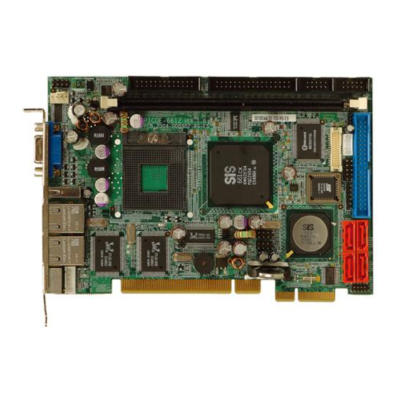
PICOe-6612 3.1 Peripheral Interface Connectors Section 3.1.1 shows peripheral interface connector locations. Section 3.1.2 lists all the peripheral interface connectors seen in Section 3.1.1. 3.1.1 PICOe-6612 Layout Figure 3-1 shows the onboard peripheral connectors, external peripheral interface connectors and onboard jumpers. Figure 3-1: Connector and Jumper Locations Page 38 IEI ®... -
Page 39: Peripheral Interface Connectors
PICOe-6612 Figure 3-2: Connector and Jumper Locations (Solder Side) 3.1.2 Peripheral Interface Connectors Table 3-1 shows a list of the peripheral interface connectors on the PICOe-6612. Detailed descriptions of these connectors can be found in Section 3.2 on page 41. Page 39... -
Page 40: Table 3-1: Peripheral Interface Connectors
PICOe-6612 Connector Type Label Audio connector 9-pin header J_AUDIO1 Backplane to mainboard connector 3-pin wafer ATXCTL1 CompactFlash (CF) connector 50-pin socket Digital Input/Output Connector 10-pin header DIO1 Fan connector 4-pin wafer CPU_FAN1 Floppy Disk connector 34-pin box header FDD1 Front Panel connector 8-pin header F_PANEL1 IDE Interface connector (Primary) -
Page 41: Rear Panel Connectors
PICOe-6612 3.1.3 Rear Panel Connectors Table 3-2 lists the rear panel connectors on the PICOe-6612. Detailed descriptions of these connectors can be found in Section 3.3 on page 63. Connector Type Label Ethernet connector RJ-45 LAN1 Ethernet connector RJ-45 LAN2 Keyboard/mouse connector Mini-DIN 6 PS/2 KB_MS1... -
Page 42: Audio Connector (9-Pin)
PICOe-6612 3.2.1 Audio Connector (9-pin) CN Label: J_AUDIO1 CN Type: 10-pin header (2x5) CN Location: See Figure 3-3 CN Pinouts: See Table 3-4 The audio connector is connected to an onboard codec. An external audio connector kit can be connected to the connector to provide sound input and output. Figure 3-3: Audio Connector Location PIN NO. -
Page 43: Backplane To Mainboard Connector
PICOe-6612 3.2.2 Backplane to Mainboard Connector CN Label: ATXCTL1 CN Type: 3-pin wafer (1x3) CN Location: See Figure 3-4 CN Pinouts: See Table 3-5 The Backplane to Mainboard connector closes the circuit between the mainboard and the backplane in which it is installed. The backplane should have an ATX connector and be powered by an ATX power supply. -
Page 44: Compactflash Connector
PICOe-6612 3.2.3 CompactFlash Connector CN Label: CF1 (solder side) CN Type: 50-pin socket (2x25) CN Location: See Figure 3-5 CN Pinouts: See Table 3-6 A CompactFlash memory module is inserted to the CompactFlash on the solder side of the PCB. Figure 3-5: CompactFlash Connector Location PIN NO. -
Page 45: Digital Input/Output (Dio) Connector
PICOe-6612 DATA 4 DATA 12 DATA 5 DATA 13 DATA 6 DATA 14 DATA 7 DATA 15 SDCS#1 SDCS#3 GROUND IOR# IOW# VCC_COM IRQ15 VCC_COM VCC_COM CSEL HDD_RESET IORDY SDREQ SDACK# HDD_ACTIVE# DATA 0 66DET DATA 1 DATA 8 DATA 2 DATA 9 DATA 10 VCC-IN CHECK2... -
Page 46: Fan Connector
PICOe-6612 The DIO connector is managed through a Super I/O chip. The DIO connector pins are user programmable. Figure 3-6: DIO Connector Connector Locations PIN NO. DESCRIPTION PIN NO. DESCRIPTION Output 3 Output 2 Output 1 Output 0 Input 3 Input 2 Input 1 Input 0... -
Page 47: Figure 3-7: Fan Connector Location
PICOe-6612 CN Pinouts: See Table 3-8 The cooling fan connector provides a 12V, 500mA current to a system cooling fan. The connector has a "rotation" pin to get rotation signals from fans and notify the system so the system BIOS can recognize the fan speed. Please note that only specified fans can issue the rotation signals. -
Page 48: Floppy Disk Connector
PICOe-6612 3.2.6 Floppy Disk Connector CN Label: FDD1 CN Type: 34-pin box header (2x17) CN Location: See Figure 3-8 CN Pinouts: See Table 3-9 The floppy disk connector (FDD1) is connected to a floppy disk drive. Figure 3-8: FDD Connector Location PIN NO. -
Page 49: Front Panel Connector
PICOe-6612 MOTOR ENABLE B# DIRECTION# STEP# WRITE DATA# WRITE GATE# TRACK 0# WRITE PROTECT# READ DATA# SIDE 1 SELECT# DISK CHANGE# Table 3-9: FDD Connector Pinouts 3.2.7 Front Panel Connector CN Label: F_PANEL1 CN Type: 12-pin header (2x6) CN Location: See Figure 3-9 CN Pinouts: See Table 3-10... -
Page 50: Ide Connector (Primary)
PICOe-6612 Figure 3-9: Front Panel Connector Locations FUNCTION DESCRIPTION FUNCTION DESCRIPTION Power PWRBTN- Power LED Button HDD LED Reset SYSRST- HDD LED- Table 3-10: Front Panel Connector Pinouts 3.2.8 IDE Connector (Primary) CN Label: PIDE1 CN Type: 40-pin box header (2x20) CN Location: See Figure 3-10 CN Pinouts:... -
Page 51: Figure 3-10: Primary Ide Device Connector Locations
PICOe-6612 Figure 3-10: Primary IDE Device Connector Locations PIN NO. DESCRIPTION PIN NO. DESCRIPTION RESET# GROUND DATA 7 DATA 8 DATA 6 DATA 9 DATA 5 DATA 10 DATA 4 DATA 11 DATA 3 DATA 12 DATA 2 DATA 13 DATA 1 DATA 14 DATA 0... -
Page 52: Ir Interface Connector (6-Pin)
PICOe-6612 INTERRUPT P66DET HDC CS0# HDC CS1# HDD ACTIVE# GROUND Table 3-11: Primary IDE Connector Pinouts 3.2.9 IR Interface Connector (6-pin) CN Label: CN Type: 6-pin header (1x6) CN Location: See Figure 3-11 CN Pinouts: See Table 3-12 The integrated infrared (IrDA) connector supports both Serial Infrared (SIR) and Amplitude Shift Key Infrared (ASKIR) interfaces. -
Page 53: Figure 3-11: Ir Connector Pinout Locations
PICOe-6612 Figure 3-11: IR Connector Pinout Locations PIN NO. DESCRIPTION IRRX IRTX CIRRX Table 3-12: IR Connector Pinouts Page 53... -
Page 54: Keyboard Connector
PICOe-6612 3.2.10 Keyboard Connector CN Label: CN Type: 5-pin wafer (1x5) CN Location: See Figure 3-12 CN Pinouts: See Table 3-13 The keyboard connector can be connected to a standard keyboard directly. Figure 3-12: Keyboard Connector Location PIN NO. DESCRIPTION KEYBOARD CLOCK KEYBOARD DATA GROUND... -
Page 55: Lcd Lvds Connector
PICOe-6612 3.2.11 LCD LVDS Connector CN Label: LVDS1 CN Type: 30-pin crimp (2x15) CN Location: See Figure 3-13 CN Pinouts: See Figure 3-13 The LVDS LCD connector (LVDS1) connects to a one or dual channel 24-bit LVDS panel. Page 55... -
Page 56: Figure 3-13: Lvds Connector Locations
PICOe-6612 Figure 3-13: LVDS Connector Locations DESCRIPTION DESCRIPTION LVDSA_Y0+ LVDSA_Y0- LVDSA_Y1+ LVDSA_Y1- LVDSA_Y2+ LVDSA_Y2- LVDSA_CLK+ LVDSA_CLK- LVDSA_Y3+ LVDSA_Y3- LVDSB_Y0+ LVDSB_Y0- LVDSB_Y1+ LVDSB_Y1- LVDSB_Y2+ LVDSB_Y2- LVDSB_CLK+ LVDSB_CLK- LVDSB_Y3+ LVDSB_Y3- LVDS_VCC LVDS_VCC LVDS_VCC LVDS_VCC Table 3-14: LCD LVDS Connector Pinouts Page 56 IEI ®... -
Page 57: Panel Backlight Connector
PICOe-6612 3.2.12 Panel Backlight Connector CN Label: INVERTER1 CN Type: 5-pin wafer (1x5) CN Location: See Figure 3-14 CN Pinouts: See Table 3-15 The Panel Backlight connector provides the backlight on the LCD panel connected to the PICOe-6612 with +12V of power Figure 3-14: Panel Backlight Connector Pinout Locations PIN NO. -
Page 58: Parallel Port Connector
PICOe-6612 GROUND BACKLIGHT ENABLE Table 3-15: Panel Backlight Connector Pinouts 3.2.13 Parallel Port Connector CN Label: LPT1 CN Type: 26-pin box header CN Location: See Figure 3-15 CN Pinouts: See Table 3-16 The PICOe-6612 has one 26-pin header that can be connected to a parallel port connector interface or some other parallel port device such as a printer. -
Page 59: Serial Port Connectors
PICOe-6612 DATA 3 DATA 4 DATA 5 DATA 6 DATA 7 ACKNOWLEDGE BUSY PAPER EMPTY PRINTER SELECT AUTO FORM FEED # ERROR# INITIALIZE PRINTER SELECT LN# GROUND GROUND GROUND GROUND GROUND GROUND GROUND GROUND Table 3-16: Parallel Port Connector Pinouts 3.2.14 RS-232 Serial Port Connectors CN Label: COM1 and COM2... -
Page 61: Sata Drive Connectors
PICOe-6612 3.2.15 SATA Drive Connectors CN Label: SATA1, SATA2, SATA3 and SATA4 CN Type: 7-pin SATA drive connectors CN Location: See Figure 3-17 CN Pinouts: See Table 3-18 The two SATA drive connectors are connected to two first generation SATA drives. First generation SATA drives transfer data at speeds as high as 150Mb/s. -
Page 62: Internal Usb Connectors
PICOe-6612 Table 3-18: SATA Drive Connector Pinouts 3.2.16 Internal USB Connectors CN Label: USB01 and USB23 CN Type: 8-pin header (2x4) CN Location: See Figure 3-18 CN Pinouts: See Table 3-19 The two 2x4 USB pin connectors provide connectivity to four additional USB 2.0 ports. The USB connectors can support two USB devices each. -
Page 64: Lan Connectors
PICOe-6612 Figure 3-20: PS/2 Pinouts DESCRIPTION KEYBOARD DATA MOUSE DATA KEYBOARD CLOCK MOUSE CLOCK Table 3-20: Mini-DIN 6 PS/2 Connector Pinouts 3.3.2 LAN Connectors CN Label: LAN1 and LAN2 CN Type: RJ-45 CN Location: See Figure 3-19 CN Pinouts: See Table 3-21 The PICOe-6612 is equipped with two built-in GbE Ethernet controllers. -
Page 65: Usb Connector
PICOe-6612 DESCRIPTION DESCRIPTION TXA+ TXC- TXA- TXB- TXB+ TXD+ TXC+ TXD- Table 3-21: LAN Pinouts Figure 3-21: RJ-45 Ethernet Connector The RJ-45 Ethernet connector has two status LEDs, one green and one yellow. The green LED indicates activity on the port and the yellow LED indicates the port is linked. See Table 3-22. -
Page 67: Table 3-24: Vga Connector Pinouts
PICOe-6612 GROUND DDCCLK GROUND Table 3-24: VGA Connector Pinouts Page 67... -
Page 68: Installation And Configuration
PICOe-6612 Chapter Installation and Configuration Page 68 IEI ® Technology, Corp. -
Page 69: Anti-Static Precautions
PICOe-6612 4.1 Anti-static Precautions Electrostatic discharge (ESD) can cause serious damage to electronic components, including the PICOe-6612. (Dry climates are especially susceptible to ESD.) It is therefore critical that whenever the PICOe-6612 (or any other electrical component) is handled, the following anti-static precautions are strictly adhered to. -
Page 70: Unpacking
PICOe-6612 When installing or configuring the motherboard, place it on an antistatic pad. This helps to prevent potential ESD damage. Turn off all power to the PICOe-6612: When working with the motherboard, make sure that it is disconnected from all power supplies and that no electricity is being fed into the system. Before and during the installation of the PICOe-6612 DO NOT: remove any of the stickers on the PCB board. -
Page 71: Checklist
4.4 PICOe-6612 Motherboard Installation WARNING! Never run the motherboard without an appropriate heatsink and cooler that can be ordered from IEI Technology or purchased separately. WARNING! Please note that the installation instructions described in this manual should be carefully followed in order to avoid damage to the motherboard components and injury to the user. - Page 72 PICOe-6612 WARNING! When installing electronic components onto the motherboard always take the anti-static precautions listed above in order to prevent ESD damage to the motherboard and other electronic components like the CPU and DIMM modules The following components must be installed onto the motherboard or connected to the motherboard during the installation process.
-
Page 73: Cpu Installation
PICOe-6612 4.4.1 CPU Installation WARNING! CPUs are expensive and sensitive components. When installing the CPU please be careful not to damage it in anyway. Make sure the CPU is installed properly and ensure that a heatsink and CPU cooling fan is properly installed before the motherboard is run or else both the CPU and the board may be damaged. -
Page 74: Figure 4-2: Lock The Cpu Socket Retention Screw
PICOe-6612 Step 3: Correctly position the CPU. Make sure the pin 1 mark matches the cut edge on the CPU socket. Carefully place the CPU on top of the socket. When properly placed, the CPU should be easily inserted into the socket. Step 4: Insert the CPU. -
Page 75: Cooling Kit (Cf-479B-Rs ) Installation
PICOe-6612 4.4.2 Cooling Kit (CF-479B-RS ) Installation Figure 4-3: IEI CF-479B-RS Cooling Kit IEI provides a cooling kit designed for socket 479 CPUs. (See Figure 4-3) The cooling kit is comprised of a CPU heat sink and a cooling fan. NOTE: The CF-479B-RS heat sink comes with a sprayed layer of thermal paste. -
Page 76: Figure 4-4: Cooling Kit Support Bracket
PICOe-6612 Figure 4-4: Cooling Kit Support Bracket Step 4: Tighten the screws. Use a screwdriver to tighten the four screws. Tighten each nut a few turns at a time and do not over-tighten the screws. Step 5: Connect the fan cable. Connect the cooling kit fan cable to the fan connector on the motherboard. -
Page 77: Dimm Module Installation
PICOe-6612 4.4.3 DIMM Module Installation 4.4.3.1 Purchasing the Memory Module When purchasing DIMM modules, the following considerations should be taken into account: The DIMM module can support a memory chip with a maximum size of 1GB The DIMM module supports SDRAM DIMM speeds of 200MHz and 266MHz 4.4.3.2 DIMM Module Installation The PICOe-6612 motherboard has one DDR SDRAM DIMM socket. -
Page 78: Jumper Settings
PICOe-6612 Figure 4-6: DIMM Module Installation 4.5 Jumper Settings NOTE: A jumper is a metal bridge that is used to close an electrical circuit. It consists of two metal pins and a small metal clip (often protected by a plastic cover) that slides over the pins to connect them. -
Page 79: Clear Cmos Jumper
PICOe-6612 Before the PICOe-6612 is installed in the system, the jumpers must be set in accordance with the desired configuration. The PICOe-6612 motherboard has three on-board jumpers. Description Label Type Clear CMOS J_CMOS1 3-pin header LVDS Voltage Selection J_LVDS1 3-pin header FSB reference voltage J_VCCA1 2-pin header... -
Page 80: Figure 4-7: Clear Cmos Jumper
PICOe-6612 Clear CMOS DESCRIPTION Short 1 - 2 (Default) Keep CMOS Setup Short 2 - 3 Clear CMOS Setup Table 4-2: Clear CMOS Jumper Settings The location of the clear CMOS jumper is shown in Figure 4-7 below. Figure 4-7: Clear CMOS Jumper Page 80 IEI ®... -
Page 81: Lvds Voltage Selection
PICOe-6612 4.5.2 LVDS Voltage Selection WARNING Permanent damage to the screen and PICOe-6612 may occur if the wrong voltage is selected with this jumper. Please refer to the user guide that cam with the monitor to select the correct voltage. Jumper Label: J_LVDS1 Jumper Type:... -
Page 82: Lvds Voltage Selection
PICOe-6612 Figure 4-8: LVDS Voltage Selection Jumper Pinout Locations 4.5.3 LVDS Voltage Selection Jumper Label: J_LVDS1 Jumper Type: 2-pin header Jumper Settings: See Figure 4-9 Jumper Location: See Table 4-4 The VCCA Voltage (FSB reference voltage) can be selected by using J_VCCA1. Use the jumper to short or open J_VCCA1 to achieve the function of VCCA Voltage selection. -
Page 83: Chassis Installation
PICOe-6612 Dothan(FSB100)-->VCCA 1.8V Dothan(FSB133)-->VCCA 1 J_VCCA1 DESCRIPTION +1.8V VCCA +1.5V VCCA Table 4-4: LVDS Voltage Selection Jumper Settings The LVDS Voltage Selection jumper location is shown in Figure 4-9. Figure 4-9: LVDS Voltage Selection Jumper Settings 4.6 Chassis Installation Cables provided by IEI that connect peripheral devices to the PICOe-6612 are listed in Table 4-5. -
Page 84: Chassis Selection
PICOe-6612 Quantity Type ATA 66/100 flat cable Dual RS-232 cable SATA drive cable SATA drive power cable KB/MS Y cable Table 4-5: IEI Provided Cables To install the PICOe-6612 into a chassis, please follow the steps below. Step 1: Select a chassis Step 2: Install a backplane into a chassis Step 3:... -
Page 85: Install The Compactflash Card
PICOe-6612 The PICOe-6612 must be installed onto a PCI backplane. PCI backplanes are available from IEI. Please visit the IEI website (www.ieiworld.com) or contact an IEI sales representative for more details. To install the backplane into the chassis, please refer to the chassis and backplane user guides respectively. -
Page 86: Mount The Picoe-6612 Onto The Backplane
PICOe-6612 4.6.4 Mount the PICOe-6612 onto the Backplane To install the PICOe-6612, please follow the steps below: Step 1: Align the gold-finger connectors on the bottom of the PICOe-6612 with the respective PCI slot on the backplane. For details refer to the documentation that came with the backplane. -
Page 87: Usb 2.0 Cable Connection
PICOe-6612 Figure 4-11: Dual RS-232 Cable Installation Step 3: Secure the bracket supporting the two D-sub 9 male connectors to the chassis. To do this, please refer to the chassis manual. Step 0: 4.6.6 USB 2.0 Cable Connection The PICOe-6612 is shipped with a dual USB cable. The dual USB cable consists of two connectors attached to two independent cables. -
Page 88: Ide Disk Drive Connector (Ide1)
PICOe-6612 4.6.7 IDE Disk Drive Connector (IDE1) The PICOe-6612 is shipped with an ATA 66/100 flat cable. The cable is connected to the PICO-822 and to one or two IDE HDD. To connect an IDE HDD to the PICOe-6612, follow the instructions below. -
Page 89: Sata Drive Connection
PICOe-6612 Step 5: Connect the other side of the cable to the HDD making sure that the pin 1 cable corresponds to pin 1 on the connectorStep 0: 4.6.8 SATA Drive Connection The PICOe-6612 four onboard 150Mb/s SATA drive connectors. The PICOe-6612 is shipped with two SATA drive cables and one SATA drive power cable. -
Page 90: Rear Panel Connectors
PICOe-6612 Step 4: Connect the SATA power connector to the back of the SATA drive (Figure 4-14). Figure 4-14: SATA Drive Connection 4.7 Rear Panel Connectors 4.7.1 LCD Panel Connection Connect the VGA connector to a standard monitor. 4.7.2 Ethernet Connection The rear panel RJ-45 connectors can be connected to an external LAN and communicate with data transfer rates up to 1Gb/s. -
Page 91: Usb Connection
PICOe-6612 4.7.3 USB Connection The rear panel USB connector provides easier and quicker access to external USB devices. The rear panel USB connector is a standard connector and can easily be connected to other USB devices. 4.7.4 Keyboard and Mouse Connection A PS/2 keyboard and a PS/2 mouse can be connected to the appropriate PS/2 connector on the rear panel. - Page 92 PICOe-6612 THIS PAGE IS INTENTIONALLY LEFT BLANK Page 92 IEI ® Technology, Corp.
-
Page 93: Ami Bios Setup
PICOe-6612 Chapter AMI BIOS Setup Page 93... -
Page 94: Introduction
PICOe-6612 5.1 Introduction A licensed copy of AMI BIOS is preprogrammed into the ROM BIOS. The BIOS setup program allows users to modify the basic system configuration. This chapter describes how to access the BIOS setup program and the configuration options that may be changed. -
Page 95: Getting Help
PICOe-6612 F2 /F3 key Change color from total 16 colors. F2 to select color forward. F10 key Save all the CMOS changes, only for Main Menu Table 5-1: BIOS Navigation Keys 5.1.3 Getting Help When F1 is pressed a small help window describing the appropriate keys to use and the possible selections for the highlighted item appears. -
Page 96: Main
PICOe-6612 5.2 Main When the BIOS Setup program is entered, the Main menu (BIOS Menu 1) appears. The Main menu gives an overview of the basic system information. BIOS Menu 1: Main System Overview The System Overview lists a brief summary of different system components. The fields in System Overview cannot be changed. -
Page 97: Advanced
PICOe-6612 Type: Names the currently installed processor Speed: Lists the processor speed Count: The number of CPUs on the motherboard System Memory: Displays the auto-detected system memory. Size: Lists memory size The System Overview field also has two user configurable fields: System Time [xx:xx:xx]: The system time is set here. -
Page 98: Cpu Configuration
PICOe-6612 BIOS Menu 2: Advanced 5.3.1 CPU Configuration The CPU Configuration menu (BIOS Menu 3) shows detailed CPU specifications and CPU configuration options. Page 98 IEI ® Technology, Corp. - Page 99 PICOe-6612 BIOS Menu 3: CPU Configuration The CPU Configuration menu (BIOS Menu 3) lists the following CPU details: Manufacturer: Lists the name of the CPU manufacturer Brand String: Lists the brand name of the CPU being used Frequency: Lists the CPU processing speed FSB Speed: Lists the FSB speed Cache L1: Lists the CPU L1 cache size Cache L2: Lists the CPU L2 cache size...
-
Page 100: Ide Configuration
PICOe-6612 Disabled Code can be executed in any memory area. Enabled Code execution in data-only memory pages is EFAULT prohibited. CPU TM Function [Enabled] Use the CPU TM Function option to enable or disable the CPU TM function. Disabled CPU TM Function disabled Enabled CPU TM Function enabled EFAULT... - Page 101 PICOe-6612 BIOS Menu 4: IDE Configuration OnBoard PCI IDE Controller [Both] Use the OnBoard PCI IDE Controller BIOS option to specify the IDE channels used by the onboard PCI IDE controller. The following configuration options are available. Prevents the system from using the onboard IDE Disabled controller Primary...
- Page 102 PICOe-6612 channel, including both the Secondary Master and Secondary Slave Both Allows the system to detect both the Primary and EFAULT Secondary IDE channels including the Primary Master, Primary Slave, Secondary Master and Secondary Slave. SATA Mode Selection [4P(IDE) + 4S(RAID)] Use the SATA Mode Selection option to specify the maximum number of drives that can be used on the system.
- Page 103 PICOe-6612 Hard Disk Write Protect [Disabled] Use the Hard Disk Write Protect BIOS option to protect the hard disks from being overwritten. This menu item is only effective if the device is accessed through the BIOS. Disabled Allows hard disks to be overwritten EFAULT Enabled Prevents hard disks from being overwritten...
-
Page 104: Ide Master, Ide Slave
PICOe-6612 Host & Device Both the motherboard onboard IDE controller and EFAULT IDE disk drive are used to detect the type of IDE cable used. Host The motherboard onboard IDE controller detects the type of IDE cable used. The IDE disk drive to detects the type of IDE cable Device used. - Page 105 PICOe-6612 BIOS Menu 5: IDE Master and IDE Slave Configuration Auto-Detected Drive Parameters The “grayed-out” items in the left frame are IDE disk drive parameters automatically detected from the firmware of the selected IDE disk drive. The drive parameters are listed as follows: Device: Lists the device type (e.g.
- Page 106 PICOe-6612 S.M.A.R.T.: Indicates whether or not the Self-Monitoring Analysis and Reporting Technology protocol is supported. 32Bit Data Transfer: Enables 32-bit data transfer. Type [Auto] Use the Type BIOS option select the type of device the AMIBIOS attempts to boot from after the Power-On Self-Test (POST) is complete.
- Page 107 PICOe-6612 the specified channel. Auto BIOS auto detects the LBA mode control on the specified EFAULT channel. Block (Multi Sector Transfer) [Auto] Use the Block (Multi Sector Transfer) to disable or enable BIOS to auto detect if the device supports multi-sector transfers. Disabled BIOS is prevented from using Multi-Sector Transfer on the specified channel.
-
Page 108: Floppy Configuration
PICOe-6612 (This setting generally works with all hard disk drives manufactured after 1999. For other disk drives, such as IDE CD-ROM drives, check the specifications of the drive.) DMA Mode [Auto] Use the DMA Mode BIOS selection to adjust the DMA mode options. Auto BIOS auto detects the DMA mode. - Page 109 PICOe-6612 BIOS Menu 6: Floppy Configuration Floppy A [Disabled] The Floppy A configuration option determines the types of the floppy drive installed in the system. The following configuration options are available. Disabled (default) 360 KB 5¼” 1.2 MB 5¼” 720 KB 3 ½” 1.44 MB 3½”...
-
Page 110: Super Io Configuration
PICOe-6612 The Floppy B configuration option determines the types of the floppy drive installed in the system. The following configuration options are available. Disabled (default) 360 KB 5¼” 1.2 MB 5¼” 720 KB 3 ½” 1.44 MB 3½” 2.88 MB 3½” 5.3.4 Super IO Configuration The Super IO Configuration menu (BIOS Menu 7) sets or changes the configurations for the FDD controllers, parallel ports and serial ports. - Page 111 PICOe-6612 On Board Floppy Controller [Enabled] Use the Onboard Floppy Controller to enable or disable the floppy driver controller. Disabled BIOS disables the floppy controller Enabled (Default) BIOS enables the floppy controller Serial Port1 Address [3F8/IRQ4] Use the Serial Port1 Address option to select the Serial Port 1 base address. No base address is assigned to Serial Port 1 Disabled 3F8/IRQ4...
- Page 112 PICOe-6612 Serial Port2 Mode [Normal] Use the Serial Port2 Mode option to select the Serial Port2 operational mode. Normal Serial Port 2 mode is normal EFAULT IrDA Serial Port 2 mode is IrDA ASK IR Serial Port 2 mode is ASK IR Parallel Port Address [Disabled] Use the Parallel Port Address option to select the parallel port base address.
-
Page 113: Hardware Health Configuration
PICOe-6612 Normal mode. ECP+EPP The parallel port operates in the extended capabilities port (ECP) mode. The ECP mode supports bi-directional communication between the system and the parallel port device and the transmission rates between the two are much faster than the Normal mode The parallel port is also be compatible with EPP devices described above Parallel Port IRQ [IRQ7]... - Page 114 PICOe-6612 BIOS Menu 8: Hardware Health Configuration The following system parameters and values are shown. The system parameters that are monitored are: System Temperatures: The following system temperatures are monitored Temperature Sensor #1 System Temperature Fan Speeds: The CPU cooling fan speed is monitored. Fan2 Speed Voltages: The following system voltages are monitored Vcore...
-
Page 115: Acpi Configuration
PICOe-6612 –5Vin 5.3.6 ACPI Configuration The ACPI Configuration menu (BIOS Menu 9) configures the Advanced Configuration and Power Interface (ACPI) and Power Management (APM) options. BIOS Menu 9: ACPI Configuration ACPI Aware O/S [Yes] Use the ACPI Aware O/S option to enable the system to configure ACPI power saving options. -
Page 116: Advanced Acpi Configuration
PICOe-6612 Enables the ACPI support for the operating system. This EFAULT selection should be enabled if the OS does support ACPI 5.3.6.1 Advanced ACPI Configuration Use the Advanced ACPI Configuration menu (BIOS Menu 10) to select the ACPI state when the system is suspended. BIOS Menu 10: General ACPI Configuration Page 116 IEI ®... -
Page 117: Mps Configuration
PICOe-6612 ACPI 2.0 Features Use the ACPI 2.0 Features option to enable the ACPI (Advanced Configuration and Power Interface) features. By enabling this feature the system RSDP (Root System Description Pointer) is able to obtain physical addresses for other 64-bit fixed system description tables. - Page 118 PICOe-6612 BIOS Menu 11: MPS Configuration MPS Revision [1.4 The Multiprocessor Specification (MPS) for OS specifies the MPS version to be used. MPS version 1.1 is used MPS version 1.4 is used EFAULT Page 118 IEI ® Technology, Corp.
-
Page 119: Usb Configuration
PICOe-6612 5.3.8 USB Configuration The USB Configuration menu (BIOS Menu 12) gives USB configuration information and configures some USB features. BIOS Menu 12: USB Configuration Onboard SiS USB1.1 DEVICE [Enabled] Use the Onboard SiS USB1.1 DEVICE BIOS option to enable or disable the onboard SiS USB1.1 controller. - Page 120 PICOe-6612 Use the Onboard SiS USB2.0 DEVICE option to enable or disable the onboard SiS USB2.0 controller. If disabled, USB2.0 devices cannot be used. Disabled USB 2.0 interface is disabled and cannot be used. Enabled USB 2.0 interface is enabled and can be used. EFAULT Legacy USB Support [Enabled] Use the Legacy USB Support BIOS option to enable USB mouse and USB keyboard...
-
Page 121: Pci/Pnp
PICOe-6612 use the EHCI handoff functionality. Enabled Systems with OSes that do not support EHCI cannot EFAULT use the EHCI handoff functionality. 5.4 PCI/PnP The PCI/PnP menu (BIOS Menu 12) configures advanced PCI and PnP settings. WARNING! Setting wrong values for the BIOS selections in the PCIPnP BIOS menu may cause the system to malfunction. - Page 122 PICOe-6612 BIOS Menu 13: PCI/PnP Configuration Page 122 IEI ® Technology, Corp.
- Page 123 PICOe-6612 Clear NVRAM [No] Use the Clear NVRAM option to specify if the NVRAM (Non-Volatile RAM) is cleared when the power is turned off. System does not clear NVRAM during system boot EFAULT System clears NVRAM during system boot Plug & Play O/S [No] Use the Plug &...
- Page 124 PICOe-6612 Allocate IRQ to PCI VGA [Yes] Use the Allocate IRQ to PCI VGA option to restrict the system from giving the VGA adapter card an interrupt address. Assigns an IRQ to a PCI VGA card if card requests IRQ EFAULT Does not assign IRQ to a PCI VGA card even if the card requests an IRQ...
- Page 125 PICOe-6612 OffBoard PCI/ISA IDE Card [Auto] Use the Off Board PCI/ISA IDE Card BIOS option to select the OffBoard PCI/ISA IDE Card. The location of the Off Board PCI IDE adapter card is Auto EFAULT automatically detected by the AMIBIOS. PCI Slot 1 PCI Slot 1 is selected as the location of the OffBoard PCI IDE adapter card.
- Page 126 PICOe-6612 Available The specified IRQ is available to be used by EFAULT PCI/PnP devices The specified IRQ is reserved for use by Legacy ISA Reserved devices Available IRQ addresses are: IRQ3 IRQ4 IRQ5 IRQ7 IRQ9 IRQ10 IRQ 11 IRQ 14 IRQ 15 DMA Channel# [Available] Use the DMA Channel# option to assign a specific DMA channel to a particular PCI/PnP...
-
Page 127: Boot
PICOe-6612 Reserved Memory Size [Disabled] Use the Reserved Memory Size BIOS option to specify the amount of memory that should be reserved for legacy ISA devices. Disabled No memory block reserved for legacy ISA devices EFAULT 16KB reserved for legacy ISA devices 32KB reserved for legacy ISA devices 54KB reserved for legacy ISA devices 5.5 Boot... -
Page 128: Boot Settings Configuration
PICOe-6612 5.5.1 Boot Settings Configuration The Boot Settings Configuration menu (BIOS Menu 14) configures advanced system boot options. BIOS Menu 15: Boot Settings Configuration Quick Boot [Enabled] Use the Quick Boot BIOS option to make the computer speed up the boot process. Disabled No POST procedures are skipped Enabled... - Page 129 PICOe-6612 Quiet Boot [Disabled] Use the Quiet Boot BIOS option to select the screen display when the system boots. Disabled Normal POST messages displayed EFAULT Enabled OEM Logo displayed instead of POST messages AddOn ROM Display Mode [Force BIOS] Use the AddOn ROM Display Mode option to allow add-on ROM (read-only memory) messages to be displayed.
- Page 130 PICOe-6612 PS/2 Mouse Support [Enabled] Use the PS/2 Mouse Support option adjusts PS/2 mouse support capabilities. Disabled PS/2 mouse support is disabled and prevented from using system resources. Allows the system to use a PS/2 mouse. Enabled EFAULT Auto The system auto-adjusts PS/2 mouse support. Wait For ‘F1’...
-
Page 131: Boot Device Priority
PICOe-6612 Enabled Displays “Press DEL to run Setup” message in EFAULT POST Interrupt 19 Capture [Disabled] Use the Interrupt 19 Capture option to allow optional ROMs such as network controllers to trap BIOS interrupt 19. Disabled Does not allow optional ROM to trap interrupt 19 EFAULT Enabled Allows optional ROM to trap interrupt 19... -
Page 132: Hard Disk Drives
PICOe-6612 BIOS Menu 16: Boot Device Priority Settings 5.5.3 Hard Disk Drives The Hard Disk Drives menu is similar to the Removable Drives BIOS Menu 17 and it specifies the boot sequence of the available HDDs. When the menu is opened, the HDDs connected to the system are listed as shown below: 1st Drive [HDD: PM-(part number)]... -
Page 133: Removable Drives
PICOe-6612 NOTE: Only the drives connected to the system are shown. For example, if only two HDDs are connected only “1st Drive” and “2nd Drive” are listed. The boot sequence from the available devices is selected. If the “1st Drive” option is selected a list of available HDDs is shown. -
Page 134: Cd/Dvd Drives
PICOe-6612 BIOS Menu 17: Removable Drives 5.5.5 CD/DVD Drives The CD/DVD Drives menu is similar to the Removable Drives BIOS Menu 17 and it specifies the boot sequence of the available CD/DVD drives. When the menu is opened, the CD drives and DVD drives connected to the system are listed as shown below: 1st Drive [CD/DVD: PM-(part ID)] 2nd Drive... -
Page 135: Security
PICOe-6612 NOTE: Only the drives connected to the system are shown. For example, if only two CDs or DVDs are connected only “1st Drive” and “2nd Drive” are listed. The boot sequence from the available devices is selected. If the “1st Drive” option is selected a list of available CD/DVD drives is shown. -
Page 136: Chipset
PICOe-6612 Change Supervisor Password Use the Change Supervisor Password to set or change a supervisor password. The default for this option is Not Installed. If a supervisor password must be installed, select this field and enter the password. After the password has been added, Install appears next to Change Supervisor Password. -
Page 137: Northbridge Sis661Fx Configuration
PICOe-6612 BIOS Menu 19: Chipset 5.7.1 Northbridge SIS661FX Configuration The Northbridge SIS661FX Configuration menu (BIOS Menu 19) allows the northbridge chipset to be configured. Page 137... - Page 138 PICOe-6612 BIOS Menu 20:NorthBridge Chipset Configuration Primary Graphics Adapter [PCI] Use the Primary Graphics Adapter option to select the graphics adapter the system uses. PCI graphics adapter is used EFAULT AGP graphics adapter is used DRAM CAS# Latency [3] Use the CAS Latency Time configuration option to set the Column Address Strobe (CAS) delay time.
- Page 139 PICOe-6612 2.5T Graphic Win Size [256MB] Use the Graphic Win Size option to select the size of the AGP aperture and the size of the GART (Graphics Address Relocation Table). The aperture is a portion on the PCI memory address range dedicated for use as AGP memory address space and the GART is a translation table that translates the AGP memory addresses into actual addresses.
- Page 140 PICOe-6612 LCD Display Type [Full Screen] Use the LCD Display Type BIOS to specify the screen display type. Configuration options are listed below: Full Screen EFAULT Center Screen LCD Panel Resolution Type Use the LCD Panel Resolution Type to determine the LCD panel resolution. Configuration options are listed below: 1024 x 768 1280 x 1024...
-
Page 141: Southbridge Sis966 Configuration
PICOe-6612 Different PAL TV [PAL] Use the Different PAL TV to specify the PAL format of the TV graphics card used. Configuration options are listed below. PAL-M PAL-N TV UnderScan/OverScan Use the TV UnderScan/OverScan to specify whether the overscan or underscan functionalities are enabled on the system. - Page 142 PICOe-6612 BIOS Menu 21:SouthBridge Chipset Configuration OnBoard Audio DEVICE The OnBoard AC’97 DEVICE option enables or disables the AC’97 CODEC. The onboard AC’97 automatically detected and enabled Enabled EFAULT Disabled The onboard AC’97 is disabled All PCI EXPRESS Controller [Enabled] Use the All PCI EXPRESS Controller option to enable or disable the southbridge PCIE function.
-
Page 143: Power Key
PICOe-6612 Enabled PCIe controllers enabled EFAULT Disabled PCIe controllers disabled OnBoard Lan ROM [Enabled] Use the OnBoard Lan ROM option enables or disables the onboard LAN. Enabled The onboard LAN device automatically detected and enabled Disabled Onboard LAN device manually disabled EFAULT 5.8 Power Key The Power menu (BIOS Menu 22) allows the advanced power management options to be... - Page 144 PICOe-6612 BIOS Menu 22:Power Power Management/APM [Enabled] The Power Management/APM BIOS option allows access to the advanced power management features. If this option is disabled, the only other option on the screen is the “Resume On RTC Alarm.” Disabled Disables the Advanced Power Management (APM) feature Enabled Enables the APM feature...
- Page 145 PICOe-6612 The Resume On PME# BIOS option to enable the system to be roused from a suspended or standby state when there is activity on the PCI PME (power management event) controller. Disabled Wake event not generated by PCI PME controller activity Enabled Wake event generated by PCI PME controller activity...
-
Page 146: Exit
PICOe-6612 5.9 Exit The Exit menu (BIOS Menu 23) loads default BIOS values, optimal failsafe values and to save configuration changes. BIOS Menu 23:Exit Save Changes and Exit If configuration changes are complete, select this option to save them and exit the BIOS menus. - Page 147 PICOe-6612 Discard Changes If configuration changes are complete but do need to be saved but BIOS still needs to be run , select this option. Load Optimal Defaults This option loads optimal default values for each of the parameters on the Setup menus. F9 key can be used for this operation.
- Page 148 PICOe-6612 THIS PAGE IS INTENTIONALLY LEFT BLANK Page 148 IEI ® Technology, Corp.
-
Page 149: Software Drivers
PICOe-6612 Chapter Software Drivers Page 149... -
Page 150: Available Software Drivers
PICOe-6612 6.1 Available Software Drivers NOTE: The content of the CD may vary throughout the life cycle of the product and is subject to change without prior notice. Visit the IEI website or contact technical support for the latest updates. The PICOe-6612 motherboard has six software drivers: SiS AGP Driver Realtek Audio Driver... -
Page 151: Figure 6-1: Starting Install Shield Wizard Screen
PICOe-6612 Figure 6-1: Starting Install Shield Wizard Screen Step 8: The Preparing Setup window appears next (Figure 6-2). Figure 6-2: Preparing Setup Screen Step 9: The InstallShield window appears (Figure 6-3). Click N to continue the installation. Page 151... -
Page 152: Figure 6-3: Install Shield Screen
PICOe-6612 Figure 6-3: Install Shield Screen Step 10: The installation shield starts to extract and install files (Figure 6-4). Figure 6-4: Installing Screen Page 152 IEI ® Technology, Corp. -
Page 153: Realtek Audio Driver (Alc655) Installation
PICOe-6612 Step 11: After the driver installation process is complete, a confirmation screen appears (Figure 6-5). Figure 6-5: Restart the Computer Step 12: The confirmation screen offers the option of restarting the computer now or later. For the settings to take effect, the computer must be restarted. Click F INISH restart the computer.Step 0:... -
Page 154: Figure 6-6: Installshield Wizard Extracting Files
PICOe-6612 Figure 6-6: InstallShield Wizard Extracting Files Step 2: The Realtek AC’97 Audio Setup prepares the InstallShield Wizard (Figure 6-7). Figure 6-7: Audio Driver Install Shield Wizard Starting Step 3: The Setup Status screen appears as the driver is installed (Figure 6-8). Page 154 IEI ®... -
Page 155: Figure 6-8: Audio Driver Setup Preparation
PICOe-6612 Figure 6-8: Audio Driver Setup Preparation Step 4: At this stage the Digital Signal Not Found screen appears (Figure 6-9). Click to continue. Figure 6-9: Audio Driver Digital Signal Page 155... -
Page 156: Figure 6-10: Audio Driver Installation Continues
PICOe-6612 Step 5: The audio driver installation continues (Figure 6-10). Figure 6-10: Audio Driver Installation Continues Step 6: After the driver installation process is complete, a confirmation screen appears (Figure 6-11). Figure 6-11: Audio Driver Installation Complete Step 7: The confirmation screen offers the option of restarting the computer now or later. For the settings to take effect, the computer must be restarted. -
Page 157: Sis Ide Driver Installation
PICOe-6612 6.4 SiS IDE Driver Installation To install the SiS IDE driver, please follow the steps below. Step 1: Insert the Utility CD that came with the motherboard into the system CD drive. Open the X:\???\IDE(V204a)\ directory (where X:\ is the system CD drive and ??? is the appropriate motherboard model number) and double-click the setup.exe installation file to initiate the installation. -
Page 158: Figure 6-14: Chipset Driver Readme File Information
PICOe-6612 Step 4: The Select Components screen appears (Figure 6-14). Select the appropriate component and click N to continue the installation. Figure 6-14: Chipset Driver Readme File Information Step 5: The driver installation begins (Figure 6-15) Figure 6-15: Chipset Driver Installation Complete Page 158 IEI ®... -
Page 159: Realtek Lan Driver (For Gbe Lan) Installation
PICOe-6612 The confirmation screen appears and offers the option of restarting the computer now or later. For the settings to take effect, the computer must be restarted. Click F to restart INISH computer.Step 0: 6.5 Realtek LAN Driver (for GbE LAN) Installation To install the Realtek LAN driver, please follow the steps below. -
Page 160: Figure 6-17: Realtek Lan Driver Welcome
PICOe-6612 Figure 6-17: Realtek LAN Driver Welcome Step 3: Click N and the Ready to Install screen appears (Figure 6-18). Page 160 IEI ® Technology, Corp. -
Page 161: Figure 6-18: Realtek Lan Driver Ready To Install
PICOe-6612 Figure 6-18: Realtek LAN Driver Ready to Install Step 4: Click I and the Setup Status screen appears as the driver is installed NSTALL (Figure 6-19). Figure 6-19: Realtek LAN Driver Setup Status Step 5: After the driver installation process is complete, a confirmation screen appears (Figure 6-20). -
Page 162: Sis Raid Driver Installation
PICOe-6612 Figure 6-20: Realtek LAN Driver Installation Complete Step 6: Click F to exit the InstallShield wizard.Step 0: INISH 6.6 SiS RAID Driver Installation To install the SiS RAID driver, please follow the steps below. Step 1: Insert the Utility CD that came with the motherboard into the system CD drive. Open the X:\???\RAID(V304c)\ directory (where X:\ is the system CD drive and ??? is the appropriate motherboard model number) and double-click the setup.exe installation file. -
Page 163: Figure 6-22: Preparing Setup
PICOe-6612 Step 3: The Preparing Setup window appears next (Figure 6-22). Figure 6-22: Preparing Setup Step 4: The InstallShield window appears next (Figure 6-23). Page 163... -
Page 164: Figure 6-23: Install Shield
PICOe-6612 Figure 6-23: Install Shield Step 5: Click N and a License Agreement screen appears (Figure 6-24). Read the license agreement. Page 164 IEI ® Technology, Corp. -
Page 165: Figure 6-24: License Agreement
PICOe-6612 Figure 6-24: License Agreement Step 6: To accept the terms and conditions stipulated in the license agreement, click Page 165... -
Page 166: Figure 6-25: Install Application Directory
PICOe-6612 Figure 6-25: Install Application Directory Step 7: The Install Application Directory window appears (Figure 6-25). Click to manually select a destination folder for the program, or click N HANGE accept the default directory and continue the installation. Page 166 IEI ®... -
Page 167: Figure 6-26: Select Needed Components
PICOe-6612 Figure 6-26: Select Needed Components Step 8: The Select Needed Components window appears (Figure 6-26). Select the necessary components by clicking the checkboxes and click N to continue. Page 167... -
Page 168: Figure 6-27: Ready To Install
PICOe-6612 Figure 6-27: Ready to Install Step 9: The Ready to Install window appears (Figure 6-27). Click I and the NSTALL install shield begins to extract and install the files (Figure 6-28). Page 168 IEI ® Technology, Corp. -
Page 169: Figure 6-28: Setup Status
PICOe-6612 Figure 6-28: Setup Status Step 10: After the driver installation process is complete, a confirmation screen appears (Figure 6-29). Page 169... -
Page 170: Sis Vga Utilities Driver
PICOe-6612 Figure 6-29: Restart the Computer Step 11: The confirmation screen offers the option of restarting the computer now or later. For the settings to take effect, the computer must be restarted. Click F INISH restart the computer.Step 0: 6.7 SiS VGA Utilities Driver To install the SiS VGA Utilities driver, please follow the steps below. -
Page 171: Figure 6-30: Starting Install Shield Wizard
PICOe-6612 Figure 6-30: Starting Install Shield Wizard Step 3: The Preparing Setup window appears next (Figure 6-31). Figure 6-31: Preparing Setup Step 4: The InstallShield window appears next (Figure 6-32). Page 171... -
Page 172: Figure 6-32: Vga Utilities Welcome Screen
PICOe-6612 Figure 6-32: VGA Utilities Welcome Screen Step 5: The Setup Type screen appears (Figure 6-33). Select the preferred setup type and click N to continue the installation. Figure 6-33: Select Setup Installation Type Step 6: The Select Program Folder screen appears (Figure 6-34). Select a destination folder for the program and click N to continue the installation. -
Page 173: Figure 6-34: Select Folders To Copy Files
PICOe-6612 Figure 6-34: Select Folders to Copy Files Step 7: The Start Copying Files screen appears (Figure 6-35). Review the selected settings and click N to continue the installation. Figure 6-35: Review Settings Page 173... -
Page 174: Figure 6-36: Read Readme File
PICOe-6612 Step 8: The driver installation begins. Once the installation is complete, the Setup Type screen appears (Figure 6-36). Figure 6-36: Read ReadMe File Step 9: Click N to read the ReadMe file. After reading the ReadMe file, a confirmation screen appears (Figure 6-37). Figure 6-37: Restart the Computer Page 174 IEI ®... - Page 175 PICOe-6612 Step 10: The confirmation screen offers the option of restarting the computer now or later. For the settings to take effect, the computer must be restarted. Click F INISH restart the computer.Step 0: Page 175...
- Page 176 PICOe-6612 THIS PAGE IS INTENTIONALLY LEFT BLANK Page 176 IEI ® Technology, Corp.
-
Page 177: Bios Configuration Options
PICOe-6612 Appendix BIOS Configuration Options Page 177... -
Page 178: Bios Configuration Ptions
PICOe-6612 A.1 BIOS Configuration Options Below is a list of BIOS configuration options described in Chapter 5. System Overview ....................96 Execute Bit Disable [Enabled] ................99 CPU TM Function [Enabled] ................100 Clock Spread Spectrum [Disabled]..............100 OnBoard PCI IDE Controller [Both]..............101 SATA Mode Selection [4P(IDE) + 4S(RAID)]............. - Page 179 PICOe-6612 Parallel Port IRQ [IRQ7]..................113 ACPI Aware O/S [Yes] ..................115 ACPI 2.0 Features ....................117 ACPI APIC Support [Enabled] ................117 MPS Revision [1.4 ....................118 Onboard SiS USB1.1 DEVICE [Enabled] ............119 Onboard SiS USB2.0 DEVICE [Enabled] ............119 Legacy USB Support [Enabled].................
- Page 180 PICOe-6612 Graphic Win Size [256MB] ................. 139 Share Memory Size [32MB]................139 Display Device Select [CRT1 only]..............139 LCD Display Type [Full Screen] ................ 140 LCD Panel Resolution Type................140 TV Display Device [Composite]................. 140 TV NTSC/PAL Display [NTSC] ................140 Different PAL TV [PAL]..................
-
Page 181: Bwatchdog Timer
PICOe-6612 Appendix Watchdog Timer Page 181... - Page 182 PICOe-6612 NOTE: The following discussion applies to DOS environment. IEI support is contacted or the IEI website visited for specific drivers for more sophisticated operating systems, e.g., Windows and Linux. The Watchdog Timer is provided to ensure that standalone systems can always recover from catastrophic conditions that cause the CPU to crash.
- Page 183 PICOe-6612 NOTE: When exiting a program it is necessary to disable the Watchdog Timer, otherwise the system resets. Example program: ; INITIAL TIMER PERIOD COUNTER W_LOOP: AX, 6F02H ;setting the time-out value BL, 30 ;time-out value is 48 seconds ; ADD THE APPLICATION PROGRAM HERE EXIT_AP, 1 ;is the application over? W_LOOP...
- Page 184 PICOe-6612 THIS PAGE IS INTENTIONALLY LEFT BLANK Page 184 IEI ® Technology, Corp.
-
Page 185: Caddress Mapping
PICOe-6612 Appendix Address Mapping Page 185... -
Page 186: Io Address Map
PICOe-6612 C.1 IO Address Map I/O address Description Range 000-01F DMA Controller 020-021 Interrupt Controller 040-043 System time 060-06F Keyboard Controller 070-07F System CMOS/Real time Clock 080-09F DMA Controller 0A0-0A1 Interrupt Controller 0C0-0DF DMA Controller 0F0-0FF Numeric data processor 1F0-1F7 Primary IDE Channel 2F8-2FF Serial Port 2 (COM2) -
Page 187: Irq Mapping Table
PICOe-6612 C.3 IRQ Mapping Table IRQ0 System Timer IRQ8 RTC clock IRQ1 Keyboard IRQ9 ACPI IRQ2 Available IRQ10 IRQ3 COM2 IRQ11 LAN/USB2.0/SATA IRQ4 COM1 IRQ12 PS/2 mouse IRQ5 SMBus Controller IRQ13 IRQ6 IRQ14 Primary IDE IRQ7 Available IRQ15 Secondary IDE Table C-3: IRQ Mapping Table C.4 DMA Channel Assignments Channel... - Page 188 PICOe-6612 THIS PAGE IS INTENTIONALLY LEFT BLANK Page 188 IEI ® Technology, Corp.
-
Page 189: Dexternal Ac'97 Audio Codec
PICOe-6612 Appendix External AC’97 Audio CODEC Page 189... -
Page 190: Accessing The Ac'97 Codec
PICOe-6612 The motherboard comes with an onboard Realtek ALC655 codec. Realtek ALC655 is a 16-bit, full duplex AC’97 Rev. 2.3 compatible audio codec with a sampling rate of 48KHz. D.1.1 Accessing the AC’97 Codec The codec is accessed through an on-board 10-pin audio connector (AUDIO2). An audio 10-pin-to-phone-jack adapter kit is required. - Page 191 PICOe-6612 Step 1: Install the audio codec driver. Step 2: Click either: The Sound Effect Manager icon in the Notification Area of the system task bar (Figure D-2), or The Sound Effect Manager icon in the Control Panel (Figure D-3). Figure D-2: Sound Effect Manager Icon [Task Bar] Figure D-3: Sound Effect Manager Icon [Control Panel] Step 3:...
-
Page 192: Sound Effect Manager Configuration Options
PICOe-6612 Figure D-4: Sound Effects Manager (ALC655) NOTE: The Sound Effect Manager shown in Figure D-4 is for the RealTek ALC655 audio codec. Different codecs may have different sound manager appearances. The following Section describes the different configuration options in the Sound Effect Manager. - Page 193 PICOe-6612 NOTE: The Karaoke Mode is configured in the Sound Effect menu. To access Karaoke configuration settings, click the Sound Effect menu tab. Sound Effect Karaoke Mode Equalizer Speaker Configuration Speaker Test S/PDIF-In S/PDIF-Out Connector Sensing HRTF Demo Microphone Effect General NOTE: Not all RealTek Sound Effect Managers have all the above listed options.
- Page 194 PICOe-6612 window. The Voice Cancellation option disables the vocal part of the music being played. The Key adjustment up or down arrow icons enables users to define a key that fits a certain vocal range. Equalizer Selection:- Preset equalizer settings enable easy audio range settings.
-
Page 195: Eraid Setup
PICOe-6612 Appendix RAID Setup Page 195... -
Page 196: Introduction
PICOe-6612 E.1 Introduction E.1.1 RAID Support The SiS964 southbridge chipset integrated controller supports the following three SATA RAID levels: JBOD RAID0 RAID1 E.1.2 What is RAID RAID, or redundant array of inexpensive disks, is a method of saving data on multiple disks so that if one of the disks is damaged or destroyed, the data on the disks is not lost. -
Page 197: Copy The Raid Driver
PICOe-6612 Step 6: RAID drivers must be copied onto a floppy disk.Step 0: E.2.2 Copy the RAID Driver Before configuring the RAID on the system, copy the RAID driver from the driver CD that came with the system onto a floppy disk. To do this, follow the steps below. Step 1: Insert the CD into a computer and navigate to the RAID 304c directory (Figure E-1). -
Page 198: Install Sata Drives
PICOe-6612 Step 4: These directories contain drivers compatible with different OSes. Select the directory for the OS used on the system and copy all the files onto a separate floppy disk drive. Step 0: E.2.3 Install SATA Drives To implement the on-chip RAID function, two SATA drives must be connected to the system. - Page 199 PICOe-6612 Step 2: The system prompts the user to press <C > and <S> to enter the BIOS RAID Setup Utility (Figure E-4). Figure E-4: BIOS RAID Utility Step 3: To setup the RAID, press “R.” The RAID setup screen will appear (Figure E-5). Page 199...
- Page 200 PICOe-6612 Figure E-5: Create RAID Step 4: Click “A” to setup the RAID (Figure E-5). Step 5: The system then prompts the user to select the RAID configuration type. JBOD, RAID0 or RAID1. Select the desired RAID configuration (Figure E-6). Page 200 IEI ®...
- Page 201 PICOe-6612 Figure E-6: Create RAID Step 6: The system then prompts the user to Auto Create or Manual Create (Figure E-7). Page 201...
- Page 202 PICOe-6612 Figure E-7: Select “Auto” Step 7: The user is prompted to Auto Create or Manual Create. Select Auto Create (Figure E-8). Page 202 IEI ® Technology, Corp.
-
Page 203: Install The Os
PICOe-6612 Figure E-8: Select “Auto” Step 8: After the RAID configuration is complete, save the changes and exit the RAID configuration utility. Step 0: E.2.6 Install the OS Install the OS onto the SATA drives. To do this, follow the steps below. Step 1: Insert the OS installation CD into the CD drive attached to the IDE device. - Page 204 PICOe-6612 driver files into the FDD drive. The OS accesses the SATA drives through this disk. Step 5: Next, select the driver for the OS being installed into the system. Once selected, press E NTER Step 6: The OS and the RAID drivers are then installed into the system. The SATA drives are configured as RAID drives as stipulated in the above selection.
-
Page 205: Index
PICOe-6612 Index Page 205... - Page 206 PICOe-6612 Page 206 IEI ® Technology, Corp.
Need help?
Do you have a question about the PICOe-6612 Series and is the answer not in the manual?
Questions and answers