Table of Contents
Advertisement
Quick Links
Advertisement
Table of Contents

Subscribe to Our Youtube Channel
Related Manuals for IEI Technology IVC-8371P


Summary of Contents for IEI Technology IVC-8371P
- Page 1 & & Version 1.0 December 2005 Page 1...
- Page 2 Trademarks IEI is registered trademark of IEI Technology Corp or its subsidiaries worldwide. IBM PC is a registered trademark of International Business Machines Corporation. INTEL is a registered trademark of INTEL Corporation. AMI is registered trademarks of American Megatrends Inc.
-
Page 3: Table Of Contents
........................10 ACKAGE ONTENTS 1.4.........................11 YSTEM EQUIREMENTS 1.5............................12 IMENSIONS CHAPTER 2 INSTALLATION.......................14 2.1......................14 ARDWARE NSTALLATION 2.1.1. Installing IVC-8371P......................14 2.1.2. Installing GPIO Module ......................18 2.2........................20 RIVER NSTALLATION 2.3........................22 ERIFY NSTALLATION 2.4. FFDSHOW V CODEC I ...................24 IDEO NSTALLATION 2.5. - Page 4 Board Dimensions ....................... 12 Figure 3 Removing Chassis Cover .................... 14 Figure 4 Locating PCI Slot......................14 Figure 5 Installing IVC-8371P to a PCI Slot................15 Figure 6 ID DIP Switch....................... 16 Figure 7 BNC Connectors and Cables ..................16 Figure 8 Sample Topology ......................
- Page 5 IVC-8371P Safety Notice Electrical shock hazards might occur while proceeding with the installation, repair and maintenance of this product. Therefore, the following precaution measures should be carefully observed: 1. All sort of operations on this product must be carried out by certified technicians.
- Page 6 IVC-8371P User Manual NOTE These messages inform the reader of essential but non-critical information. These messages should be read carefully as any directions or instructions contained therein can help you avoid making mistakes. Notes are easy to recognize. The word “note” is written as “NOTE,”...
- Page 7 IVC-8371P Chapter Introduction Page 7...
-
Page 8: Chapater 1 Introduction
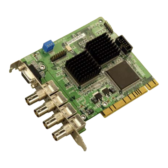
The IVC-8371P is a 4-channel Video/Audio capture card featuring multi-standard video output functionalities including high-speed transmission of MPEG4/H.263/MPEG-2 and MPEG-1 files. Empowered by its high performance MPEG-4 CODEC chip, IVC-8371P can encode and display video/audio simultaneously to achieve a real time stream of video and audio data. -
Page 9: Product Specification
IVC-8371P 1.2. Product Specification Interface Video input 4 channel NTSC/PAL/SECAM Video input type Audio Input 4 channel Audio input type Audio cable, DB9 to 3.5mm phone jack PCI v2.1 compliance PCI interface Card ID Dip-switch selectable Table 1 Interface Video Processing... -
Page 10: Package Contents
Power Consumption 7.5W, 1.5A@5V Table 6 Operation Environment 1.3. Package Contents A. IVC-8371P capture card x 1pcs B. DB-9-to-3.5mm phone jet audio cable x 1pcs C. Driver and Utility CD x 1pcs D. Quick Installation Guide x 1pcs Figure 1... -
Page 11: System Requirements
IVC-8371P 1.4. System Requirements IBM or IBM compatible computer For single IVC 8371P: Pentium 3,1.0GHz CPU For more than one IVC 8371P: Pentium 4,2.0 GHz CPU, or better processor for reasonable display quality Minimum 256MB memory AGP compatible Super VGA video card supporting DirectX and YUV mode video... -
Page 12: Dimensions
IVC-8371P User Manual 1.5. Dimensions Figure 2 Board Dimensions Page 12 ® Technology, Corp. -
Page 13: Chapter 2 Installation
IVC-8371P Chapter Installation Page 13... -
Page 14: Hardware Installation
IVC-8371P User Manual 2. Installation 2.1. Hardware Installation 2.1.1. Installing IVC-8371P Step 1. Power off the computer and remove the external power cord from the computer. Remove the chassis cover. Figure 3 Removing Chassis Cover Step 2. Locate an unoccupied PCI expansion slot on the main board/ backplane. -
Page 15: Figure 5 Installing Ivc-8371P To A Pci Slot
PCI slots. Step 4. Fasten the mounting bracket of IVC-8371P to the chassis. Step 5. If you are installing more than one IVC-8371P at a time, please repeat steps 2 to NOTE: Make sure that every IVC-8371P card in the same system is assigned with a unique ID. -
Page 16: Figure 6 Id Dip Switch
ID DIP Switch Step 6. Put the cover back to the chassis. Connect the audio cable(s) to the IVC-8371P. Each 3.5mm phone jet input Step 7. maps to a specific video channel. There is channel number indicator located near each 3.5mm phone jet of the audio cable. The channel numbers of video input are diagrammed below. -
Page 17: Figure 8 Sample Topology
The configuration adapting four IVC-8371P cards to a system powered by a Pentium 4 2.0GHz CPU has been tested and proved effective. Attaching more than 4 IVC-8371P cards to a system has not been tested and therefore is not recommended. -
Page 18: Installing Gpio Module
IVC-8371P User Manual 2.1.2. Installing GPIO Module The GPIO module contains a GPIO daughter board, an input connector and an output connector. The GPIO module allows users to connect four input devices and four output devices. Please refer to the diagram below for more details. -
Page 19: Figure 10 Gpio Installation
Connecting GPIO Module to IVC-8371P Step 1. Remove the output connector and input connector from the GPIO daughter board. Step 2. Combine the GPIO daughter board to the IVC-8371P using the CN4 connector. The locations of connectors are shown below: Figure 10 GPIO Installation For details about pin definitions of the GPIO card, please refer to Appendix A. -
Page 20: Driver Installation
IVC-8371P User Manual 2.2. Driver Installation Step 1. After you have installed IVC-8371P card onto your computer, turn on the power. Step 2. Run the product utilities CD. Select “Install Device Driver”. Page 20 ® Technology, Corp. - Page 21 IVC-8371P An installation wizard should start automatically and guide your through the Step 3. installation process. Follow the instructions on the installation wizard to proceed with the installation process. Page 21...
-
Page 22: Verify Installation
Install the device driver again. Uninstalling the old driver is also required before driver upgrade. 2.3. Verify Installation After the driver has been installed successfully, you should be able to see IVC-8371P listed in the device manager window. Page 22 ®... - Page 23 IVC-8371P Page 23...
-
Page 24: Ffdshow Video Codec Installation
IVC-8371P User Manual 2.4. FFDSHOW Video CODEC Installation FFDSHOW video codec must be installed to the system before using IVC-8371P. FFDSHOW is a DirectShow and VFW codec for decoding/encoding many video and audio formats, including DivX and XviD movies using libavcodec, xvid and other open- source libraries with a rich set of post-processing filters. - Page 25 IVC-8371P Run the FFDshow configuration at Start Programs ffdshow Configuration Page 25...
- Page 26 IVC-8371P User Manual Select the “Codecs” item from the menu bar on the left. Change the decoder options of XviD, DivX3, DivX4, DivX5, H.263 (+), MPEG1 and MPEG2 to “libavcodec.” Click to save the configuration. Page 26 ® Technology, Corp.
-
Page 27: Run Demo Program
IVC-8371P 2.5. Run Demo Program Run the demo program at Start Programs IEI IVC-8371P IVC-8371 demo program Sample user interface image captured from the IVC-8371P demo application Page 27... - Page 28 IVC-8371P User Manual Chapter Demo Program Page 28 ® Technology, Corp.
-
Page 29: Chapter 3 Demo Program
IVC-8371P 3. Demo Program The user interface of demo program can be divided into seven functional areas. 3.1. Menu 3.1.1. File Menu Exit: terminates the demo program. Page 29... -
Page 30: Encoder
IVC-8371P User Manual 3.1.2. Encoder Encoder Start: Starts recording. Encoder Stop: Stops recording. 3.1.3. Decoder Decoder Start: Starts displaying the recorded video. Decoder Stop: Stops displaying the recorded video. 3.1.4. View The view menu controls the layout of the program UI. Functional windows or video display layout can be activated or modified by checking the corresponding item on the view menu. -
Page 31: Gpio
IVC-8371P 3.1.6. GPIO Output GPIO: sends signals to GP output. Device select: Selection device card. Output 1: defines the signal (on/off) to be sent to output 1. Output 2: defines the signal (on/off) to be sent to output 2. Output 3: defines the signal (on/off) to be sent to output 3. -
Page 32: Help
IVC-8371P User Manual Device select: Selects a capture card with its specific ID to read from. Input: the value read from the GP input will be shown here after pressing the Read button. 3.1.7. Help About: Displays company information and application version. -
Page 33: Toolbar
IVC-8371P 3.2. Toolbar Toolbar includes the frequently used function of demo program. These functions can be divided into five sets. Start encoding Start decoding Stop encoding Stop decoding Display live video Configuration dialog Display playback video Set Immediate Parameters Load configuration file Most of the functional parameters such as encoding format, frame rate and motion detection, etc. -
Page 34: Video Area
IVC-8371P User Manual 3.3. Video Area Live monitoring or playback video will be displayed on the video area. There are seven layout options available as diagrammed below. Figure 11 Video Area 3.4. System Log Window The system log window shows the encoding file size and board operate information. -
Page 35: Encode / Decode Info Window
IVC-8371P 3.5. Encode / Decode Info Window This progress bar shows recording file size in Kbps. The file size is an average value summed up from the latest 100 frames. Page 35... -
Page 36: Playback Control
IVC-8371P User Manual 3.6. Playback Control NOTE: Only MPEG-4 files (indicated by the “.ps” extension name) can be played by the demo program. PLAY: Play PS file. PAUSE: Pause PS file proceed. STOP: Stop playing PS file. F/B: Fast rewind. -
Page 37: Chapter 4 Encoding & Decoding
IVC-8371P Chapter Encoding & Decoding Page 37... -
Page 38: Encoding Start And Stop
IVC-8371P User Manual 4. Encoding & Decoding 4.1. Encoding Start and Stop To encode video and audio, follow the procedures below: Step 1. Set encoder parameter on the configuration dialog. Step 2. Click in the toolbars to start encode. The recorded file will be stored in the same folder as the application program file as default, or specify in the configuration dialog. -
Page 39: Decoding Start And Stop
IVC-8371P 4.2. Decoding Start and Stop To decode the encoded video file, follow the procedure below: Step 1. Click Set display window to playback. Step 2. Set decoding parameters on the configuration dialog. Step 3. Click in the toolbar then select the encoded video file to be decoded. - Page 40 IVC-8371P User Manual Chapter Configuration Dialog Page 40 ® Technology, Corp.
-
Page 41: Chapter 5 Configuration Dialog
IVC-8371P 5. Configuration Dialog 5.1. Encoder Parameters Tab Page 41... -
Page 42: Global Parameters
Video Format: Choose the input video system (PAL/NTSC). I Reference: on/off NOTE: Global parameters will be applied to all IVC-8371P cards, if there are more than one, in the same system. 5.1.2. Encoder Parameters Device Selection: Select the target card to be configured Resolution: Configure video size. -
Page 43: Table 8 Options Table For Pal
IVC-8371P Options Table for PAL (Phase Alternation Line) Resolution Options Total Maximum Frame Rate 720x576 25fps 720X288 50fps 360X288 100fps 640x576 25fps 640x288 50fps 320x288 100fps Table 8 Options Table for PAL Encoding Bit Rate: CBR(Constant Bit Rate) or VBR(Variable Bit Rate) -
Page 44: Decoder Parameters
IVC-8371P User Manual 5.2. Decoder Parameters Page 44 ® Technology, Corp. -
Page 45: Device Selection
IVC-8371P 5.2.1. Device Selection Select the target device to be configured. 5.2.2. Video Parameters Decoding Channel: Default Multi Channel. De-interlace: Enable de-interlace. I Reference: Enable I Reference. Encoding Standard Display: Enable Standard Display. 5.2.3. Audio Parameters Decoding Channel: Select the channel to be decoded. -
Page 46: Set Video Decoder
IVC-8371P User Manual 5.3. Set Video Decoder Page 46 ® Technology, Corp. -
Page 47: Device Selection
IVC-8371P 5.3.1. Device Selection Device Selection: Select the target device to be configured 5.3.2. Set Video Decoder Controller AGC, Hue, Saturation, Contrast and Brightness can be configured for each channel respectively. Default value: AGC = on, HUE = 0, SATURATION = 80,... -
Page 48: Set Motion Detection
IVC-8371P User Manual 5.4. Set Motion Detection Page 48 ® Technology, Corp. -
Page 49: Device Selection
IVC-8371P 5.4.1. Device Selection Device Selection: Select the target device to be configured 5.4.2. Set Motion Detection Parameters Enable motion detection for the corresponding channel Sensitivity: Set the sensitivity of detection level. Small value has more sensitivity. Default: Reset sensitivity value to default. -
Page 50: Appendix A Gpio Connection
IVC-8371P User Manual Appendix GPIO Connection Page 50 ® Technology, Corp. -
Page 51: Figure 12 Gp Input Connection
IVC-8371P GP Input Connection: An input connector and an output connector are provided for connections to external devices. The connection points of the input connector are shown in the figure below. Figure 12 GP Input Connection Connection: Please connect the “COM” on the sensor to the “Input”. -
Page 52: Figure 14 Gp Output Connection
IVC-8371P User Manual GP Output Connection: The connection points of the output connector are shown in the figure below. Figure 14 GP Output Connection Operation procedure: The active state of DVR software configuration is Normal Open. Com and NC should have signals before and after system is turned on. -
Page 53: Table 9 General Input Voltages
IVC-8371P Specification for General Inputs The general inputs support DC voltage from 0~24V. Voltage of above 24V is not recommended. Voltage Range Logic 0 < 0.5V Logic 1 0.5V – 24V Table 9 General Input Voltages Specification for General Outputs... -
Page 54: Appendix B Faq
IVC-8371P User Manual Appendix Page 54 ® Technology, Corp. - Page 55 Can IVC-8371P card driver be upgraded directly after first installation? No. To upgrade or re-install IVC-8371P device driver, or to add more IVC-8371P card into the system, you have to remove the existing IVC-8371P device driver and reboot the system.
- Page 56 When multiple cards are inserted at the same time, can the same ID be assigned to them? No. A unique card ID has to be assigned to each card for IVC-8371P to identify which channels the device is mapped to. Identical card ID may cause system malfunctioning.
- Page 57 IVC-8371P Index Page 57...
- Page 58 IVC-8371P User Manual Frame Rate ..........43 A G AGC ............47 Audio............43 Global Parameters ........42 audio cable ..........16 GOP Structure........... 43 Audio Input...........9 GP Input Connection......... 51 Audio Parameters ........45 GP Output Connection......51 AVI file............55 GPIO ............31 GPIO Connection........
- Page 59 IVC-8371P Power Consumption ........10 T Pre-Processing ..........43 product utilities CD........20 Toolbar ............33 PS file ............55 V Q Video Area ..........34 Quality............43 video channel..........16 Quantization..........9 Video CODEC........... 24 Video Compression ........9 R Video Decoder .......... 46 Video Decoder Controller......47 Relay Coil Specifications ......53...
Need help?
Do you have a question about the IVC-8371P and is the answer not in the manual?
Questions and answers