Table of Contents
Advertisement
Quick Links
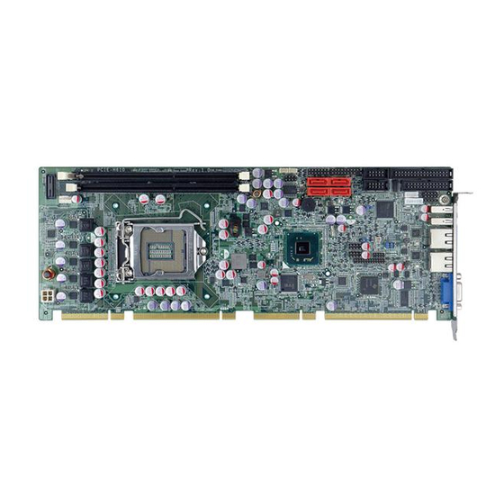
Full-size PICMG 1.3 CPU Card supports 32nm LGA1155
Intel® Core™ i7/i5/i3 CPU per Intel® H61, DDR3, VGA,
Dual Realtek PCIe GbE, USB 2.0, SATA 3Gb/s, HD Audio
Quick Installation Guide
Package Contents
PCIE-H610 package includes the following items:
1 x PCIE-H610 Single Board Computer
1 x Dual RS-232 Cable (P/N:19800-000051-RS)
4 x SATA Cable (P/N:32000-0628000-RS)
1 x USB Cable (P/N: CB-USB02-RS)
1 x DVI and USB Kit (P/N:IO-KIT-001-R20)( DVI SKU only)
1 x Mini Jumper Pack
1 x Utility CD
1 x QIG (Quick Installation Guide)
and RoHS
PCIE-H610
Version 1.02
Dec. 05, 2012
© 2006 Copyright by IEI Technology corp.
All rights reserved.
1
Advertisement
Table of Contents

Subscribe to Our Youtube Channel
Related Manuals for IEI Technology PCIE-H610


Summary of Contents for IEI Technology PCIE-H610
- Page 1 Dual Realtek PCIe GbE, USB 2.0, SATA 3Gb/s, HD Audio and RoHS PCIE-H610 Quick Installation Guide Version 1.02 Dec. 05, 2012 Package Contents PCIE-H610 package includes the following items: 1 x PCIE-H610 Single Board Computer 1 x Dual RS-232 Cable (P/N:19800-000051-RS) 4 x SATA Cable (P/N:32000-0628000-RS) ...
-
Page 2: Specifications
Specifications CPU LGA1155 socket supports Intel® Core™ i7/i5/i3 /Pentium® /Celeron® processor System Chipset: Intel® H61 BIOS: UEFI BIOS System Memory: Two 240-pin 1333/1066MHz dual-channel DDR3 & DDR3L(1.35V) DIMMs supported.(system max. 16GB) Graphic: VGA Integrated in Intel® H61 ... -
Page 3: Ordering Information
Dimensions: 338mm X 126mm Weight: 1.2Kg Ordering Information PCIE-H610-R10: Full-size PICMG 1.3 CPU Card supports 32nm LGA1155 Intel® Core™ i7/i5/i3 CPU per Intel® H61, DDR3, VGA, Dual Realtek PCIe GbE, USB 2.0, SATA 3Gb/s, HD Audio and RoHS PCIE-H610-DVI-R10: Full-size PICMG 1.3 CPU Card supports 32nm... - Page 4 CPU-DT-i5-2390T: Intel® Core™ i5-2390T processor, LGA1155, Dual core 2.7GHz, 3M Cache, 35W, AMT, compatible with CF-1156C-RS CPU cooler CPU-DT-i3-2120T: Intel® Core™ i3-2120T processor, LGA1155, Dual core 2.6GHz, 3M Cache, 35W, compatible with CF-1156C-RS CPU cooler CPU-DT-P-G630T: Intel® Pentium G630T processor, LGA1155, Dual core 2.3GHz, 3M Cache, 35W, compatible with CF-1156C-RS CPU cooler CPU-DT-C-G440: Intel®...
-
Page 5: Jumpers Setting And Connectors
Jumpers setting and Connectors Table of Jumpers LABEL FUNCTION J_CMOS1 CMOS state setting WOL_SEL1 WOL Enable setting JATX_AT1 Power Mode Setting Table of Connectors LABEL FUNCTION VGA1 VGA 15-pin Female Connector USB_C1 USB Port Connector USB_C2 LAN1 、 LAN2 RJ45 LAN Connector KB_MS1 Internal PS/2 KEYBOARD/MOUSE Connector COM1... -
Page 6: Jumper Setting
Jumper setting J_CMOS1 : Clear CMOS setting Jumper J_CMOS1 DESCRIPTION Normal (Default) Clear CMOS Data JATX_AT1 : Power Mode Setting by ATX or AT JATX_AT1 DESCRIPTION ATX Power Mode (ON) AT Power Mode (OFF) JLAN_PWR1 : WOL enable jumper PIN NO. DESCRIPTION PIN NO. - Page 7 USB_C01,USB_C02 PIN NO. DESCRIPTION DATA- DATA+ GROUND LAN1、LAN2: RJ45 LAN Connector PIN NO. DESCRIPTION PIN NO. DESCRIPTION MDIA3- MDIA1+ MDIA3+ MDIA2+- MDIA2- MDIA0- MDIA1- MDIA0+ MS/KB1: Internal 6-pin Keyboard Connector DESCRIPTION VCC(+5V) Mouse Data Mouse Clock Keyboard Data Keyboard Clock Ground COM1,COM2: Internal Serial Port Connector DESCRIPTION...
- Page 8 J_AUDIO1 : External Audio Module Connector PIN DESCRIPTION DESCRIPTION ACZ_BITCLK ACZ_SYNC ACZ_SDOUT ACZ_PCBEEP ACZ_SDIN ACZ_RST# ACZ_VCC(+5V) ACZ_GND ACZ_12V ACZ_GND SATA1-SATA4 : Serial ATA Connector DESCRIPTION DESCRIPTION IR1: IrDA connector PIN NO. DESCRIPTION IR-RX IR-TX...
- Page 9 FDD1: Floppy Disk Drive Connector DESCRIPTION DESCRIPTION REDUCE WRITE INDEX# MOTOR ENABLE A# DRIVE SELECT B# DRIVE SELECT A# MOTOR ENABLE B# DIRECTION# STEP# WRITE DATA# WRITE GATE# TRACK 0# WRITE PROTECT# READ DATA# SIDE 1 SELECT# DISK CHANGE# LPT1 : Parallel Port Connector DESCRIPTION DESCRIPTION STROBE#...
- Page 10 DVI Connector (DVI SKU only) PIN NO. DESCRIPTION PIN NO. DESCRIPTION Data 2- Data 2+ Hot Plug Detect. Data 0- Data 0+ DDC Clock DDC Data Data 1- Data 1+ Clock + Clock - CPU_FAN1 : CPU Fan Connector PIN NO. DESCRIPTION Ground +12V...
- Page 11 F_PANEL1 : External Switches and Indicators panel PIN DESCRIPTION PIN DESCRIPTION Power LED Speaker GROUND PWRBTN+ Speaker PWRBTN PWRBTN- Reset- RESET HDDLED HDLED- CPU12V1: ATX-12V CPU Power Input connector PIN NO. DESCRIPTION PIN NO. DESCRIPTION +12V +12V I2C_1 PIN NO. DESCRIPTION PCH_GP38_PU PCH_GP39_PU...
- Page 12 TPM1 Connector PIN NO. DESCRIPTION PIN NO. DESCRIPTION FRAME# RERST# SMB_CLK SMB_DATA SB3V SERIRQ CLKRUN# PM_SUS_STAT# DRQ# COM3: External Serial Port Connector ( RS422/485 ) PIN NO. DESCRIPTION PIN NO. DESCRIPTION RXD485# TXD485+ RXD485+ TXD485# ● ● ● ■...
-
Page 13: Board Layout: Jumper And Connector Locations
Board Layout: Jumper and Connector Locations...
Need help?
Do you have a question about the PCIE-H610 and is the answer not in the manual?
Questions and answers