
Subscribe to Our Youtube Channel
Related Manuals for Beckhoff KM6551


Summary of Contents for Beckhoff KM6551
- Page 1 Documentation | EN KM6551 Terminal module for wireless data exchange 2021-03-03 | Version: 2.0.0...
-
Page 3: Table Of Contents
ZS6201-0500 ........................ 36 5 Application examples - overview ...................... 38 Peer to peer mode ........................... 38 Master-Slave mode ......................... 38 Broadcast mode .......................... 39 Energy scan............................. 40 6 TwinCAT .............................. 42 TwinCAT libraries .......................... 44 TwinCAT examples ......................... 44 Function blocks.......................... 45 6.3.1 Function block FB_KM6551_MAIN.................. 45 KM6551 Version: 2.0.0... - Page 4 Example 1: reading the firmware version from Register 9.......... 65 8.5.2 Example 2: Writing to an user register................ 66 9 Appendix .............................. 69 General operating conditions...................... 69 EC declaration of conformity ...................... 71 Calculating with decibels ......................... 72 Support and Service ........................ 72 Version: 2.0.0 KM6551...
-
Page 5: Foreword
EP1590927, EP1789857, EP1456722, EP2137893, DE102015105702 with corresponding applications or registrations in various other countries. ® EtherCAT is registered trademark and patented technology, licensed by Beckhoff Automation GmbH, Germany. Copyright © Beckhoff Automation GmbH & Co. KG, Germany. The reproduction, distribution and utilization of this document as well as the communication of its contents to others without express authorization are prohibited. -
Page 6: Safety Instructions
All the components are supplied in particular hardware and software configurations appropriate for the application. Modifications to hardware or software configurations other than those described in the documentation are not permitted, and nullify the liability of Beckhoff Automation GmbH & Co. KG. Personnel qualification This description is only intended for trained specialists in control, automation and drive engineering who are familiar with the applicable national standards. -
Page 7: Documentation Issue Status
WW - week of production (calendar week) 35 - week of production 35 YY - year of production 05 - year of production 2005 FF - firmware version 00 - firmware version 00 HH - hardware version 01 - hardware version 01 KM6551 Version: 2.0.0... -
Page 8: Product Overview
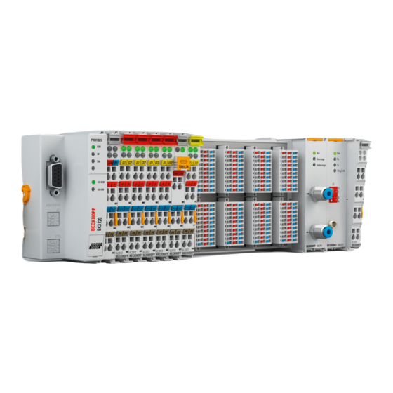
Introduction Fig. 1: KM6551-0000 - Terminal module for radio transmission The KM6551-0000 terminal module is a data exchange unit based on radio technology. It uses the IEEE 802.15.4 standard. Data is exchanged or transmitted between two independent controllers via radio, independent of the higher-level fieldbus. The free-field distance between two KM6551-0000 units can be up to 300 m. -
Page 9: Technical Data
Current consumption via K-bus typically 135 mA Width of a bus terminal block Maximum 64 standard Bus Terminals or 80 cm (one KM6551-0000 corresponds to 2 standard Bus Terminals here) Data width in the input process image 12 bytes Data width in the output process image 12 bytes... -
Page 10: Basic Function Principles
It uses the IEEE 802.15.4 standard as its basis with a Beckhoff-specific protocol. 10 bytes of user data are transmitted per data packet. The DIP switch is used to set the operating mode of the KM6551-0000, i.e. whether the module functions as a master or slave and which communication mode is to be used. -
Page 11: Fig. 3 Peer To Peer
Mode 2: Master-slave – data exchange between a master and up to 7 slaves In master-slave mode the master can communicate with up to seven KM6551-0000 using the polling method. To do this, set the corresponding slave addresses using the DIP switch. From the PLC you can inform the master which slave it should communicate with, how often and for how long. -
Page 12: Led Displays
Couplers on request). All Bus Terminal Controllers from the BCxxxx, BXxxxx and BXxxxx series are supported. NOTE CE conformity The CE conformity of the KM6551-0000 is only guaranteed if it is operated with original Beckhoff acces- sories (antennas [} 27], coaxial cable [} 19])! LED displays KM6551-0000 Fig. 6: KM6551 - LED displays... -
Page 13: Dip Switch
Red - poor signal quality or watchdog has triggered DIP switch You can activate the different modes of the KM6551-0000 using the DIP switch. This enables the simple exchange of the modules without additional configuration software. • DIP switch in right position: ON •... -
Page 14: Ieee802.15.4
However, it is worth mentioning in this respect that the IEEE 802.15.4 standard is in no way linked to the ZigBee Alliance. No ZigBee! The KM6551-0000 data transmission module is based on IEEE 802.15.4, but it is not a ZigBee product and is also not ZigBee-compatible! Technical data... -
Page 15: Interference Caused By Other Radio Systems
• Microwave ovens WLAN If the IEEE 802.15.4 channel used by the KM6551-0000 and the frequency range of a neighboring WLAN network overlap, this can lead to disruptions in the KM6551-0000 communication. Select an IEEE 802.15.4 channel for the KM6551-0000 that uses the gaps between neighboring WLAN networks as shown in the figure below. - Page 16 Microwave ovens Since microwave ovens typically operate at a frequency of 2.455 GHz, neighboring poorly screened ovens can interfere with the transmission between the KM6551-0000. In this case, remove the interfering devices or use only well-screened microwave ovens in the direct vicinity of the KM6551-0000.
-
Page 17: Mounting And Wiring
Risk of electric shock and damage of device! Bring the bus terminal system into a safe, powered down state before starting installation, disassembly or wiring of the Bus Terminals! Mounting • Fit the mounting rail to the planned assembly location. KM6551 Version: 2.0.0... - Page 18 • Lever the unlatching hook on the left-hand side of the terminal module upwards with a screwdriver (3). As you do this ◦ an internal mechanism pulls the two latching lugs (3a) from the top hat rail back into the terminal module, ◦ the unlatching hook moves forwards (3b) and engages Version: 2.0.0 KM6551...
-
Page 19: Dimensions
• Pull (4) the terminal module away from the mounting surface. Dimensions Fig. 10: KM6551 dimensions Connection The antennas are connected via a reverse SMA screw plug. Please screw the cable, the coaxial cable or the antenna hand tight to this screw plug. - Page 20 Coaxial cable Name Description ZK6000-0102-0020 Coaxial cable, characteristic impedance 50 Ω, preassembled plug connectors (SMA plug and reverse SMA socket), black, 2 m ZK6000-0102-0040 Coaxial cable, characteristic impedance 50 Ω, preassembled plug connectors (SMA plug and reverse SMA socket), black, 4 m Version: 2.0.0 KM6551...
-
Page 21: Antenna Alignment
Omnidirectional antennas ZS6201-0410, ZS6201-0500 Design Side view Top view (vertical directional characteristic) (horizontal directional characteristic) ZS6200-0400 Predestined for mounting below the ceiling. Design Side view Top view (vertical directional characteristic) (horizontal directional characteristic) KM6551 Version: 2.0.0... - Page 22 Mounting and wiring Directional antennas ZS6100-0900 Design Side view Top view (vertical directional characteristic) (horizontal directional characteristic) ZS6100-1800 Design Side view (vertical directional characteristic) Top view (horizontal directional characteristic) Version: 2.0.0 KM6551...
-
Page 23: Alignment Examples
For optimum transmission, the antennas of all of the KM6551-0000 used must have the same polarization. Omnidirectional antennas Care must also be taken when using omnidirectional antennas that the antennas of all of the KM6551-0000 used have the same polarization. -
Page 24: Placement Of The Antennas
Fresnel zone! The connection of the antennas [} 27] to the KM6551-0000 via the RSMA plug and coaxial cable [} 19] enables the antenna to be mounted remotely, so that you can position the antenna optimally. -
Page 25: Attenuation And Range
Reception may then be disturbed or completely interrupted under certain circumstances. If the Fresnel zone is free from obstructions, the propagating wave is only attenuated by the free space attenuation. Fig. 15: Radius r of the Fresnel zone in relationship to the distance s KM6551 Version: 2.0.0... -
Page 26: Attenuation In Practice
The given ranges are based on an unobstructed view and adherence to the Fresnel zone. Two omnidirectional antennas Fig. 16: Two omnidirectional antennas Omnidirectional antenna combined with a directional antenna Fig. 17: Omnidirectional antenna combined with a directional antenna Version: 2.0.0 KM6551... -
Page 27: Antennas
Rod antenna (gain 4 dBi), with cable (1 m) ZS6201-0410 [} 34] Rod antenna (gain 5 dBi), without cable ZS6201-0500 [} 36] NOTE CE conformity The CE conformity of the KM6551-0000 is only guaranteed if it is operated with original Beckhoff acces- sories (antennas, coaxial cable [} 19])! KM6551 Version: 2.0.0... -
Page 28: Fig. 19 Zs6100-0900 - Directional Antenna
Mounting and wiring 4.7.1 ZS6100-0900 Fig. 19: ZS6100-0900 - Directional antenna Fig. 20: ZS6100-0900 - Azimuth and Elevation for 2400 MHz Version: 2.0.0 KM6551... - Page 29 Permissible ambient temperature range during -40°C ... + 80°C operation Permissible relative air humidity 95%, no condensation Protection class IP20 Installation position variable Approval Mounting Bracket mounting, included in scope of supply Suitable coaxial cable ZS6000-0102-0020, ZS6000-0102-0040 KM6551 Version: 2.0.0...
-
Page 30: Fig. 21 Zs6100-1800 - Directional Antenna With Large Gain
Mounting and wiring 4.7.2 ZS6100-1800 Fig. 21: ZS6100-1800 - Directional antenna with large gain Fig. 22: ZS6100-1800 - Azimuth and Elevation for 2400 MHz Version: 2.0.0 KM6551... - Page 31 Permissible ambient temperature range during -40°C ... + 80°C operation Permissible relative air humidity 95%, no condensation Protection class IP20 Installation position variable Approval Mounting Bracket mounting, included in scope of supply Suitable coaxial cable ZS6000-0102-0020, ZS6000-0102-0040 KM6551 Version: 2.0.0...
-
Page 32: Fig. 23 Zs6200-0400 - Omnidirectional Antenna
Mounting and wiring 4.7.3 ZS6200-0400 Fig. 23: ZS6200-0400 - Omnidirectional antenna Fig. 24: ZS6200-0400 - Azimuth and Elevation for 2400 MHz Version: 2.0.0 KM6551... - Page 33 Weight (incl. accessories and packaging) approx. 210 g Permissible ambient temperature range during -40°C ... + 80°C operation Permissible relative air humidity 95%, no condensation Protection class IP20 Installation position variable, predestined for mounting below the ceiling. Approval Suitable coaxial cable ZS6000-0102-0020, ZS6000-0102-0040 KM6551 Version: 2.0.0...
-
Page 34: Fig. 25 Zs6201-0410 - Rod Antenna With Cable
Mounting and wiring 4.7.4 ZS6201-0410 Fig. 25: ZS6201-0410 - Rod antenna with cable Fig. 26: ZS6201-0410 - Azimuth and Elevation for 2400 MHz Version: 2.0.0 KM6551... - Page 35 Permissible ambient temperature range during -40°C ... + 80°C operation Permissible relative air humidity 95%, no condensation Mounting Cap nut M14 Protection class IP20 Installation position variable Approval Coaxial cable 1 m, included in scope of supply KM6551 Version: 2.0.0...
-
Page 36: Fig. 27 Zs6201-0500 - Rod Antenna
Mounting and wiring 4.7.5 ZS6201-0500 Fig. 27: ZS6201-0500 - Rod antenna Fig. 28: ZS6201-0500 - Azimuth and Elevation for 2400 MHz Version: 2.0.0 KM6551... - Page 37 Permissible ambient temperature range during -40°C ... + 80°C operation Permissible relative air humidity 95%, no condensation Mounting Direct connection with hinged joint Protection class IP20 Installation position variable Approval Suitable coaxial cable Not required, direct connection KM6551 Version: 2.0.0...
-
Page 38: Application Examples - Overview
• Energy scan [} 40] Peer to peer mode Application The simplest type of communication between two KM6551-0000 is the peer to peer mode. To do this, set the DIP switches [} 13] • of the master module to master mode and •... -
Page 39: Broadcast Mode
CB1.6 CB1.5 CB1.4 CB1.3 CB1.2 CB1.1 CB1.0 Name RegAccess reserve Add3 Add2 Add1 Scan EnergyScan Start Value SB1 [} 59] SB1.7 SB1.6 SB1.5 SB1.4 SB1.3 SB1.2 SB1.1 SB1.0 Name RegAccess Error Add3 Add2 Add1 Scan EnergyScan Start Value KM6551 Version: 2.0.0... -
Page 40: Energy Scan
0...0xF; "0" means no energy, "0xF" or 16dec stands for high energy level. Set bit 1 in CB1 to TRUE. The KM6551-0000 confirms this in the status with bit 1, which is then also set to TRUE. - Page 41 Application examples - overview SB1 [} 59] SB1.7 SB1.6 SB1.5 SB1.4 SB1.3 SB1.2 SB1.1 SB1.0 Name RegAccess Error Add3 Add2 Add1 Scan EnergyScan Start Value KM6551 Version: 2.0.0...
-
Page 42: Twincat
The general use of hardware and software from the open PC world requires some checking: Unsuitable components can upset the PC system. Beckhoff integrates a handy display of the real-time jitter in order to provide administrators with a simple means of evaluating hardware and software. A system message during operation can draw attention to error states. - Page 43 According to the requirement for operating resources, the TwinCAT software devices can be distributed: TwinCAT PLC programs can be executed on PCs and on Beckhoff Bus Terminal controllers. A "message router" manages and distributes all the messages, both in the system and via TCP/IP connections. PC systems can be connected to one another by TCP/IP;...
-
Page 44: Twincat Libraries
TwinCAT TwinCAT libraries A TwinCAT library is available for all Beckhoff controller families (BC, BX, CX and IPC) for the operation of the KM6551-0000 under TwinCAT. This library takes care of communication with the terminal. It sets parameters in or reads parameters from the terminal. The use of the library simplifies communication with the terminal for the user. -
Page 45: Function Blocks
:E_KM6551_ERRORID; bBusy :BOOL; strLinkData :KM6551_Data; b Active: The function block has successfully transmitted the parameters to KM6551-0000 and can now commence data communication with the other KM6551-0000 function blocks. bError: The function block has an error. iErrorID: Contains the error code. -
Page 46: Energy Scan
0...0xF; "0" means no energy, "0xF" or 16dec stands for high energy level. Set bit 1 in CB1 to TRUE. The KM6551-0000 confirms this in the status with bit 1, which is then also set to TRUE. -
Page 47: Master/Slave Mode
The address of the slave is entered here (see DIP switch on your slave module) strLinkData: Is linked with strLinkData from FB_KM6551_MAIN. ptData_IN: Pointer to the variable into which the device data should be copied (pointer address is KM6551 Version: 2.0.0... -
Page 48: Fig. 31 Function Block Fb_Km6551_Slave_10Byte
- the LQI value should be as high as possible and should have a minimum value of 10 - 20. You can improve the LQI value by the use of better antennas or shorter cables or better alignment of the antennas. E_Addr: Reads out the DIP switch setting of the KM6551-0000 module and displays it. 6.3.3.2 Function block FB_KM6551_SLAVE_10BYTE This function block takes care of communication to the slave module. -
Page 49: Broadcast Mode
The length can be determined with SIZEOF and must not be larger than 10 bytes. The strLinkData variable is linked to the FB_KM6551_MAIN function block (the variable has exactly the same name). The FB_KM6551_MAIN function block should be finished before the FB_KM6551_MASTER_10BYTE function block is called, (see bActive in this function block). KM6551 Version: 2.0.0... -
Page 50: Fig. 32 Function Block Fb_Km6551_Masterbroadcast_10Byte
Error: The function block has an error. bActive: Indicates whether or not the function block is working. iErrorID: Contains the error code. E_Addr: Reads out the DIP switch setting of the KM6551-0000 and displays it. 6.3.4.2 Function block FB_KM6551_SLAVEBROADCAST_10BYTE This function block takes care of communication to the broadcast slave module. -
Page 51: Fig. 33 Function Block Fb_Km6551_Slavebroadcast_10Byte
- the LQI value should be as high as possible and should have a minimum value of 10 - 20. You can improve the LQI value by the use of better antennas or shorter cables or better alignment of the antennas. E_Addr: Reads out the DIP switch setting of the KM6651-0000 module and displays it. KM6551 Version: 2.0.0... -
Page 52: Ks2000 Configuration Software
Fieldbus Box modules with the aid of which settings can be modified easily. Alternatively, you have full access to all internal registers of the bus couplers and intelligent terminals. Refer to the register description for the meanings of the registers. Version: 2.0.0 KM6551... -
Page 53: Parameterization With Ks2000
Click on the Login button. The configuration software will now load the information for the connected fieldbus station. In the example shown, this is • a BK9000 Bus Coupler for Ethernet • a KL1002 input terminal • a KM6551-0000 data exchange terminal • a KL9010 Bus End Terminal KM6551 Version: 2.0.0... -
Page 54: Fig. 35 Display Of The Fieldbus Station In Ks2000
The tree branches Register, Settings and ProcData are displayed for the KM6551-0000: • Register [} 56] allows direct access to the registers of the KM6551-0000. • Under settings [} 55] you will find dialog masks for parameterizing the KM6551-0000. • Process data [} 57] shows the process data of the KM6551-0000. -
Page 55: Settings
KS2000 Configuration Software Settings Dialog screen for parameterizing the KM6551. Fig. 37: Dialog screen for parameterizing the KM6551 Settings Radio channel for KM6551 (R33) R33 [} 64] Here you can set the radio channel. (Default: 5, permissible values: 0 to 15). Scan settings Found slaves Displays the number of slaves found (R40 [} 64]). -
Page 56: Register
KS2000 Configuration Software Register Under Register you can directly access the registers of the KM6551-0000 terminal module. The meaning of the register is explained in the Register overview [} 62]. Fig. 38: Register view in KS2000 Version: 2.0.0 KM6551... -
Page 57: Process Data
The spectacles mark the data that are currently graphically displayed in the History field. Fig. 40: History field The current input value is displayed numerically in the Value field. Fig. 41: Value field Output values can be modified through direct input or by means of the fader control. KM6551 Version: 2.0.0... -
Page 58: Fig. 42 Value Field
After pressing the Settings button you can set the format of the numerical display to hexadecimal, decimal or binary. Fig. 43: Setting the display Version: 2.0.0 KM6551... -
Page 59: Access From The User Program
Access from the user program Access from the user program Process image The KM6551-0000 terminal module represents itself in the process image with a maximum of 12 bytes of input data and 12 bytes of output data. These are organized as follows: Format... - Page 60 SB1.5 to SB1.3 Address 1..7 Slave address 1: Slave 1 2: Slave 2 7: Slave 7 SB1.2 Scan SB1.1 EnergyScan 1 TRUE if energy scanning is active; will be reset to FALSE when the terminal has finished. SB1.0 Start Version: 2.0.0 KM6551...
-
Page 61: Register Communication
SB1.6 SB1.5 SB1.4 SB1.3 SB1.2 SB1.1 SB1.0 Name RegAccess R/W Reg. no. Name Description SB1.7 RegAccess Acknowledgment for register access SB1.6 Read access SB1.5 to SB1.0 Reg. no. Number of the register that was read or written. KM6551 Version: 2.0.0... -
Page 62: Register Overview
Network ID 0x0000 R/W RAM R41 [} 64] Wrong channel (internal) EEPROM reserved 0x0000 EEPROM Reset counter (internal) EEPROM reserved 0x0000 EEPROM Attenuation of the transmission power 0x0000 R/W EEPROM R46 [} 64] reserved 0x0000 EEPROM reserved 0x0000 EEPROM Version: 2.0.0 KM6551... -
Page 63: Register Description
[} 65]. R8: Module ID Register R8 contains the name for the terminal module. KM6551-0000: 0x1997 (6551 R9: Firmware version Register R9 contains the ASCII coding of the terminal's firmware version, e.g. 0x3141 = '1A'. '0x31' corresponds to the ASCII character '1', '0x41' corresponds to the ASCII character 'A'. - Page 64 ID to distinguish between different radio networks only if no more free channels are available! R46: Attenuation of the transmission power You can attenuate the transmission power of the KM6551-0 using bits 0000 to 7 of register R46. The setting only takes effect when the module is restarted.
-
Page 65: Examples Of Register Communication
Input Data (answer of the Bus Terminal) Byte 0: Status byte Byte 1: DataIN1, high byte Byte 2: DataIN1, low byte 0x89 0x33 0x41 Explanation: • The terminal returns the value of the control byte as a receipt in the status byte. KM6551 Version: 2.0.0... -
Page 66: Example 2: Writing To An User Register
• Bit 0.6 not set means: reading the register. • Bits 0.5 to 0.0 specify the register number 31 with 01 1111 • The output data word (byte 1 and byte 2) has no meaning during read access. Version: 2.0.0 KM6551... - Page 67 • Bit 0.6 not set means: reading the register. • Bits 0.5 to 0.0 indicate register number 32 with 10 0000 • The output data word (byte 1 and byte 2) has no meaning during read access. KM6551 Version: 2.0.0...
- Page 68 • The terminal returns a value as a receipt in the status byte that differs only in bit 0.6 from the value of the control byte. • The input data word (byte 1 and byte 2) is of no importance after the write access. Any values still displayed are invalid! Version: 2.0.0 KM6551...
-
Page 69: Appendix
Approval and use The KM6551-0000 module meets the requirements of EN 300-440-02 V1.1.2. Operation of the KM6551-0000 module is permitted in all EU countries as well as in Switzerland and Liechtenstein. Other countries on enquiry. The use of the KM6551-0000 is permitted with the following antennas:... - Page 70 A protective conductor connection to the profile rail is (VDE 0106, Part 1) necessary! Protection class conforms to IEC 529 IP20 (protection against contact with a standard test finger) Protection against foreign objects Less than 12 mm in diameter Protection against water no protection Version: 2.0.0 KM6551...
-
Page 71: Ec Declaration Of Conformity
Appendix EC declaration of conformity Fig. 44: EC declaration of conformity KM6551 Version: 2.0.0... -
Page 72: Calculating With Decibels
3 + 3 + 3 = 9 2 x 100 = 200 3 + 20 = 23 1000 / 2 = 500 30 - 3 = 27 Support and Service Beckhoff and their partners around the world offer comprehensive support and service, making available fast and competent assistance with all questions related to Beckhoff products and system solutions. Version: 2.0.0 KM6551... - Page 73 Please contact your Beckhoff branch office or representative for local support and service on Beckhoff products! The addresses of Beckhoff's branch offices and representatives round the world can be found on her internet pages: https://www.beckhoff.com You will also find further documentation for Beckhoff components there.
- Page 74 Fig. 34 KS2000 configuration software....................Fig. 35 Display of the fieldbus station in KS2000 ..................Fig. 36 KS2000 branch for channel 1 of the KM6551................Fig. 37 Dialog screen for parameterizing the KM6551 ................Fig. 38 Register view in KS2000......................
- Page 76 Beckhoff Automation GmbH & Co. KG Hülshorstweg 20 33415 Verl Germany Phone: +49 5246 9630 info@beckhoff.com www.beckhoff.com...
Need help?
Do you have a question about the KM6551 and is the answer not in the manual?
Questions and answers