
Subscribe to Our Youtube Channel
Related Manuals for Beckhoff KM2774


Summary of Contents for Beckhoff KM2774
- Page 1 Documentation | EN KM2774 Terminal module for jalousie motors 2021-03-03 | Version: 2.0.0...
-
Page 3: Table Of Contents
Register overview .......................... 27 Register description ......................... 28 Examples of Register Communication .................... 30 5.8.1 Example 1: reading the firmware version from Register 9.......... 30 5.8.2 Example 2: Writing to an user register................ 30 6 Appendix .............................. 34 Support and Service ........................ 34 KM2774 Version: 2.0.0... - Page 4 Table of contents Version: 2.0.0 KM2774...
-
Page 5: Foreword
EP1590927, EP1789857, EP1456722, EP2137893, DE102015105702 with corresponding applications or registrations in various other countries. ® EtherCAT is registered trademark and patented technology, licensed by Beckhoff Automation GmbH, Germany. Copyright © Beckhoff Automation GmbH & Co. KG, Germany. The reproduction, distribution and utilization of this document as well as the communication of its contents to others without express authorization are prohibited. -
Page 6: Safety Instructions
All the components are supplied in particular hardware and software configurations appropriate for the application. Modifications to hardware or software configurations other than those described in the documentation are not permitted, and nullify the liability of Beckhoff Automation GmbH & Co. KG. Personnel qualification This description is only intended for trained specialists in control, automation and drive engineering who are familiar with the applicable national standards. -
Page 7: Documentation Issue Status
WW - week of production (calendar week) 12 - week of production 12 YY - year of production 10 - year of production 2010 FF - firmware version 1E - firmware version 1E HH - hardware version 04 - hardware version 04 KM2774 Version: 2.0.0... -
Page 8: Product Overview
Introduction Fig. 1: KM2774 - Triac outputs for four blind motors The KM2774-0000 terminal module is used for controlling up to four motors for blinds and for connecting the associated push buttons. Three interlocked triac outputs (230 V, 1.5 A), three digital inputs (24 V) and one ground switching output (24 V, 20 mA), e.g. -
Page 9: Technical Data
Product overview Technical data Technical data KM2774-0000 Number of power outputs 4 x 3 make contacts Rated voltage of the power outputs 80 ... 230 V Overvoltage protection at the power outputs > 275 V Output current from the power outputs 1.5 A (0.6 mA no-load current) Surge current 40 A (16 ms), 3 A (30 s) -
Page 10: Mounting And Wiring
KM/EM connector simply undo 2 screws so that you can pull them off (fixed wiring)! • Lever the unlatching hook on the left-hand side of the terminal module upwards with a screwdriver (3). As you do this Version: 2.0.0 KM2774... -
Page 11: Recommended Mounting Rails
Terminal Modules und EtherCAT Modules of KMxxxx and EMxxxx series, same as the terminals of the EL66xx and EL67xx series can be snapped onto the following recommended mounting rails: • DIN Rail TH 35-7.5 with 1 mm material thickness (according to EN 60715) • DIN Rail TH 35-15 with 1,5 mm material thickness KM2774 Version: 2.0.0... -
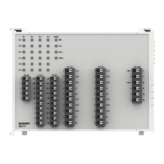
Page 12: Wiring
Ground the 0 V potentials of the 24 V supply voltage. Connect • the 0 V potential of the supply voltage (Us) of the Bus Coupler that controls the KM2774-1001 and • the 0 V potential of the KM2774-1001 supply voltage (X0, terminal point 3, 4 or 5) with the protective earth. - Page 13 Channel 3: Input for button 3 Channel 3: Switched ground for button LED X4: Ch4 24 V Channel 4: 24 V for push button Channel 4: Input for button 1 Channel 4: Input for button 2 Channel 4: Input for button 3 Channel 4: Switched ground for LED KM2774 Version: 2.0.0...
- Page 14 Channel 4: Protective earth for motor 4 Connection for supply voltage (230 V) Terminal strip Terminal point Name Function X10: 230 V Load voltage supply (230 V) Continuation of load voltage (230 V) Load voltage supply (0 V) Continuation of load voltage (0 V) Protective earth Protective earth Version: 2.0.0 KM2774...
-
Page 15: Dimensions
Mounting and wiring Dimensions Fig. 3: KM2774 - Dimensions KM2774 Version: 2.0.0... -
Page 16: Ks2000 Configuration Software
Fieldbus Box modules with the aid of which settings can be modified easily. Alternatively, you have full access to all internal registers of the bus couplers and intelligent terminals. Refer to the register description for the meanings of the registers. Version: 2.0.0 KM2774... -
Page 17: Parameterization With Ks2000
In the example shown, this is • a BK9000 Bus Coupler for Ethernet • a KL1xx2 Digital Input Terminal • a terminal module for blind motors KM2774-0000 • a KL9010 Bus End Terminal Fig. 5: Display of the fieldbus station in KS2000 The left-hand KS2000 window displays the terminals of the fieldbus station in a tree structure. -
Page 18: Settings
For the KM2774-0000, the branches Register, Settings and ProcData are displayed: • Register enables direct access to the register of the KM2774-0000. • The dialog screen for parameterizing the KM2774-0000 can be found under Settings [} 18]. • ProcData shows the process data of the KM2774-0000. - Page 19 Here you can define the dead time until overcurrent shutdown for channel 4 (default: 400 ms). Permissible value range: 100 to 2560 ms in steps of 10 ms. If you enter 0 ms, the dead time is disabled. The output switches off immediately when the current limit is exceeded. KM2774 Version: 2.0.0...
-
Page 20: Access From The User Program
Access from the user program Access from the user program Process image The KM2774 terminal module presents itself in the process image with 2 or 3 bytes of input data and 2 or 3 bytes of output data. These are organized as follows: Format... -
Page 21: Mapping
Access from the user program Mapping The KM2774 terminal module occupies input and output addresses in the controller's process image. The assignment of process data (input and output data) and parameterization data (control and status bytes) to the control addresses is called mapping. The type of mapping depends on: •... - Page 22 D0: low-order byte of the data word D1: high-order byte of the data word reserved: This byte is assigned to the process data memory, although it has no function. "-": This byte is not assigned or used by the module. Version: 2.0.0 KM2774...
-
Page 23: Control And Status Byte
Register communication Control byte (for register communication) The control byte (CB) is located in the output image [} 20], and is transmitted from the controller to the terminal. CB.7 CB.6 CB.5 CB.4 CB.3 CB.2 CB.1 CB.0 Name RegAccess Reg. no. KM2774 Version: 2.0.0... - Page 24 SB.7 SB.6 SB.5 SB.4 SB.3 SB.2 SB.1 SB.0 Name RegAccess Reg. no. Name Description SB.7 RegAccess Acknowledgment for register access SB.6 Read access SB.5 to SB.0 Reg. no. Number of the register that was read or written. Version: 2.0.0 KM2774...
-
Page 25: Process Input Data (Datain)
Current is lower than the switching threshold specified for channel 1 Current is higher than the switching threshold specified for channel 1 Ch1 IN3 Channel 1, input 3 Ch1 IN2 Channel 1, input 2 Ch1 IN1 Channel 1, input 1 KM2774 Version: 2.0.0... -
Page 26: Process Output Data (Dataout)
Channel 2, output L2 Ch2 L1 Channel 2, output L1 Ch1 LED Ground for button LED is not connected Ground for button LED is connected Ch1 L3 Channel 1, output L3 Ch1 L2 Channel 1, output L2 Ch1 L1 Channel 1, output L1 Version: 2.0.0 KM2774... -
Page 27: Register Overview
Dead time for overcurrent shutdown, channel 2 0x0004 R/W EEPROM R39 [} 29] Dead time for overcurrent shutdown, channel 3 0x0004 R/W EEPROM R40 [} 29] Dead time for overcurrent shutdown, channel 4 0x0004 R/W EEPROM R41 [} 29] reserved 0x0000 R/W RAM reserved 0x0000 R/W RAM KM2774 Version: 2.0.0... -
Page 28: Register Description
R3: Analog value of Channel 4 Contains the current analog value for Channel 4. R7: Command register The command register in the KM2774-0000 has no function. R8: Terminal type The terminal name is contained in register R8: 0x0AD6 (2774 R9: Firmware version Register R9 contains the ASCII coding of the terminal's firmware version, e.g. - Page 29 Here you can define the dead time until overcurrent shutdown for channel 4 (default: 40 Scaling: 40 corresponds to 400 ms. Permissible value range: 10 to 256 If you enter 0, the dead time is disabled. The output switches off immediately when the current limit is exceeded. KM2774 Version: 2.0.0...
-
Page 30: Examples Of Register Communication
0xDF (1101 1111 0x12 0x35 Explanation: • Bit 0.7 set means: Register communication switched on. • Bit 0.6 set means: writing to the register. • Bits 0.5 to 0.0 specify the register number 31 with 01 1111 Version: 2.0.0 KM2774... - Page 31 • Bit 0.6 set means: writing to the register. • Bits 0.5 to 0.0 indicate register number 32 with 10 0000 • The output data word (byte 1 and byte 2) contains the new value for the feature register. KM2774 Version: 2.0.0...
- Page 32 • Bit 0.6 set means: writing to the register. • Bits 0.5 to 0.0 specify the register number 31 with 01 1111 • The output data word (byte 1 and byte 2) contains 0x0000 for reactivating write protection. Version: 2.0.0 KM2774...
- Page 33 • The terminal returns a value as a receipt in the status byte that differs only in bit 0.6 from the value of the control byte. • The input data word (byte 1 and byte 2) is of no importance after the write access. Any values still displayed are invalid! KM2774 Version: 2.0.0...
-
Page 34: Appendix
Please contact your Beckhoff branch office or representative for local support and service on Beckhoff products! The addresses of Beckhoff's branch offices and representatives round the world can be found on her internet pages: https://www.beckhoff.com You will also find further documentation for Beckhoff components there. - Page 35 List of figures List of figures Fig. 1 KM2774 - Triac outputs for four blind motors ................Fig. 2 KM2774 - Wiring .......................... Fig. 3 KM2774 - Dimensions ........................ Fig. 4 KS2000 configuration software....................Fig. 5 Display of the fieldbus station in KS2000 ..................
- Page 37 Beckhoff Automation GmbH & Co. KG Hülshorstweg 20 33415 Verl Germany Phone: +49 5246 9630 info@beckhoff.com www.beckhoff.com...
Need help?
Do you have a question about the KM2774 and is the answer not in the manual?
Questions and answers