
Related Manuals for Beckhoff CX2550 Series


Summary of Contents for Beckhoff CX2550 Series
- Page 1 Manual CX2550-0179 / CX2550-0279 USB extension for CX20xx Version: Date: 2014-03-11...
-
Page 3: Table Of Contents
Table of contents Table of contents 1 Foreword .............................. 5 Notes on the documentation...................... 5 Safety instructions .......................... 6 Documentation issue state ...................... 7 2 Product overview............................ 8 Intended use ........................... 8 System overview.......................... 9 CX2550-0179 - Technical data ..................... 10 CX2550-0279 - Technical data ..................... 11 3 Mounting and wiring .......................... 12 Unpacking, installation and transport.................... - Page 4 Table of contents Version: 1.0 CX2550-0179 / CX2550-0279...
-
Page 5: Foreword
EP0851348, US6167425 with corresponding applications or registrations in various other countries. ® EtherCAT is registered trademark and patented technology, licensed by Beckhoff Automation GmbH, Germany Copyright © Beckhoff Automation GmbH & Co. KG, Germany. The reproduction, distribution and utilization of this document as well as the communication of its contents to others without express authorization are prohibited. -
Page 6: Safety Instructions
All the components are supplied in particular hardware and software configurations appropriate for the application. Modifications to hardware or software configurations other than those described in the documentation are not permitted, and nullify the liability of Beckhoff Automation GmbH & Co. KG. Personnel qualification This description is only intended for trained specialists in control, automation and drive engineering who are familiar with the applicable national standards. -
Page 7: Documentation Issue State
Foreword Documentation issue state Version Changes first Version CX2550-0179 / CX2550-0279 Version: 1.0... -
Page 8: Product Overview
Product overview Product overview Intended use The CX20x0 device series is a modular control system designed for DIN rail installation. The system is scalable, so that the required modules can be assembled and installed in the control cabinet or terminal box as required. -
Page 9: System Overview
USB Extended interface. The CX2550-0179 system module is suitable for the connection of the Beckhoff CP69xx and CP79xx Control Panel series with USB Extended 1.1 connection. The CX2550-0279 system module is suitable for the connection of the Beckhoff CP29xx and CP39xx Control Panel series with USB Extended 2.0 connection. -
Page 10: Cx2550-0179 - Technical Data
-25° C ... +60° C / -40° C ... +85° C Relative humidity 95% no condensation Vibration/shock resistant conforms to EN 60068-2-6 / EN 60068-2-27 EMC immunity/emission conforms to EN 61000-6-2/EN 61000-6-4 Protection class IP 20 Further Information: www.beckhoff.de/CX2000 Version: 1.0 CX2550-0179 / CX2550-0279... -
Page 11: Cx2550-0279 - Technical Data
-25° C ... +60° C / -40° C ... +85° C Relative humidity 95% no condensation Vibration/shock resistant conforms to EN 60068-2-6 / EN 60068-2-27 EMC immunity/emission conforms to EN 61000-6-2/EN 61000-6-4 Protection class IP 20 Further Information: www.beckhoff.de/CX2000 CX2550-0179 / CX2550-0279 Version: 1.0... -
Page 12: Mounting And Wiring
5. Check the contents for visible shipping damage. 6. If you notice any shipping damage or inconsistencies between the contents and your order, you should notify Beckhoff Service. Danger of damage to the device! During transport in cold conditions, or if the device is subjected to extreme temperature dif- ferences, condensation on and inside the device must be avoided. -
Page 13: Dimensions
Mounting and wiring Dimensions The following drawings show the dimensions of the CX2550-0x79 interface. Both variants CX2550-0179 (USB1.1) and CX2550-0279 (USB 2.0) have the same dimensions Dimensions CX2550-0179 / CX2550-0279 Version: 1.0... -
Page 14: Attaching The System Interface To The Cx20X0 System
Mounting and wiring Attaching the system interface to the CX20x0 system The USB extension is positioned directly between the CPU and the power supply unit. When the module is connected to the CPU it engages audibly. Further modules can be connected to the system in the same way. Please note that some modules are connected on the left-hand side of the CPU. - Page 15 Mounting and wiring Avoid damage! Do not force the module or apply excessive pressure! Attention Installation position Comply with the permitted installation position and minimum distances! The maximum ambient temperature for CPU modules mounted on a DIN rail is 60°C. The orientation in which the device is fitted must be selected in such a way that cooling air can Attention flow vertically through the ventilation holes.
- Page 16 Mounting and wiring Incorrect installation positions The CX20x0 system must not be operated vertically on the DIN rail. A vertical position would lead to insufficient CPU ventilation, since the ventilation openings are located on the top and bottom of the housing. Installation of the system on its side would also lead to inadequate ventilation.
-
Page 17: Mounting The Module Lock
Mounting and wiring Mounting the module lock Mounting the lock The CX20x0 controller system is fully modular, i.e. all system interfaces of the system are field-configurable. As a rule the latching of the modules to each other is sufficiently strong. However, it is possible for the controller and its modules to be exposed to vibrations, shocks or impacts. - Page 18 Mounting and wiring Once the bar clips have been raised they can be pulled out. Subsequently, the system interfaces can be separated again. Version: 1.0 CX2550-0179 / CX2550-0279...
-
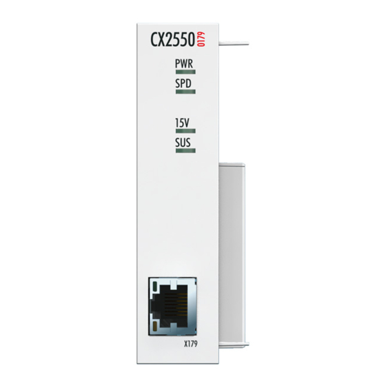
Page 19: Usb Connection
Mounting and wiring USB connection RJ 45 interface for CX2550-0179 (USB1.1) (X179): EtherCAT cable, category CAT5e. Table 1: Assignment of RJ 45 interface: Signal Description 15 V 15 V + Ground USB TX USB RX USB RX USB TX 15 V 15 V + Ground the LEDs of the RJ 45 sockets are redundantly implemented on the lower dagnostic LEDs [} 25]. -
Page 20: Commissioning / Configuration
Minimum requirements: 1. EtherCAT redundancy supplement 2. EK1110 (Bus extension) 3. EK1100 (Bus Coupler) The supplement product on the Beckhoff website at http://download.beckhoff.com/download/Software/TwinCAT/TwinCAT2/Supplement/ TwinCAT_EtherCAT_Redundancy/Install/TcEcRedundancy.exe can be downloaded. The required licence key can be ordered from our sales division. The required couplers are ordered together with the other hardware. - Page 21 This supplement only supports cable redundancy. This means that fail safety exists only for the cable sections. That means the connections between the couplers. Failures of individ- Note ual terminals are not covered.Further details can be found in the Beckhoff Information Sys- tem under EtherCAT cable redundancy. Cases of failure The two possible failures are described in the example below.
- Page 22 Commissioning / Configuration The interruption is indicated by "LNK_MIS B" and "LNK_MIS A". The next example shows a failure of the "return line": In this case the second cable is faulty. The terminals at the coupler continue to run without malfunction. The System Manager indicates the behaviour as follows: Version: 1.0 CX2550-0179 / CX2550-0279...
-
Page 23: Switching On And Off
Commissioning / Configuration The interruption is indicated by "LNK_MIS C" at coupler EK1100. The EtherCAT ring is expandable. The number of devices in the ring is controlled by licenses: up to 250, up to 1000, more than 1000. A master is only able to bridge one failure. In the event of two failures the ring components will continue to run up to the breaking points. -
Page 24: Cx2550-0179 - Architecture Description
USB hub to the USB device. Via the USB extension a Beckhoff Touch Panel can be connected. Thus a panel of type CP69xx/79xx can be operated up to 50 meters from the CX system without additional devices. -
Page 25: Error Handling And Diagnostics
Error handling and diagnostics Error handling and diagnostics LEDs Diagon the USB extension LEDs diagnosis for CX2550-0179 The following table shows the states for the LEDs of the CX2550-0179 (USB 1.1): Display Meaning Power supply The Power LED lights if the device is connected to a live power supply unit (green). -
Page 26: Faults
6. Any components / software used The quickest response will come from support / service in your country. Therefore please contact your regional contact. For details please refer to our website at www.beckhoff.de or ask your distribution partner. Version: 1.0... -
Page 27: Decommissioning
Decommissioning Decommissioning Disassembly and disposal The disassembly of a CX20x0 hardware configuration with system interfaces takes place in 3 steps 1. Switching off and disconnecting the power supply Before a CX20x0 system can be dismantled, the system should be switched off, and the power supply should be disconnected. - Page 28 Subsequently, the system interfaces can be separated again. Do not use force to open the device! Opening the module housing by force would destroy it. The devices may only be opened by Beckhoff service personnel. Attention Version: 1.0...
-
Page 29: Appendix
All products of the Embedded PC family are CE, UL and GOST-R certified. Since the product family is continuously developed further, we are unable to provide a full listing here. The current list of certified products can be found at www.beckhoff.com. FCC Approvals for the United States of America... -
Page 30: Support And Service
Beckhoff's branch offices and representatives Please contact your Beckhoff branch office or representative for local support and service on Beckhoff products! The addresses of Beckhoff's branch offices and representatives round the world can be found on her internet pages: http://www.beckhoff.com You will also find further documentation for Beckhoff components there.
Need help?
Do you have a question about the CX2550 Series and is the answer not in the manual?
Questions and answers