
Subscribe to Our Youtube Channel
Related Manuals for Beckhoff KL2502


Summary of Contents for Beckhoff KL2502
- Page 1 Documentation KL2502, KL2512 Dual Channel Pulse Width Output Terminals, 24 V DC Version: Date: 2019-10-11...
-
Page 3: Table Of Contents
Connection system ...................... 19 3.3.2 Wiring.......................... 21 3.3.3 Shielding .......................... 22 KL2502, KL2512 - Connection and LED description ............... 23 ATEX - Special conditions (standard temperature range) ............... 24 ATEX Documentation ........................ 25 4 Configuration Software KS2000 ...................... 26 KS2000 - Introduction ........................ 26 5 Access from the user program ...................... 28 Terminal configuration ........................ 28... - Page 4 Table of contents Version: 4.2 KL2502, KL2512...
-
Page 5: Foreword
EP1590927, EP1789857, EP1456722, EP2137893, DE102015105702 with corresponding applications or registrations in various other countries. ® EtherCAT is registered trademark and patented technology, licensed by Beckhoff Automation GmbH, Germany. Copyright © Beckhoff Automation GmbH & Co. KG, Germany. The reproduction, distribution and utilization of this document as well as the communication of its contents to others without express authorization are prohibited. -
Page 6: Safety Instructions
All the components are supplied in particular hardware and software configurations appropriate for the application. Modifications to hardware or software configurations other than those described in the documentation are not permitted, and nullify the liability of Beckhoff Automation GmbH & Co. KG. Personnel qualification This description is only intended for trained specialists in control, automation and drive engineering who are familiar with the applicable national standards. -
Page 7: Documentation Issue Status
02 - hardware version 02 Beckhoff Identification Code (BIC) The Beckhoff Identification Code (BIC) is increasingly being applied to Beckhoff products to uniquely identify the product. The BIC is represented as a Data Matrix Code (DMC, code scheme ECC200), the content is based on the ANSI standard MH10.8.2-2016. -
Page 8: Fig. 1 Bic As Data Matrix Code (Dmc, Code Scheme Ecc200)
The following information is contained: Item Type of Explanation Data Number of digits Example information identifier incl. data identifier Beckhoff order Beckhoff order number 1P 1P072222 number Beckhoff Traceability Unique serial number, SBTNk4p562d7 Number (BTN) see note below Article description Beckhoff article 1KEL1809 description, e.g. - Page 9 Example of composite information from item 1 to 4 and 6. The data identifiers are marked in red for better display: An important component of the BIC is the Beckhoff Traceability Number (BTN, item no. 2). The BTN is a unique serial number consisting of eight characters that will replace all other serial number systems at Beckhoff in the long term (e.g.
-
Page 10: Product Overview
Two-channel pulse width output terminal 24 V DC, positive switching The KL2502 output terminal modulates the pulse width of a binary signal, and outputs it electrically isolated from the K-bus. The mark/space ratio is prescribed by a 16 bit value from the automation device. The output stage is protected against overload and short-circuit. -
Page 11: Kl2512 - Introduction
KL2512. Via the fieldbus the output can be set independently for two channels with a resolution of more than 30,000 steps. The PWM frequency can be changed. The power transistors switch the ground connection and are electrically isolated from the internal K-bus. KL2502, KL2512 Version: 4.2... -
Page 12: Kl2502, Kl2512 - Technical Data
In the delivery state the KL2502 terminal occupies 6 bytes in the process image. The mapping of the KL2502 can be set by means of the controller or by the Bus Coupler's configuration interface using the Beckhoff KS2000 configuration software. -
Page 13: Operation Modes
Product overview Process data Input format: KL2502: Two's complement representation (integer -1 corresponds to 0xFFFF) The ratio of duty cycle/period is specified with a maximum resolution of 10 bit. KL2512: 16 bit unsigned integer Output value Process data KL2502 KL2512* 0 % Duty Cycle... - Page 14 Status bit 1 remains set as long as the output is active and status bit 2 returns the status of channel 1. Version: 4.2 KL2502, KL2512...
-
Page 15: Mounting And Wiring
• Each assembly must be terminated at the right hand end with a KL9010 bus end terminal, to ensure the protection class and ESD protection. Fig. 4: Spring contacts of the Beckhoff I/O components Installation on mounting rails WARNING... -
Page 16: Fig. 5 Attaching On Mounting Rail
To mount the mounting rails with a height of 7.5 mm under the terminals and couplers, you should use flat mounting connections (e.g. countersunk screws or blind rivets). Version: 4.2 KL2502, KL2512... -
Page 17: Fig. 6 Disassembling Of Terminal
EL91xx, EL92xx) interrupt the power contacts and thus represent the start of a new supply rail. PE power contact The power contact labeled PE can be used as a protective earth. For safety reasons this contact mates first when plugging together, and can ground short-circuit currents of up to 125 A. KL2502, KL2512 Version: 4.2... -
Page 18: Fig. 7 Power Contact On Left Side
Power Feed Terminals can be released and pulled at least 10 mm from the group of terminals. WARNING Risk of electric shock! The PE power contact must not be used for other potentials! Version: 4.2 KL2502, KL2512... -
Page 19: Connection
Insert the new component and plug in the connector with the wiring. This reduces the installation time and eliminates the risk of wires being mixed up. The familiar dimensions of the terminal only had to be changed slightly. The new connector adds about 3 mm. The maximum height of the terminal remains unchanged. KL2502, KL2512 Version: 4.2... -
Page 20: Fig. 10 High Density Terminals
Ultrasonically "bonded" (ultrasonically welded) conductors Ultrasonically “bonded" conductors It is also possible to connect the Standard and High Density Terminals with ultrasonically "bonded" (ultrasonically welded) conductors. In this case, please note the tables concerning the wire-size width below! Version: 4.2 KL2502, KL2512... -
Page 21: Wiring
The cables are released, as usual, using the contact release with the aid of a screwdriver. See the following table for the suitable wire size width. KL2502, KL2512 Version: 4.2... -
Page 22: Shielding
Wire size width (conductors with a wire end sleeve) 0.14 ... 0.75 mm Wire size width (ultrasonically “bonded" conductors) only 1.5 mm Wire stripping length 8 ... 9 mm 3.3.3 Shielding Shielding Encoder, analog sensors and actors should always be connected with shielded, twisted paired wires. Version: 4.2 KL2502, KL2512... -
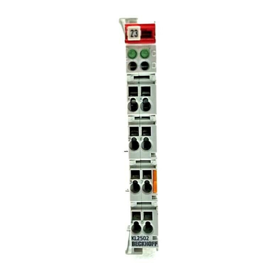
Page 23: Kl2502, Kl2512 - Connection And Led Description
Mounting and wiring KL2502, KL2512 - Connection and LED description WARNING Risk of injury through electric shock and damage to the device! Bring the Bus Terminal system into a safe, voltage-free state before starting mounting, disassembly or wiring of the Bus Terminals! Fig. 12: KL2502, KL2512 - Connection and LEDs... -
Page 24: Atex - Special Conditions (Standard Temperature Range)
80°C at the wire branching points, then cables must be selected whose tempera- ture data correspond to the actual measured temperature values! • Observe the permissible ambient temperature range of 0 to 55°C for the use of Beckhoff fieldbus compo- nents standard temperature range in potentially explosive areas! •... -
Page 25: Atex Documentation
Notes about operation of the Beckhoff terminal systems in potentially explosive ar- eas (ATEX) Pay also attention to the continuative documentation Notes about operation of the Beckhoff terminal systems in potentially explosive areas (ATEX) that is available in the download area of the Beckhoff homepage http:\\www.beckhoff.com! KL2502, KL2512... -
Page 26: Configuration Software Ks2000
Fieldbus Box modules with the aid of which settings can be modified easily. Alternatively, you have full access to all internal registers of the bus couplers and intelligent terminals. Refer to the register description for the meanings of the registers. Version: 4.2 KL2502, KL2512... - Page 27 • Process values can be specified in the output image for commissioning of the output modules. All possibilities in the online mode can be used in parallel with the actual fieldbus mode of the terminal station. The fieldbus protocol always has the higher priority in this case. KL2502, KL2512 Version: 4.2...
-
Page 28: Access From The User Program
Bus Coupler type and the set mapping configuration (e.g. Motorola/Intel format, word alignment etc.). In contrast to the analog input and output terminals, in the KL2502 the control byte and the status byte are always mapped, irrespective of the fieldbus system used. -
Page 29: Mapping In The Bus Coupler
If the terminals are fully evaluated, they occupy memory space in the input and output process image. The following tables provide information about how the terminals map themselves in the Bus Coupler, depending on the parameters set. The KL2502 is mapped with 6 bytes of input and output data. 5.2.1 KL2502... - Page 30 Channel n, data byte 1 (byte with the highest value) "-" This byte is not used or occupied by the terminal. Res. Reserved: this byte is assigned to the process data memory, although it has no function. Version: 4.2 KL2502, KL2512...
-
Page 31: Register Overview
0x0100 (256 SEEPROM R34 [} 34] Cycle duration PWM 0x0FA0 (4000 SEEPROM R35 [} 34] Duty cycle 0x4000 (16384 SEEPROM R36 [} 34] Pulse duration 0x0005 (5 SEEPROM R37 [} 34] R38…R63 Base frequency 2 (low word) 0x86A0 (34464 SEEPROM KL2502, KL2512 Version: 4.2... -
Page 32: Register Description
The particular byte contains the minimum data length for a channel that is to be transferred. If the MSB is set, the control and status byte is not necessarily required for the terminal function and is not transferred to the control, if the Bus Coupler is configured accordingly. Version: 4.2 KL2502, KL2512... - Page 33 If any other value is entered into this register, the write-protection is active. When write protection is not active, the code word is returned when the register is read. If the write protection is active, the register contains a zero value. KL2502, KL2512 Version: 4.2...
- Page 34 0x2000 corresponds to 25 % duty cycle 0x4000 corresponds to 50 % duty cycle. • R37: Pulse duration for Frq-Cnt pulse mode [0x0005] This register is used to enter the pulse duration in Frq-Cnt pulse mode. 1 digit corresponds to 8 µs. Version: 4.2 KL2502, KL2512...
-
Page 35: Control And Status Byte
: Access to register structure W/R = 0 : Read register W/R = 1 : Write register A5..A0 = register address Addresses A5...A0 can be used to address a total of 64 registers. Fig. 17: Register mode control byte KL2502, KL2512 Version: 4.2... -
Page 36: Examples Of Register Communication
• Bits 0.5 to 0.0 specify the register number 9 with 00 1001 • The output data word (byte 1 and byte 2) has no meaning during read access. To change a register, write the required value into the output word. Version: 4.2 KL2502, KL2512... -
Page 37: Example 2: Writing To An User Register
• The input data word (byte 1 and byte 2) is of no importance after the write access. Any values still displayed are invalid! II. Read Register 31 (check the set code word) Output Data Byte 0: Control byte Byte 1: DataOUT1, high byte Byte 2: DataOUT1, low byte 0x9F (1001 1111 0xXX 0xXX Explanation: KL2502, KL2512 Version: 4.2... - Page 38 IV. Read Register 32 (check changed feature register) Output Data Byte 0: Control byte Byte 1: DataOUT1, high byte Byte 2: DataOUT1, low byte 0xA0 (1010 0000 0xXX 0xXX Explanation: • Bit 0.7 set means: Register communication switched on. Version: 4.2 KL2502, KL2512...
- Page 39 • The terminal returns a value as a receipt in the status byte that differs only in bit 0.6 from the value of the control byte. • The input data word (byte 1 and byte 2) is of no importance after the write access. Any values still displayed are invalid! KL2502, KL2512 Version: 4.2...
-
Page 40: Appendix
Beckhoff's branch offices and representatives Please contact your Beckhoff branch office or representative for local support and service on Beckhoff products! The addresses of Beckhoff's branch offices and representatives round the world can be found on her internet pages: http://www.beckhoff.com You will also find further documentation for Beckhoff components there. - Page 41 KS2000 configuration software....................Fig. 14 Mapping in the Lightbus coupler – example for KL2502.............. Fig. 15 Mapping in the Profibus coupler – example for KL2502 .............. Fig. 16 Mapping in the Interbus coupler – example for KL2502 .............. Fig. 17 Register mode control byte......................
Need help?
Do you have a question about the KL2502 and is the answer not in the manual?
Questions and answers