
Subscribe to Our Youtube Channel
Related Manuals for Beckhoff KM10 2 Series


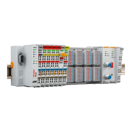
Summary of Contents for Beckhoff KM10 2 Series
- Page 1 Documentation | EN KM10x2, KM10x4, KM10x8 Terminal Modules with Digital Inputs 2022-09-12 | Version: 3.2.0...
-
Page 3: Table Of Contents
Table of contents Table of contents 1 Foreword .............................. 5 Notes on the documentation ...................... 5 Safety instructions .......................... 6 Documentation issue status ...................... 7 2 Product overview ............................ 8 Terminal Modules - System Overview .................... 8 KM1002, KM1012 ........................... 11 2.2.1 Introduction ........................ - Page 4 Table of contents Version: 3.2.0 KM10x2, KM10x4, KM10x8...
-
Page 5: Foreword
, XTS and XPlanar are registered trademarks of and licensed by Beckhoff Automation GmbH. Other designations used in this publication may be trademarks whose use by third parties for their own purposes could violate the rights of the owners. Patent Pending... -
Page 6: Safety Instructions
All the components are supplied in particular hardware and software configurations appropriate for the application. Modifications to hardware or software configurations other than those described in the documentation are not permitted, and nullify the liability of Beckhoff Automation GmbH & Co. KG. Personnel qualification This description is only intended for trained specialists in control, automation and drive engineering who are familiar with the applicable national standards. -
Page 7: Documentation Issue Status
Foreword Documentation issue status Version Comment 3.2.0 • Chapter “Technical data” updated • Document structure updated • Chapter “Disposal” added • New title page • Revision status updated 3.1.0 • Technical data for KM plug connectors updated 3.0.0 • Migration •... -
Page 8: Product Overview
Terminal reliably meets increased requirements for I/O signals through its modularity and compact design. The existing Beckhoff Bus Terminal system is complemented by the new version of the EMxxxx / KMxxxx Terminal Module with increased packing density. In many areas of application, cost benefits can be realized through lower overall installed size and application-specific signal mix. -
Page 9: Fig. 2 Pluggable Connection (Fixed Wiring)
Product overview Fig. 2: Pluggable connection (fixed wiring) Connection Plug connectors are available for single and triple conductor connection methods. Fig. 3: Terminal module with plug connector for single conductor connection method (ZS2001-0002) Fig. 4: Terminal module with plug connector for triple-conductor connection method (ZS2001-0004) KM10x2, KM10x4, KM10x8 Version: 3.2.0... -
Page 10: Fig. 5 Terminal Module With 16 Channels
Product overview Packing density The Terminal Modules combine 16, 32 or 64 digital inputs or outputs on a very small area. This compact and slimline design enables very high packing densities, leading to smaller control cabinets and terminal boxes. Fig. 5: Terminal module with 16 channels Fig. 6: Terminal module with 32 channels Version: 3.2.0 KM10x2, KM10x4, KM10x8... -
Page 11: Km1002, Km1012
Product overview Fig. 7: Terminal module with 64 channels KM1002, KM1012 2.2.1 Introduction Fig. 8: KM10x2-0002, KM10x2-0004 KM10x2, KM10x4, KM10x8 Version: 3.2.0... -
Page 12: Technical Data
The control signals are transmitted (electrically isolated) to the higher-level automation device. Like the standard Bus Terminals, the terminal modules are integrated in the Beckhoff I/O system. Plug connectors with spring connections enable permanent wiring and are optionally available with 1 or 3 pins. -
Page 13: Km1004, Km1014
The control signals are transmitted (electrically isolated) to the higher-level automation device. Like the standard Bus Terminals, the terminal modules are integrated in the Beckhoff I/O system. Plug connectors with spring connections enable permanent wiring and are optionally available with 1 or 3 pins. -
Page 14: Technical Data
Product overview See also section Ordering information for KM connectors [} 16]. 2.3.2 Technical data Technical data KM1004 KM1014 Number of inputs 32 (4 x 8) Rated voltage 24 V (-15%/+20%) Signal voltage “0” -3 V ... 5 V Signal voltage “1” 15 V ... 30 V Input filter 3.0 ms 0.2 ms Input current typically 5 mA Power supply for the electronics... -
Page 15: Km1008, Km1018
The control signals are transmitted (electrically isolated) to the higher-level automation device. Like the standard Bus Terminals, the terminal modules are integrated in the Beckhoff I/O system. Plug connectors with spring connections enable permanent wiring and are optionally available with 1 or 3 pins. -
Page 16: Technical Data
Product overview 2.4.2 Technical data Technical data KM1008 KM1018 Number of inputs 64 (8 x 8) Rated voltage 24 V (-15%/+20%) Signal voltage “0” -3 V ... 5 V Signal voltage “1” 15 V ... 30 V Input filter 3.0 ms 0.2 ms Input current typically 5 mA Power supply for the electronics via the K-Bus Current consumption from K-bus typically 3 mA... -
Page 17: Fig. 12 Km Plug-In Connector For Tree-Wire Connection (Zs2001-0004)
Product overview Fig. 12: KM plug-in connector for tree-wire connection (ZS2001-0004) Ordering name Signal LEDs Wiring technique single-wire two-wire three-wire ZS2001-0001 ZS2001-0002 ZS2001-0004 2.5.2 Technical Data Technical Data ZS2001-0001 ZS2001-0002 ZS2001-0004 Number of terminal points Signal LEDs Nominal voltage 24 V Nominal current 2 A Cycle of connector operation Wire size width... -
Page 18: Mounting And Wiring
Mounting and wiring Mounting and wiring Recommended mounting rails Terminal Modules und EtherCAT Modules of KMxxxx and EMxxxx series, same as the terminals of the EL66xx and EL67xx series can be snapped onto the following recommended mounting rails: • DIN Rail TH 35-7.5 with 1 mm material thickness (according to EN 60715) •... -
Page 19: Fig. 14 Dimensions Km10X4, Km20X4
Mounting and wiring KM10x4, KM20x4 Fig. 14: Dimensions KM10x4, KM20x4 KM10x8, KM20x8 Fig. 15: Dimensions KM10x8, KM20x8 Width of a Bus Terminal block NOTE Pay attention to the maximum with and the current consumption A maximum of 64 Bus Terminals or Bus Terminal Modules may be aligned to a Bus Coupler! An overall with of 80 cm must not be exceeded! Also take care that the current consumption of the Bus Terminals / Bus Terminal Modules does not overstrain the K-Bus power supply of the Bus Coupler! KM10x2, KM10x4, KM10x8... -
Page 20: Mounting And Demounting - Terminals With Traction Lever Unlocking
Mounting and wiring Mounting and demounting - terminals with traction lever unlocking The terminal modules are fastened to the assembly surface with the aid of a 35 mm mounting rail (e.g. mounting rail TH 35-15). Fixing of mounting rails The locking mechanism of the terminals and couplers extends to the profile of the mounting rail. At the installation, the locking mechanism of the components must not come into conflict with the fixing bolts of the mounting rail. - Page 21 Mounting and wiring • In the case 32 and 64 channel terminal modules (KMxxx4 and KMxxx8 or EMxxx4 and EMxxx8) you now lever the second unlatching hook on the right-hand side of the terminal module upwards in the same way. •...
-
Page 22: Mounting And Demounting - Terminals With Front Unlocking
Mounting and wiring Mounting and demounting - terminals with front unlocking The terminal modules are fastened to the assembly surface with the aid of a 35 mm mounting rail (e.g. mounting rail TH 35-15). Fixing of mounting rails The locking mechanism of the terminals and couplers extends to the profile of the mounting rail. At the installation, the locking mechanism of the components must not come into conflict with the fixing bolts of the mounting rail. -
Page 23: Disposal
Mounting and wiring • Pull (4) the terminal module away from the mounting surface. Avoid canting of the module; you should stabilize the module with the other hand, if required. Disposal Products marked with a crossed-out wheeled bin shall not be discarded with the normal waste stream. -
Page 24: Wiring
Mounting and wiring Wiring WARNING Risk of electric shock and damage of device! Bring the bus terminal system into a safe, powered down state before starting installation, disassembly or wiring of the Bus Terminals! Supply voltage connection The illustration shows the connection of the supply voltage for the module electronics and the actuators to two KM connectors. - Page 25 Mounting and wiring Connecting the actuators Pin assignment for channels 1 to 16 Channel Terminal point at KM connector For terminal modules with more than 16 channels, you will find the assignment of the channels to the additional KM connectors in the description of the Process image. KM10x2, KM10x4, KM10x8 Version: 3.2.0...
-
Page 26: Connection Technology
Mounting and wiring Connection technology The sensors can be connected in • single-conductor (see example, terminal point 0), • two-conductor (see example, terminal point 3), or • three-conductor mode (see example, terminal point 6) Fig. 17: Connection Version: 3.2.0 KM10x2, KM10x4, KM10x8... -
Page 27: Access From The User Program
Access from the user program Access from the user program Process image KM1002, KM1012 The process image of the KM1002/KM1012 terminal modules consists of 2 bytes of input data. Byte offset Format Input data KM connector Byte DataIN (channel 1 to 8) Byte DataIN (channel 9 to 16) KM1004, KM1014... -
Page 28: Appendix
Please contact your Beckhoff branch office or representative for local support and service on Beckhoff products! The addresses of Beckhoff's branch offices and representatives round the world can be found on her internet pages: https://www.beckhoff.com You will also find further documentation for Beckhoff components there. - Page 29 Table of figures Table of figures Fig. 1 Bus Terminal Block ........................Fig. 2 Pluggable connection (fixed wiring) ..................... Fig. 3 Terminal module with plug connector for single conductor connection method (ZS2001-0002) . Fig. 4 Terminal module with plug connector for triple-conductor connection method (ZS2001-0004)... Fig.
- Page 31 More Information: www.beckhoff.com/KM1xxx Beckhoff Automation GmbH & Co. KG Hülshorstweg 20 33415 Verl Germany Phone: +49 5246 9630 info@beckhoff.com www.beckhoff.com...
Need help?
Do you have a question about the KM10 2 Series and is the answer not in the manual?
Questions and answers