
Subscribe to Our Youtube Channel
Related Manuals for Beckhoff KM2002


Summary of Contents for Beckhoff KM2002
- Page 1 Documentation KM2002, KM2004, KM2008 Terminal modules with digital outputs, 24 V, 0.5 A Version: 3.2.0 Date: 2017-01-23...
-
Page 3: Table Of Contents
Table of contents 1 Foreword .............................. 4 Notes on the documentation...................... 4 Safety instructions .......................... 5 Documentation Issue Status...................... 6 2 Product overview............................ 7 Terminal Modules - System Overview .................... 7 KM2002 ............................ 10 2.2.1 Introduction ........................ 10 2.2.2 Technical data........................ 11 KM2004 ............................ 12 2.3.1 Introduction ........................ 12... -
Page 4: Foreword
The TwinCAT Technology is covered, including but not limited to the following patent applications and patents: EP0851348, US6167425 with corresponding applications or registrations in various other countries. ® EtherCAT is registered trademark and patented technology, licensed by Beckhoff Automation GmbH, Germany Copyright © Beckhoff Automation GmbH & Co. KG, Germany. -
Page 5: Safety Instructions
All the components are supplied in particular hardware and software configurations appropriate for the application. Modifications to hardware or software configurations other than those described in the documentation are not permitted, and nullify the liability of Beckhoff Automation GmbH & Co. KG. Personnel qualification This description is only intended for trained specialists in control, automation and drive engineering who are familiar with the applicable national standards. -
Page 6: Documentation Issue Status
• Notes about wiring technique corrected • Technical data updated 1.0.0 • KM2004 and KM2008 added • Mounting and demounting added • Dimension drawings added • first preliminary documentation for KM2002 Firm and hardware versions Documentation Hardware version version KM2002... -
Page 7: Product Overview
Terminal reliably meets increased requirements for I/O signals through its modularity and compact design. The existing Beckhoff Bus Terminal system is complemented by the new version of the EMxxxx / KMxxxx Terminal Module with increased packing density. In many areas of application, cost benefits can be realized through lower overall installed size and application-specific signal mix. -
Page 8: Fig. 3 Terminal Module With Plug Connector For Single Conductor Connection Method (Zs2001-0002)
The Terminal Modules combine 16, 32 or 64 digital inputs or outputs on a very small area. This compact and slimline design enables very high packing densities, leading to smaller control cabinets and terminal boxes. Version: 3.2.0 KM2002, KM2004, KM2008... -
Page 9: Fig. 5 Terminal Module With 16 Channels
Product overview Fig. 5: Terminal module with 16 channels Fig. 6: Terminal module with 32 channels Fig. 7: Terminal module with 64 channels KM2002, KM2004, KM2008 Version: 3.2.0... -
Page 10: Introduction
Digital Terminal Module with 16 output channels (24 V The terminal module KM2002 combines 16 digital outputs with 8 channels per plug connector in a compact design with high packing density. The binary control signals are transferred (electrically isolated) to the actuators at the process level. -
Page 11: Technical Data
Current consumption from the load voltage (24 V) typically 15 mA With of an Bus Terminal block max. [} 18] 64 standard bus terminals or 80 cm (for this a KM2002 is equivalent to 2 standard bus terminals) Electrical isolation 500 V (K-Bus / signal voltage) Bit width in the output process image 16 bit... -
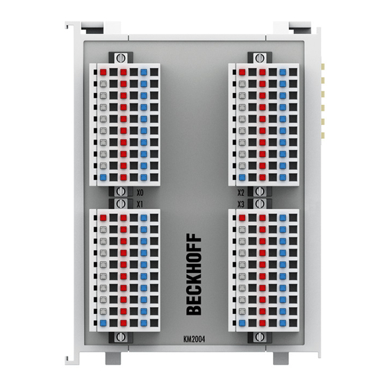
Page 12: Introduction
Like the standard Bus Terminals, the terminal modules are integrated in the Beckhoff I/O system. Plug connectors with spring connections enable plug-in wiring and are available with 1 or 3 pins. LEDs integrated in the connector indicate the signal state for each channel directly at the wire. The outputs are protected against overload and short circuit. -
Page 13: Technical Data
35 mm mounting rail according to EN 60715 Mounting [} 19] Vibration / shock resistance conforms to EN 60068-2-6 / EN 60068-2-27 EMC resistance burst / ESD conforms to EN 61000-6-2 / EN 61000-6-4 Protection class IP20 Installation position variable Approval KM2002, KM2004, KM2008 Version: 3.2.0... -
Page 14: Fig. 10 Digital Terminal Modules With 64 Output Channels
64 channels (0.5 A), with 8 connectors ZS2001-0001 KM2008-0002 digital output module, 64 channels (0.5 A), with 8 connectors ZS2001-0002 KM2008-0004 digital output module, 64 channels (0.5 A), with 8 connectors ZS2001-0004 See also chapter ordering information for KM plug-in connectors [} 15]. Version: 3.2.0 KM2002, KM2004, KM2008... -
Page 15: Km Plug-In Connectors
EMC resistance burst / ESD conforms to EN 61000-6-2 / EN 61000-6-4 Protection class IP20 Installation position variable Approval KM plug-in connectors 2.5.1 Ordering information for KM plug-in connector Fig. 11: KM plug-in connector for single-wire connection (ZS2001-0001, ZS2001-0002) KM2002, KM2004, KM2008 Version: 3.2.0... -
Page 16: Fig. 12 Km Plug-In Connector For Tree-Wire Connection (Zs2001-0004)
-25°C ... +55°C range during storage Permissible relative humidity 80%, no condensation Vibration / shock resistance conforms to EN 60068-2-6 / EN 60068-2-27 EMC resistance burst / ESD conforms to EN 61000-6-2 / EN 61000-6-4 Protection class IP20 Installation position variable Version: 3.2.0 KM2002, KM2004, KM2008... -
Page 17: Mounting And Wiring
Terminal Modules und EtherCAT Modules of KMxxxx and EMxxxx series, same as the ter- minals of the EL66xx and EL67xx series does not fit to the DIN Rail TH 35-15 with 2,2 to Note 2,5 mm material thickness (according to EN 60715)! Dimensions KM10x2, KM20x2 Fig. 13: Dimensions KM10x2, KM20x2 KM2002, KM2004, KM2008 Version: 3.2.0... -
Page 18: Fig. 14 Dimensions Km10X4, Km20X4
An overall with of 80 cm must not be exceeded! Also take care that the current con- Attention sumption of the Bus Terminals / Bus Terminal Modules does not overstrain the K-Bus power supply of the Bus Coupler! Version: 3.2.0 KM2002, KM2004, KM2008... -
Page 19: Mounting And Demounting - Terminals With Traction Lever Unlocking
• Lever the unlatching hook on the left-hand side of the terminal module upwards with a screwdriver (3). As you do this ◦ an internal mechanism pulls the two latching lugs (3a) from the top hat rail back into the terminal module, ◦ the unlatching hook moves forwards (3b) and engages KM2002, KM2004, KM2008 Version: 3.2.0... - Page 20 • In the case 32 and 64 channel terminal modules (KMxxx4 and KMxxx8 or EMxxx4 and EMxxx8) you now lever the second unlatching hook on the right-hand side of the terminal module upwards in the same way. • Pull (4) the terminal module away from the mounting surface. Version: 3.2.0 KM2002, KM2004, KM2008...
-
Page 21: Mounting And Demounting - Terminals With Front Unlocking
• Remove all the cables. • Lever the unlatching hook back with thumb and forefinger (3). An internal mechanism pulls the two latching lugs (3a) from the top hat rail back into the terminal module. KM2002, KM2004, KM2008 Version: 3.2.0... - Page 22 Mounting and Wiring • Pull (4) the terminal module away from the mounting surface. Avoid canting of the module; you should stabilize the module with the other hand, if required. Version: 3.2.0 KM2002, KM2004, KM2008...
-
Page 23: Wiring
The illustration shows the connection of the supply voltage for the module electronics and the actuators to two KM connectors. Fig. 16: Supply voltage connection Power the internal electronics • the positive supply voltage to terminal location +24 V • the negative supply voltage to terminal location 0 V Note KM2002, KM2004, KM2008 Version: 3.2.0... - Page 24 Channel Terminal point at KM connector For terminal modules with more than 16 channels, you will find the assignment of the channels to the additional KM connectors in the description of the Process image [} 26]. Version: 3.2.0 KM2002, KM2004, KM2008...
-
Page 25: Connection
Mounting and Wiring Connection The actuators can be connected in • single- (see example, terminal point 0), • two- (see example, terminal point 3) or • three wire technique (see example, terminal point 6). Fig. 17: Connection KM2002, KM2004, KM2008 Version: 3.2.0... -
Page 26: Access From The User Programm
Access from the user programm Access from the user programm Process Image KM2002 The process image of the terminal module KM2002 consists of 2 byte output data. Byte offset Format Output data KM plug-in connector byte DataOUT (channel 1 to 8) -
Page 27: Appendix
Beckhoff's branch offices and representatives Please contact your Beckhoff branch office or representative for local support and service on Beckhoff products! The addresses of Beckhoff's branch offices and representatives round the world can be found on her internet pages: http://www.beckhoff.com You will also find further documentation for Beckhoff components there. - Page 28 KM plug-in connector for single-wire connection (ZS2001-0001, ZS2001-0002) ......Fig. 12 KM plug-in connector for tree-wire connection (ZS2001-0004) ........... Fig. 13 Dimensions KM10x2, KM20x2..................... Fig. 14 Dimensions KM10x4, KM20x4..................... Fig. 15 Dimensions KM10x8, KM20x8..................... Fig. 16 Supply voltage connection......................Fig. 17 Connection........................... Version: 3.2.0 KM2002, KM2004, KM2008...
Need help?
Do you have a question about the KM2002 and is the answer not in the manual?
Questions and answers