Beckhoff KL85 Series Documentation

Beckhoff KL85 Series Documentation

Manual operating modules with k-bus interface
Table of Contents

Advertisement

Quick Links

Documentation
KL85xx und KL9309
Manual operating modules with K-Bus interface
Version:
Date:
2.1.0
2018-02-27

Advertisement

Table of Contents
loading

Summary of Contents for Beckhoff KL85 Series

  • Page 1 Documentation KL85xx und KL9309 Manual operating modules with K-Bus interface Version: 2.1.0 Date: 2018-02-27...
  • Page 3: Table Of Contents

    Table of contents Table of contents 1 Foreword .............................. 5 Notes on the documentation...................... 5 Safety instructions ..........................  6 Documentation Issue Status...................... 7 2 Product overview............................ 9 Introduction .............................  9 KL8500 ............................ 10 2.2.1 KL8500 – Introduction ...................... 10 2.2.2 Technical data........................ 11 KL8519 ............................ 12 2.3.1 KL8519 - Introduction....................... 12 2.3.2...
  • Page 4 Table of contents Data types.............................  55 4.3.1 E_KL8519_KBusOffReact .................... 56 4.3.2 ST_KL8519InData ...................... 56 4.3.3 ST_KL8519OutData...................... 56 4.3.4 ST_KL8524InData ...................... 57 4.3.5 ST_KL8524OutData...................... 57 4.3.6 ST_KL8528InData ...................... 57 4.3.7 ST_KL8528OutData...................... 58 4.3.8 ST_KL8548InData ...................... 58 4.3.9 ST_KL8548OutData...................... 58 Error codes ...........................  59 Adjustment of the LED displays.................... 59 4.5.1 Standard function LED KL8519 .................. 59 4.5.2 Standard function LED KL8524 .................. 59...
  • Page 5: Foreword

    The TwinCAT Technology is covered, including but not limited to the following patent applications and patents: EP0851348, US6167425 with corresponding applications or registrations in various other countries. ® EtherCAT is registered trademark and patented technology, licensed by Beckhoff Automation GmbH, Germany Copyright © Beckhoff Automation GmbH & Co. KG, Germany.
  • Page 6: Safety Instructions

    All the components are supplied in particular hardware and software configurations appropriate for the application. Modifications to hardware or software configurations other than those described in the documentation are not permitted, and nullify the liability of Beckhoff Automation GmbH & Co. KG. Personnel qualification This description is only intended for trained specialists in control, automation and drive engineering who are familiar with the applicable national standards.
  • Page 7: Documentation Issue Status

    Foreword Documentation Issue Status Version Comment 2.1.0 • Chapter Technical data for KL8548 updated 2.0.0 • Migration • Chapter Function blocks extended • Chapter Adjustment of LED displays added 1.5.0 • Description for disabling manual operation via the PLC program added •...
  • Page 8 Foreword 33 - week of production 33 06 - year of production 2006 B1 - firmware version B1 00 - hardware version 00 Version: 2.1.0 KL85xx und KL9309...
  • Page 9: Product Overview

    Product overview Product overview Introduction Fig. 1: Manual operating module with K-bus interface Manual operating modules with K-bus interface The manual operating modules have been developed for the switching, controlling and observation of digital and analog signals. They enable the setting and reading of data and values in case of failure of a controller. The manual operating modules provide the functionality of a local priority control/display unit according to EN ISO 16484-2:2004, Chapter 5.4.3.
  • Page 10: Kl8500 - Introduction

    Older TwinCAT versions may also be able to support the manual operating modules, if a current bus terminal configuration file (TcTerminals) is used. The current bus terminal configuration file is available from the Beckhoff website under Download/Configuration files/Bus Terminals. KL8500 2.2.1...
  • Page 11: Technical Data

    Product overview 2.2.2 Technical data Technical data KL8500 Number of inputs/outputs Bus interface I/O connection Diagnostic LEDs none Electrical isolation Power consumption Us Output process image Input process image Weight approx. 90 g Dimensions (W x H x D) 71 mm x 127.5 mm x 75 mm (external dimensions; see Mounting [} 26] for installation dimensions) Mounting Installation in the control cabinet door...
  • Page 12: Kl8519 - Introduction

    Product overview KL8519 2.3.1 KL8519 - Introduction Fig. 3: KL8519 16-channel digital input signal module The KL8519 is a 16-channel digital input signal module. 16 digital inputs can be connected, which indicate their status via LEDs and transmit the data to the controller. The LEDs are bicolor LEDs in the colors red and green and can be parameterized individually to suit the needs of the plant.
  • Page 13: Technical Data

    Product overview 2.3.2 Technical data Technical data KL8519 Number of inputs Input filter 3.0 ms Rated voltage 24 V (-15 %/+20 %) Bus interface K-bus connection IN/OUT I/O connection Ribbon cable connection, 20-pin Diagnostic LEDs bicolor LEDs green/red Electrical isolation 500 V (K-bus) Power consumption Us typically 50 mA Output process image...
  • Page 14: Kl8524 - Introduction

    Product overview KL8524 2.4.1 KL8524 - Introduction Fig. 4: KL8524 4 x 2-channel digital output module The KL8524 is a 4 x 2-channel digital output module, equipped with two switches. The first is for switching between manual and automatic operation, while the second is used to set a 2-stage output. It is possible to specify when and how the two outputs are switched.
  • Page 15: Technical Data

    Product overview 2.4.2 Technical data Technical data KL8524 Number of outputs 2 x 4 Output current 0.5 A (total current 2 A) Rated voltage 24 V (-15 %/+20 %) Bus interface K-bus connection IN/OUT I/O connection Ribbon cable connection, 20-pin Diagnostic LEDs bicolor LEDs green/yellow Switch settings 4 x auto/manual;...
  • Page 16: Kl8528 - Introduction

    Product overview KL8528 2.5.1 KL8528 - Introduction Fig. 5: KL8528 8-channel digital output module The KL8528 is an 8-channel digital output module. The outputs can be switched via a switch or specified by the controller. The status is indicated by a bicolor LED in green and yellow. The switching positions are readable via the PLC.
  • Page 17: Technical Data

    Product overview 2.5.2 Technical data Technical data KL8528 Number of outputs Output current 0.5 A (total current 2 A) Rated voltage 24 V (-15 %/+20 %) Bus interface K-bus connection IN/OUT I/O connection Ribbon cable connection, 20-pin Diagnostic LEDs bicolor LEDs green/yellow Switch settings 8 x auto/off/on Electrical isolation 500 V (K-bus)
  • Page 18: Kl8548 - Introduction

    Product overview KL8548 2.6.1 KL8548 - Introduction
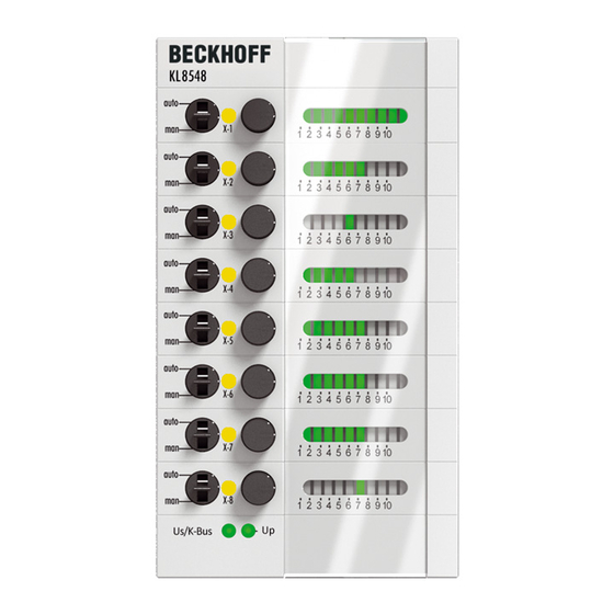
 Fig. 6: KL8548 8-channel analog output module 0…10 V The KL8548 is an 8-channel analog output module for 0…10 V. The analog values must be specified individually for each channel via the controller or via a potentiometer. The actual output value is indicated by a bar graph.
  • Page 19: Technical Data

    Product overview 2.6.2 Technical data Technical data KL8548 Number of inputs 8 (potentiometer) Number of outputs Signal voltage 0...10 V Load > 5 kΩ (short circuit proof) Accuracy ± 0.5 LSB linearity error, ± 0.5 LSB offset error Output error < ± 0.1 % (relative to full scale value) A/D converter 12 bit Rated voltage 24 V...
  • Page 20: Kl9020: End Terminal With K-Bus Extension

    The Bus Coupler carries out all diagnosis and commissioning tasks. Documentation for the K-bus extension Further information may be found in the documentation for K-Bus Extension (KL9020/ KL9050), that is available at the download area of the Beckhoff homepage. Note Version: 2.1.0...
  • Page 21: Technical Data

    Product overview 2.7.2 Technical data Technical data KL9020 Fieldbus independent Number of KL9020 per Fieldbus Coupler Connection for K-bus extension RJ-45 socket Current consumption from the K-bus typically 70 mA Configuration automatic Dielectric strength 500 V (shielding, base plate / K-bus) Weight approx.
  • Page 22: Kl9309 - Introduction

    Product overview KL9309 2.8.1 KL9309 - Introduction Fig. 8: KL9309 Adapter terminal for manual operating modules The KL9309 adapter terminal has 16 terminal points, which provide the I/Os of the KL85xx manual operating modules. An additional supply voltage (24 V ) is provided via two terminal points (24 V, 0 V). The terminal can be connected to the manual operating module via a system cable using a 20-pole pin contact strip with locking.
  • Page 23: Technical Data

    Product overview 2.8.2 Technical data Technical data KL9309 Power supply 24 V Power contacts max. 24 V  / max. 10 A Rated voltage Up 24 V , total current max. 2 A Bus interface K-bus passive (no process image in the K-bus), counts as two K-bus terminals I/O connection Ribbon cable connection, 20-pin, 16-way HD connection...
  • Page 24: Fig. 10 Leds

    Product overview Rear side Fig. 10: LEDs Meaning of the LED displays Color State and significance green Lit, either weakly or strongly: K-bus communication OK No K-Bus communication No K-Bus communication No error Version: 2.1.0 KL85xx und KL9309...
  • Page 25: Mounting And Wiring

    Mounting and wiring Mounting and wiring Dimensions Fig. 11: Dimensions Mounting cut-out and connector The mounting cut-out [} 26] should have a size of 67 mm x 116.2 mm. Make sure that there is sufficient space behind the module for the connectors. Note KL85xx und KL9309 Version: 2.1.0...
  • Page 26: Mounting Cut-Out

    Mounting and wiring Mounting cut-out The mounting cut-out should have a size of 67 mm x 116.2 mm. Fig. 12: Mounting cut-out Positioning depends on the wall thickness of the mounting surface The figure shows that different mounting heights arise depending on the wall thickness when installing in the mounting surface.
  • Page 27: Installation On Mounting Rails

    Mounting and wiring Installation on mounting rails Risk of electric shock and damage of device! Bring the bus terminal system into a safe, powered down state before starting installation, disassembly or wiring of the Bus Terminals! WARNING Assembly Fig. 13: Attaching on mounting rail The Bus Coupler and Bus Terminals are attached to commercially available 35 mm mounting rails (DIN rails according to EN 60715) by applying slight pressure: 1.
  • Page 28: Fig. 14 Disassembling Of Terminal

    Mounting and wiring Disassembly Fig. 14: Disassembling of terminal Each terminal is secured by a lock on the mounting rail, which must be released for disassembly: 1. Pull the terminal by its orange-colored lugs approximately 1 cm away from the mounting rail. In doing so for this terminal the mounting rail lock is released automatically and you can pull the terminal out of the bus terminal block easily without excessive force.
  • Page 29: Connecting The Manual Operating Modules

    Mounting and wiring Fig. 15: Power contact on left side Possible damage of the device Note that, for reasons of electromagnetic compatibility, the PE contacts are capacitatively coupled to the mounting rail. This may lead to incorrect results during insulation testing or Attention to damage on the terminal (e.g.
  • Page 30: Fig. 17 Function Switch

    Mounting and wiring Mounting When mounting, observe the information in the chapter entitled Mounting rail installation [} 27]. 1. Ensure that the system is powered down and in a safe state. 2. Install the first bus terminal block, consisting of the fieldbus coupler and the desired Bus Terminals, on a mounting rail.
  • Page 31 Mounting and wiring 3. Carefully pull the orange-colored strap approximately 1 cm out of the terminal to be disassembled, un- til it protrudes loosely. The lock with the mounting rail is now released for this terminal, and the termi- nal can be pulled from the mounting rail without excessive force. 4.
  • Page 32: Power Supply

    Mounting and wiring Power supply Risk of injury through electric shock and damage to the device! Bring the Bus Terminal system into a safe, voltage-free state before starting mounting, dis- assembly or wiring of the Bus Terminals! WARNING Link the ground connections of the power supply units of the Bus Coupler and all manual operating modules with a low-resistance connection For interference-proof operation of the K-bus extension, the ground of the K-bus power Attention...
  • Page 33: Connection Diagrams Of The 20-Pin Connectors

    Mounting and wiring Connection diagrams of the 20-pin connectors KL8519 Connection diagram for the 20-pin connector on the rear side of the KL8519. Fig. 19: KL8519 - Connecting the 20-pin connector KL8524 Connection diagram for the 20-pin connector on the rear side of the KL8524. Fig. 20: KL8524 - Connecting the 20-pin connector KL8528 Connection diagram for the 20-pin connector on the rear side of the KL8528.
  • Page 34: Fig. 21 Kl8528 - Connecting The 20-Pin Connector

    Mounting and wiring Fig. 21: KL8528 - Connecting the 20-pin connector KL8548 Connection diagram for the 20-pin connector on the rear side of the KL8548. Fig. 22: KL8548 - Connecting the 20-pin connector KL9309 Connection diagram of the 20-pin connector at the front of the KL9309. Version: 2.1.0 KL85xx und KL9309...
  • Page 35: Labelling

    Labelling This documentation contains a Word file with templates for the labelling of the control cabinet modules: https://infosys.beckhoff.com/content/1033/kl85xx/Resources/zip/3913381387.zip Make sure when printing that your printer does not scale the page size, so that the label strips retain their original size.
  • Page 36 Mounting and wiring Sensor/actuator cable from KL85xx to KL9303 Order designation Description ZK8500-8282-7030 PVC cable, 20 x 0.14 mm², plug connector at both ends for KL85xx, KL9309 and terminals with ribbon cable connection, length 3 m, shielded ZK8500-8282-7040 PVC cable, 20 x 0.14 mm², plug connector at both ends for KL85xx, KL9309 and terminals with ribbon cable connection, length 4 m, shielded ZK8500-8282-7050 PVC cable, 20 x 0.14 mm², plug connector at both ends for KL85xx, KL9309 and...
  • Page 37: Programming In Twincat

    Note Download for CX9000 (https://infosys.beckhoff.com/content/1033/kl85xx/Resources/ zip/3913383563.zip) Required libraries: • Standard.lib • TcKL85xx.lib Download for BX9000 (serial) (https://infosys.beckhoff.com/content/1033/kl85xx/Resources/ zip/3913385739.zip) Required libraries: • Standard.lbx • TcKL85xx.lbx Download for BC9000 (serial) (https://infosys.beckhoff.com/content/1033/kl85xx/Resources/ zip/3913387915.zip) Required libraries: •...
  • Page 38: Twincat 3

    Programming in TwinCAT Download for BC9050 (serial) (https://infosys.beckhoff.com/content/1033/kl85xx/Resources/ zip/3913390091.zip) Required libraries: • Standard.lbx • TcKL85xx.lbx 4.1.2 TwinCAT 3 Installation From TwinCAT 3.1.4020.14 the "Tc2_KL85xx" libraries are installed by default. Note Function blocks Overview Function block Description Function block for the configuration of the KL8519, for reading out the FB_KL8519 [} 39]...
  • Page 39: Kl8519

    Programming in TwinCAT 4.2.1 KL8519 Function blocks Description Function block for the configuration of the KL8519, for reading out the digital signals FB_KL8519 [} 39] and for setting the LEDs. 4.2.1.1 FB_KL8519 Fig. 24: Function block FB_KL8519 Application This function block is used to configure the KL8519 [} 12], to read out the digital signals and to set the LEDs. The function block must be called once per cycle.
  • Page 40 Programming in TwinCAT bExecCfg: The configurations wDisCh, wSetCol, wInv, wBiCol and eKBusOff are written to the terminals when a positive edge is detected. bBusy goes TRUE. Note that the inputs are not updated during this time. wDisCh: Configuration: Disablement of the standard function [} 59]of the LEDs. The LEDs can be set by the PLC.
  • Page 41: Kl8524

    Programming in TwinCAT 4.2.2 KL8524 Function blocks Description Function block for the configuration of the KL8524, for reading out the digital signals FB_KL8524 [} 41] and for setting the outputs/LEDs. 4.2.2.1 FB_KL8524 Fig. 25: Function block FB_KL8524 Application This function block is used to configure the KL8524 [} 14], to read out the digital signals and to set the outputs/LEDs.
  • Page 42 Programming in TwinCAT byDisCh: Configuration: Disablement of the standard function [} 59]of the LEDs. The LEDs can be set by the PLC. Bit 0 = LED 1, ... , bit 7 = LED 8. 255 ) deactivates the standard function [} 59] of all LEDs. These can then be set from the PLC via byLEDGn or byLEDYe.
  • Page 43: Fig. 26 Function Block Fb_Kl8524Ex

    Programming in TwinCAT byStatOut: Status of the digital output signals. Bit 0 = channel 1 output 1, bit 1 = channel 1 output 2, ... , bit 7 = channel 4 output 2. The FB_KL85xxByteTo8Bit [} 54] function block is available for preparing the signals for the graphic programming languages. bErr: The bError output goes TRUE as soon as an error occurs.
  • Page 44 Programming in TwinCAT byTurnOnDelayCh4    : BYTE; byOut               : BYTE; byLEDGn             : BYTE; byLEDYe             : BYTE; bDisManMode         : BOOL; dwOpt               : DWORD := 0; bEn: The function block is enabled by setting bEn to TRUE in the PLC program. With bEn = FALSE the execution of the function block will be stopped and all outputs reset. bExecCfg: The configurations byDisCh, byKBusOff, byOutMode, byTurnOnDelayCh1, byTurnOnDelayCh2, byTurnOnDelayCh3 and byTurnOnDelayCh4 are written to the terminals.
  • Page 45: Kl8528

    Programming in TwinCAT bBusy: bBusy is TRUE as long as the configuration is being written (start with bExecCfg). Note that the inputs are not updated during this time. byStatSwiAuto: Status of the "auto" switch. Bit 0 = channel 1, ... , bit 3 = channel 4. The FB_KL85xxByteTo8Bit function block is available for preparing the signals for the graphic programming languages.
  • Page 46 Programming in TwinCAT The variable byDisCh switches the standard function [} 60] of the LEDs off. The LEDs can now be switched independently of the digital input signal via the PLC with the variables byLEDGn or byLEDYe. Each LED can be changed individually here. The respective output can be set to "TRUE"...
  • Page 47: Fig. 28 Function Block Fb_Kl8528Ex

    Programming in TwinCAT bErr: The bError output goes TRUE as soon as an error occurs. This error is described via the udiErrID variable. udiErrID: In the event of an error the output issues an error code (see error codes [} 59]). bError goes TRUE at the same time.
  • Page 48 Programming in TwinCAT byDisCh: Configuration: Disablement of the standard function of the LEDs. The LEDs can be set by the PLC. Bit 0 = LED 1, ... , bit 7 = LED 8. 255 ) deactivates the standard function of all LEDs. These can then be set from the PLC via byLEDGn or byLEDYe.
  • Page 49: Kl8548

    Programming in TwinCAT 4.2.4 KL8548 Function blocks Description Function block for configuration of the KL8548, for reading out the digital signals and FB_KL8548 [} 49] for setting the outputs/LEDs. 4.2.4.1 FB_KL8548 Fig. 29: Function block FB_KL8548 Application This function block is used to configure the KL8548 [} 18], to read out the digital signals and to set the outputs/LEDs.
  • Page 50: Fig. 30 Function Block Fb_Kl8548Ex

    Programming in TwinCAT dwOpt: For future options. VAR_OUTPUT bBusy         : BOOL; bStaSwiAuto   : BOOL; wStaPoti      : WORD; wStaOut       : WORD; bErr          : BOOL; udiErrID      : UDINT; bBusy: bBusy is TRUE as long as the configuration is being written (start with bExecCfg). Note that the inputs are not updated during this time. bStaSwiAuto: Status of the switch. TRUE = "auto" FALSE = "man". wStaPoti: Status of the potentiometer.
  • Page 51 Programming in TwinCAT VAR_INPUT bEn             : BOOL; bExecCfg        : BOOL; bDisWatchdog    : BOOL; bEnEcoMode      : BOOL; bEnPwrOnVal     : BOOL; wPwrOnVal       : WORD; wOut            : WORD; bDisManMode     : BOOL; dwOpt           : DWORD; bEn: The function block is enabled by setting bEn to TRUE in the PLC program. With bEn = FALSE the execution of the function block will be stopped and all outputs reset. bExecCfg: The configurations bDisWatchdog, bEnEcoMode, bEnPwrOnVal and wPwrOnVal are written to the terminals when a positive edge is encountered.
  • Page 52: Kl85Xx - Helper

    Programming in TwinCAT VAR_IN_OUT stInData      : ST_KL8548InData; stOutData     : ST_KL8548OutData; stInData: Process image of the inputs (see ST_KL8548InData). stOutData: Process image of the outputs (see ST_KL8548OutData). 4.2.5 KL85xx - Helper Function blocks Description Conversion from 16 bits to 1 Word FB_KL85xx16BitToWord [} 52] Conversion from 8 bits to 1 byte FB_KL85xx8BitToByte [} 53] Conversion from 1 byte to 8 bits.
  • Page 53: Fig. 32 Function Block Fb_Kl85Xx8Bittobyte

    Programming in TwinCAT b05: Bit 4 b06: Bit 5 b07: Bit 6 b08: Bit 7 b09: Bit 8 b10: Bit 9 b11: Bit 10 b12: Bit 11 b13: Bit 12 b14: Bit 13 b15: Bit 14 b16: Bit 15 VAR_OUTPUT wOut      : WORD; wOut: Word composed of the 16 bits. 4.2.5.2 FB_KL85xx8BitToByte Fig. 32: Function block FB_KL85xx8BitToByte Application This function block converts 8 bits to 1 byte. VAR_INPUT b01    : BOOL; b02    : BOOL; b03    : BOOL;...
  • Page 54: Fig. 33 Function Block Fb_Kl85Xxbyteto8Bit

    Programming in TwinCAT 4.2.5.3 FB_KL85xxByteTo8Bit Fig. 33: Function block FB_KL85xxByteTo8Bit Application This function block converts 1 byte to 8 bits. VAR_INPUT byIn      : BYTE; byIn: Byte to be broken down into 8 bits. VAR_OUTPUT b01       : BOOL; b02       : BOOL; b03       : BOOL; b04       : BOOL; b05       : BOOL; b06       : BOOL; b07       : BOOL; b08       : BOOL; b01: Bit 0 b02: Bit 1 b03: Bit 2 b04: Bit 3 b05: Bit 4 b06: Bit 5 b07: Bit 6...
  • Page 55: Data Types

    Programming in TwinCAT Application This function block converts 1 word to 16 bits. VAR_INPUT wIn      : WORD; wIn: Word to be broken down into 16 bits. VAR_OUTPUT b01      : BOOL; b02      : BOOL; b03      : BOOL; b04      : BOOL; b05      : BOOL; b06      : BOOL; b07      : BOOL; b08      : BOOL; b09      : BOOL; b10      : BOOL; b11      : BOOL; b12      : BOOL; b13      : BOOL; b14      : BOOL; b15      : BOOL; b16      : BOOL; b01: Bit 0 b02: Bit 1 b03: Bit 2 b04: Bit 3 b05: Bit 4...
  • Page 56: E_Kl8519_Kbusoffreact

    Programming in TwinCAT Data type Description Reaction of the LEDs of the KL8519 in the event of a E_KL8519_KBusOffReact [} 56] K-bus error 4.3.1 E_KL8519_KBusOffReact Reaction of the LEDs of the KL8519 in the event of a K-bus error. These LEDs must have been activated via "wDisCh".
  • Page 57: St_Kl8524Indata

    Programming in TwinCAT byLEDoutRed_1: Data byte 3: red LED 1 to 8 (must be enabled via wDisCh) byLEDoutRed_2: Data byte 4: red LED 9 to 16 (must be enabled via wDisCh) 4.3.4 ST_KL8524InData Process image of the inputs for the KL8524 Linked to the terminals in the System Manager. TYPE ST_KL8524InData : STRUCT   byState       : BYTE;...
  • Page 58: St_Kl8528Outdata

    Programming in TwinCAT byState: Status byte byAutoManual: Data byte 1: Switch position "auto" for output 1 to 8 (the output is set via the PLC) byOnOff: Data byte 2: Switch position "on" for output 1 to 8 (the output is set independently of the PLC) 4.3.7 ST_KL8528OutData Process image of the outputs for the KL8528...
  • Page 59: Error Codes

    Programming in TwinCAT wDataOut: Data word 1: sets the output value via the PLC if the respective switch is set to "auto". (0x0000=0V, 0x3FFF=+5V, 0x7FFF=+10V) Error codes Value Value Description (hex) (dec) 0x0000 No error 0x8001 32769 Watchdog Error. The terminal does not respond. This message usually means that there is no connection to the terminal.
  • Page 60: Standard Function Led Kl8528

    Programming in TwinCAT The LEDs flash green if the automatic switch is set to "man" and the respective output is TRUE (set by the three-step switch). This functionality can be disabled with the variable byDisCh. The LEDs can then be set from the PLC. 4.5.3 Standard function LED KL8528 The LEDs light up steadily yellow if the switch is set to auto and the output is FALSE.
  • Page 61 Programming in TwinCAT The display mode can be selected separately for each analog value by writing to register R32.4 [} 86] or with the function blocks FB_KL8548 [} 49] or FB_KL8548Ex [} 50]. KL85xx und KL9309 Version: 2.1.0...
  • Page 62: Data Structures Of The Modules

    Data structures of the modules Data structures of the modules KL8519 5.1.1 KL8519 – Process image The KL8519 is represented in the process image with 6 bytes each of input and output data. These are organized as follows: Byte offset Format Input data Output data Byte...
  • Page 63 Data structures of the modules Register communication Control byte 1 in register communication Control byte 1 (CB1) is located in the output image [} 62], and is transmitted from the controller to the terminal. CB1.7 CB1.6 CB1.5 CB1.4 CB1.3 CB1.2 CB1.1 CB1.0 Name RegAccess Reg.
  • Page 64: Kl8519 - Register Overview

    Data structures of the modules 5.1.3 KL8519 – Register overview The registers are used for the parameterization of the Bus Terminals and are available for each channel. They can be read or written by means of the register communication [} 63]. Register no.
  • Page 65 Data structures of the modules • Register R63: 0x0000 R8: Terminal description The name of the terminal is contained in register R8. KL8519: 0 x 2147 (8519 R9: Firmware version Register R9 contains the ASCII coding of the terminal's firmware version, e.g. 0x3141 = '1A'. The '0x31' corresponds here to the ASCII character '1', while the '0x41' represents the ASCII character 'A'.
  • Page 66 Data structures of the modules R33.15 R33.14 R33.13 R33.12 R33.11 R33.10 R33.9 R33.8 Name colLED_Ch16 colLED_Ch1 colLED_Ch1 colLED_Ch13 colLED_Ch12 colLED_Ch11 colLED_Ch10 colLED_Ch9 R33.7 R33.6 R33.5 R33.4 R33.3 R33.2 R33.1 R33.0 Name colLED_Ch8 colLED_Ch7 colLED_Ch6 colLED_Ch5 colLED_Ch4 colLED_Ch3 colLED_Ch2 colLED_Ch1 Name Description default R33.15...
  • Page 67: Kl8524 - Process Image

    Data structures of the modules Name Description default R35.15 invLED_Ch16 The LED of input 16 lights up green if the input is inactive (0 The LED of input 16 lights up red if the input is active (1 R35.14 invLED_Ch15 The LED of input 15 lights up green if the input is inactive (0 The LED of input 15 lights up red if the input is active (1 R35.0...
  • Page 68 Data structures of the modules Control and status byte See chapter Control and status byte [} 70] Process data Input data Data byte 1 Data byte 1 indicates the positions of the switches auto/man. Name Description enAutoC1 auto/man switch of channel 1 is set to man: the three-step switch controls this channel.
  • Page 69 Data structures of the modules Name Description stateC1.1 Output C1.1 is not set Output C1.1 is set stateC1.2 Output C1.2 is not set Output C1.2 is set stateC4.2 Output C4.1 is not set Output C4.1 is set stateC4.2 Output C4.2 is not set Output C4.2 is set Output data Data byte 1...
  • Page 70: Kl8524 - Control And Status Bytes

    Data structures of the modules Name Description LED C1.1 LED K1.1 lights up yellow yellow LED C1.2 LED K1.2 lights up yellow yellow LED C4.1 LED K4.1 lights up yellow yellow LED C4.2 LED K4.2 lights up yellow yellow 5.2.2 KL8524 - control and status bytes Channel 1 Process data mode...
  • Page 71 Data structures of the modules Name Description CB1.7 RegAccess 1 Register communication switched on CB1.6 Read access Write access CB1.5 to CB1.0 Reg. no. Register number: Enter the number of the register that you - want to read with input data word DataIN1 [} 67] or - want to write with output data word DataOUT1 [} 67].
  • Page 72: Kl8524 - Register Overview

    Data structures of the modules 5.2.3 KL8524 – Register overview The registers are used for the parameterization of the Bus Terminals and are available for each channel. They can be read or written by means of the register communication [} 70]. Register no.
  • Page 73: Kl8524 - Register Description

    Data structures of the modules 5.2.4 KL8524 – Register description The registers are used for the parameterization of the Bus Terminals and are available for each channel. They can be read or written by means of the register communication. R7: Command register To execute a standard command, the user code word 0x1235 must be entered in register R31 [} 73].
  • Page 74 Data structures of the modules R32.7 R32.6 R32.5 R32.4 R32.3 R32.2 R32.1 R32.0 Name enSetLED_Ch4 enSetLED_Ch3 enSetLED_Ch2 enSetLED_Ch1 Name Description default R32.15 reserved R32.4 reserved R32.3 enSetLED_Ch4 LEDs of channel 4 cannot be set by the PLC LEDs of channel 4 can be set by the PLC R32.0 enSetLED_Ch1 LEDs of channel 1 cannot be set by the PLC...
  • Page 75 Data structures of the modules Name Description default R37.15 reserved R37.9 reserved R37.8 OutputMode (ar- Channel 1 is operated in output mode 1 Mode) Channel 1 is operated in output mode 2 R37.7- TurnOnDelay No switch-on delay R37.0 10 ms switch-on delay 20 ms switch-on delay 2550 ms switch-on delay ) OutputMode (arMode): Output mode 1:...
  • Page 76: Kl8528 - Process Image

    Data structures of the modules • switch position 1 to switch position 2 • Fast switching from 0 to 2 always takes place via switch position 1 and therefore also starts the delay time. Examples: • Output 1 switches on immediately when the three-stage switch is switched from 0 to 1. •...
  • Page 77 Data structures of the modules Process data Input data Data byte 1 Data byte 1 indicates the positions of the switches (auto/man). Name Description enAutoCh1 Switch of channel 1 is set to auto: the PLC controls this channel. enAutoCh2 Switch of channel 2 is set to auto: the PLC controls this channel. enAutoCh8 Switch of channel 8 is set to auto: the PLC controls this channel.
  • Page 78: Kl8528 - Control And Status Bytes

    Data structures of the modules Name Description LED 1 green LED 1 lights up yellow LED 2 green LED 2 lights up yellow LED 8 green LED 8 lights up yellow 5.3.2 KL8528 - control and status bytes Channel 1 Process data mode Control byte 1 in process data mode Control byte 1 (CB1) is located in the output image [} 76], and is transmitted from the controller to the...
  • Page 79 Data structures of the modules Name Description CB1.7 RegAccess Register communication switched on CB1.6 Read access Write access CB1.5 to CB1.0 Reg. no. Register number: Enter the number of the register that you - want to read with input data word DataIN1 [} 76] or - want to write with output data word DataOUT1 [} 76].
  • Page 80: Kl8528 - Register Overview

    Data structures of the modules 5.3.3 KL8528 – Register overview The registers are used for the parameterization of the Bus Terminals and are available for each channel. They can be read or written by means of the register communication [} 78]. Register no.
  • Page 81 Data structures of the modules R9: Firmware version Register R9 contains the ASCII coding of the terminal's firmware version, e.g. 0x3141 = '1A'. The '0x31' corresponds here to the ASCII character '1', while the '0x41' represents the ASCII character 'A'. This value cannot be changed. R12: Minimum data length of a channel R16: Hardware version number Register R16 contains the hardware version of the terminal.
  • Page 82: Kl8548 - Process Image

    Data structures of the modules Name Description default R33.15 reserved R33.8 reserved R33.7 K-bus-OFF-Reac- In the event of a K-bus error output 8 is reset (0 tion_Ch8 In event of a K-bus error output 8 is set (1 R33.6 K-Bus-OFF-Reac- In the event of a K-bus error output 7 is reset (0 tion_Ch7 In event of a K-bus error output 7 is set (1 R33.0...
  • Page 83: Kl8548 - Control And Status Bytes

    Data structures of the modules Process data Input data (DataIN1 to DataIN8) Position of the potentiometers with user scaling switched off (R32.0 [} 81] = 0) Potentiometer Input value in the PLC position hexadecimal decimal CCW stop 0x0000 Center 0x3FFF 16383 CW stop 0x7FFF 32767...
  • Page 84 Data structures of the modules Name Description SB1.7 RegAccess Acknowledgment for process data mode SB1.6 - SB1.1 reserved SB1.0 auto/man The auto/man switch of channel 1 is set to auto. The PLC controls the output. The auto/man switch of channel 1 is set to manual. The potentiometer controls the output.
  • Page 85: Kl8548 - Register Overview

    Data structures of the modules 5.4.3 KL8548 – Register overview Register Overview The registers are used for the parameterization of the Bus Terminals and are available for each channel. They can be read or written by means of the register communication [} 84]. Register no.
  • Page 86 Data structures of the modules R12: Minimum data length of a channel R16: Hardware version number Register R16 contains the hardware version of the terminal. R31: Code word register • If you write values into the user registers without first entering the user code word (0x1235) into the code word register, the terminal will not accept the supplied data.
  • Page 87: Examples Of Register Communication

    Data structures of the modules Examples of Register Communication The numbering of the bytes in the examples corresponds to the display without word alignment. 5.5.1 Example 1: reading the firmware version from Register 9 Output Data Byte 0: Control byte Byte 1: DataOUT1, high byte Byte 2: DataOUT1, low byte 0x89 (1000 1001...
  • Page 88 Data structures of the modules Input Data (answer of the bus terminal) Byte 0: Status byte Byte 1: DataIN1, high byte Byte 2: DataIN1, low byte 0x9F (1001 1111 0xXX 0xXX Explanation: • The terminal returns a value as a receipt in the status byte that differs only in bit 0.6 from the value of the control byte.
  • Page 89 Data structures of the modules Input data (response from the Bus Terminal) Byte 0: Status byte Byte 1: DataIN1, high byte Byte 2: DataIN1, low byte 0xA0 (1010 0000 0xXX 0xXX Explanation: • The terminal returns a value as a receipt in the status byte that differs only in bit 0.6 from the value of the control byte.
  • Page 90: Appendix

    Beckhoff's branch offices and representatives Please contact your Beckhoff branch office or representative for local support and service on Beckhoff products! The addresses of Beckhoff's branch offices and representatives round the world can be found on her internet pages: http://www.beckhoff.com You will also find further documentation for Beckhoff components there.
  • Page 91 List of illustrations List of illustrations Fig. 1 Manual operating module with K-bus interface................Fig. 2 KL8500 ............................Fig. 3 KL8519 ............................Fig. 4 KL8524 ............................Fig. 5 KL8528 ............................Fig. 6 KL8548 ............................Fig. 7 KL9020 ............................Fig. 8 KL9309 ............................

This manual is also suitable for:

Kl8528Kl9309Kl8548Kl8500Kl9020Kl8519 ... Show all

Table of Contents