Table of Contents
Advertisement
Advertisement
Table of Contents

Subscribe to Our Youtube Channel
Related Manuals for Xylem FLYGT SmartRun SRC 311


Summary of Contents for Xylem FLYGT SmartRun SRC 311
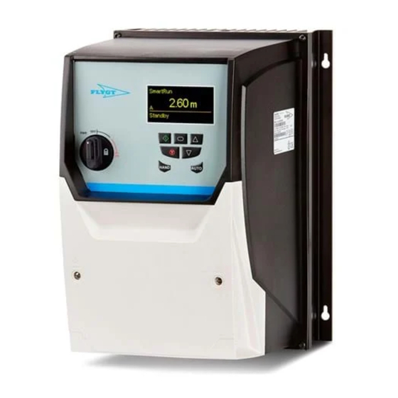
- Page 1 User guide ™ SRC 311 - SmartRun...
-
Page 3: Table Of Contents
Table of Contents Table of Contents Introduction and Safety.........................2 SRC 311..............................2 Electromagnetic Compatibility......................3 Important Safety Information......................3 Installation...............................6 Mechanical Installation........................6 Dimensions............................6 Torque values for installation......................7 Mounting clearance..........................8 Removing the Terminal Cover......................9 Electrical Installation.........................10 Grounding the Drive........................10 Wiring Precautions.........................11 Incoming Power Connection......................11 Drive and Motor Connection......................12 Motor Terminal Box Connections....................12 Control Terminal Wiring........................12... -
Page 4: Introduction And Safety
Introduction and Safety Introduction and Safety SRC 311 Frame Size 2 - 3 Frame Sizes 4 - 6 L2/N L1/N L1 L2 L3 1. Mechanical mounting, see Mechanical Installation (page 6). 2. Display (Status, Diagnostics, and Programming). 3. Keypad Operations see Display and buttons (page 15). -
Page 5: Electromagnetic Compatibility
Introduction and Safety Electromagnetic Compatibility All SRC 311 are designed with high standards of EMC in mind. All versions suitable for operation on 1–phase 230-V and 3–phase 400-V supplies, and intended for use within the European Union, are fitted with an internal EMC filter. This EMC filter is designed to reduce the conducted emissions back into the supply via the power cables for compliance with harmonized European standards. - Page 6 Introduction and Safety This variable speed drive product is intended for professional incorporation into complete equipment or systems as part of a fixed installation. If installed incorrectly it may present a safety hazard. The SRC 311 uses high voltages and currents, carries a high level of stored electrical energy, and is used to control mechanical plant that may cause injury.
- Page 7 Introduction and Safety Within the European Union, all machinery in which this product is used must comply with Directive 98/37/EC, Safety of Machinery. In particular, the machine manufacturer is responsible for providing a main switch and ensuring the electrical equipment complies with EN60204-1.
-
Page 8: Installation
Installation Installation Mechanical Installation General • The SRC 311 must be mounted in a vertical position only on a flat, flame-resistant vibration free mounting using the integral holes. • The SRC 311 must be installed in a pollution degree 1 or 2 environment only. •... -
Page 9: Torque Values For Installation
Installation Frame size C mm (in) 200.0 (7.87) 251.5 (9.90) D mm (in) 28.5 (1.12) 33.4 (1.31) E mm (in) 238.0 (9.37) 256.0 (10.08) F mm (in) 188.0 (7.40) 210.5 (8.29) G mm (in) 176.0 (6.93) 197.5 (7.78) H mm (in) 4.2 (0.17) 4.2 (0.17) I mm (in) -
Page 10: Mounting Clearance
Installation Screw Frame size Torque Nm (lbs-in) Power terminal 2 – 3 1 (8.85) 1.2 – 1.5 (10.6 – 13.2) 2.5 – 4.5 (22.5 – 39.8) 8 (70.8) Mounting clearance Minimum 200 mm (7.87 in) Minimum 10 mm (0.349 in) Typical drive heat losses are 3% of operating load conditions. -
Page 11: Removing The Terminal Cover
Installation Removing the Terminal Cover Frame Size 4 Frame Size 5 Using a suitable flat blade screwdriver, rotate the two Using a suitable flat blade screwdriver, rotate the four retaining screws indicated until the screw slot is vertical. retaining screws indicated until the screw slot is vertical. Terminal Cover Release Screws Frame Size 6 Remove the two screws indicated, lift the cover forwards and off. -
Page 12: Electrical Installation
Electrical Installation Grounding the Drive DANGER: This manual is intended as a guide for proper installation. Xylem Water Solution AB cannot assume responsibility for the compliance or the non-compliance to any code, national, local or otherwise, for the proper installation of this drive or associated equipment. -
Page 13: Wiring Precautions
Installation Shield Termination (Cable Screen) The safety ground terminal provides a grounding point for the motor cable shield. The motor cable shield connected to this terminal (drive end) should also be connected to the motor frame (motor end). Use a shield terminating or EMI clamp to connect the shield to the safety ground terminal. -
Page 14: Drive And Motor Connection
Installation Drive and Motor Connection • The motor should be connected to the SRC 311 U, V, and W terminals using a suitable 3 or 4 core cable. Where a 3 core cable is utilised, with the shield operating as an earth conductor, the shield must have a cross sectional area at least equal to the phase conductors when they are made from the same material. - Page 15 Installation Terminals Power terminal Unit 1 and 2 Control Terminal Unit 1 Control Terminal Unit 2 1 2 3 4 5 6 7 8 9 1011 12 13 1 2 3 4 5 6 7 8 9 10111213 1 2 3 4 5 6 Incoming power RFI-toroid core, for sizes 2 and 3...
- Page 16 Installation Terminal Type Function Outgoing power for the pump Table 2: Control I/O Terminal Type Function +24-V Output +24-V external supply is connected here for backup power Digital input 8-30V DC Pump block input Digital input 8-30V DC External alarm reset Digital input 8-30V DC Level switch + 10-V output (~20 mA Out)
-
Page 17: System Description
System Description System Description Display and buttons ON key is used to start the drive. Menu key is used to enter/exit (2 seconds) the menu and to confirm selection/change. Up key is used to increase a value or selection in the submenu. OFF key is used to turn off the drive. - Page 18 System Description Do not connect directly into an Ethernet port. The voltage destroys the Ethernet device. NOTICE: This RJ45 connector is not an Ethernet connection. Do not connect directly to an Ethernet port. Not used Not used Optibus - Optibus + +24 V, power supply for the remote key pad RS485- Modbus RTU/CanOpen RS485+ Modbus RTU/CanOpen...
-
Page 19: Technical Reference
Technical Reference Technical Reference Facility requirements Check that the following requirements are met: Environment The drive must be protected from direct sunlight and rainfall. Altitude Maximum altitude for non de-rated operation is 1000 m (3281 ft). De-rating above 1000 m (3281 ft) is 1% per 100 m (32.8 ft) of maximum nominal power. Maximum altitude with UL approval is 2000 m (6562 ft). -
Page 20: Maximum Supply Ratings For Ul- Compliance
Technical Reference Maximum supply ratings for UL- compliance The table describes the drivers suitable for a circuit capable of delivering specified maximum specified short-circuit Amperes symmetrical with the specified maximum supply voltage. Table 3: Drive ratings Voltage (V) Ratings kW (HP) Maximum supply voltage V Maximum supply short-circuit (AC) - Page 21 Technical Reference Frame Size Nominal Fuse/MCB, Supply cable Nominal 150% Output SUBCAB ® Input Current type B) (A) Output Current 60 cable (mm Current (A) seconds (A) 37.0 50.0 150.2 70.0 150.0 165.0 35.0 Table 7: 380 – 480 V (+ / -10%) 3–phase input, 3–phase output Frame Size Nominal Fuse/MCB,...
- Page 24 For more information on how Xylem can help you, go to xyleminc.com Xylem Water Solution AB Visit our Web site for the latest version of this document and more information Gesällvägen 33...
Need help?
Do you have a question about the FLYGT SmartRun SRC 311 and is the answer not in the manual?
Questions and answers