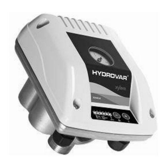
Xylem Hydrovar Instruction Manual
Speed control
Hide thumbs
Also See for Hydrovar:
- Instruction manual (80 pages) ,
- Installation, operation and maintenance manual (116 pages)
Advertisement
Hydrovar — Speed Control
SPEED CONTROL (ACTUATOR MODE) QUICK-START
GUIDE FOR FIFTH GENERATION HYDROVAR
The Hydrovar can be configured for speed control through an analog input. The controlling source can be an external
control device such as a PLC, BMS, (Building Management System) or potentiometer. For independently powered
signals, use AI2 on the X1 terminal.
1. For a 4-20 MA input signal, wire your 4-20MA signal
into X1 Terminal #5 and common on Terminal #6.
2. For a 0-10VDC input signal, wire your 0-10VDC signal
into X1 Terminal #5 and common on Terminal #6.
3. For a 0-20 MA input signal, wire your 0-20 MA signal
into X1 Terminal #5 and common on Terminal #6.
Input Signal
Positive Terminal
0-10 VDC
4-20 mA
0-20 mA
Negative Terminal
5
6
5
6
5
6
INSTRUCTION MANUAL
REMOVE COVER
IM297
Advertisement
Table of Contents

Summary of Contents for Xylem Hydrovar
- Page 1 SPEED CONTROL (ACTUATOR MODE) QUICK-START GUIDE FOR FIFTH GENERATION HYDROVAR The Hydrovar can be configured for speed control through an analog input. The controlling source can be an external control device such as a PLC, BMS, (Building Management System) or potentiometer. For independently powered signals, use AI2 on the X1 terminal.
- Page 2 To display your Speed Frequency select menu P02 ACTUATOR FREQUENCY Identify Terminal X1, AI2, Numbers 5 and 6 Xylem Inc. 2881 East Bayard Street Ext., Suite A, Seneca Falls, NY 13148 Phone: (866) 325-4210 Fax: (888) 322-5877 www.xyleminc.com © 2017 Xylem Inc. IM297 June 2017...


Need help?
Do you have a question about the Hydrovar and is the answer not in the manual?
Questions and answers