
Subscribe to Our Youtube Channel
Related Manuals for Xylem FLYGT SmartRun SRC 311


Summary of Contents for Xylem FLYGT SmartRun SRC 311
- Page 1 Installation, Operation, and Maintenance Manual ™ SRC 311 - SmartRun SRC311v.4.0IOMen-US...
- Page 3 Available languages Available languages Hrvatski Ovaj priručnik se može preuzeti i na hrvatskom jeziku sa http:// tpi.xyleminc.com. Český Tato příručka je také k dispozici ke stažení v českém jazyce na následující adrese: http://tpi.xyleminc.com. Dansk Denne vejledning kan også hentes på dansk fra http:// tpi.xyleminc.com.
- Page 5 Software version Software version This manual describes the features and functions of SRC 311, version 4.X. SRC 311 - SmartRun ™ Installation, Operation, and Maintenance Manual...
-
Page 7: Table Of Contents
Table of Contents Table of Contents Introduction and Safety........................3 Introduction..........................3 Safety.............................3 Safety terminology and symbols................... 3 User safety and health......................4 Product warranty......................... 4 Transportation and Storage......................6 Inspect the delivery........................6 Inspect the package........................ 6 Inspect the unit........................6 Transportation guidelines......................6 Lifting............................6 Storage guidelines........................ - Page 8 Table of Contents LED display messages, IP20....................34 Start-up guidelines........................34 Start and stop levels (default values)..................35 Change the language in the display..................36 Pump control functions......................36 Normal pump cycle.......................36 High inflow..........................36 Very high inflow........................37 Energy minimizer........................37 Alternation..........................38 Pump block..........................
-
Page 9: Introduction And Safety
Introduction and Safety Introduction and Safety Introduction CAUTION: • Read this manual carefully before installing and using the product. Improper use of the product can cause personal injury and damage to property, and may void the warranty. • Observe accident prevention regulations in force. •... -
Page 10: User Safety And Health
Xylem undertakes to remedy faults in products from Xylem under these conditions: • The fault is due to defects in design, materials, or workmanship. • The fault is reported to a Xylem representative within the warranty period. • The product is used only under the conditions described in this manual. - Page 11 However, should the need arise for a warranty claim, then contact your Xylem representative. Qualification of personnel All work on the product must be carried out by certified electricians or Xylem authorized mechanics. Xylem disclaims all responsibility for work done by untrained, unauthorized personnel.
-
Page 12: Transportation And Storage
Transportation and Storage Transportation and Storage Inspect the delivery Inspect the package 1. Inspect the package for damaged or missing items upon delivery. 2. Note any damaged or missing items on the receipt and freight bill. 3. File a claim with the shipping company if anything is out of order. If the product has been picked up at a distributor, make a claim directly to the distributor. - Page 13 Transportation and Storage Storage requirements The ambient temperature for the storage site must be between -40°C (-40°F) and 60°C (140°F). SRC 311 - SmartRun ™ Installation, Operation, and Maintenance Manual...
-
Page 14: Product Description
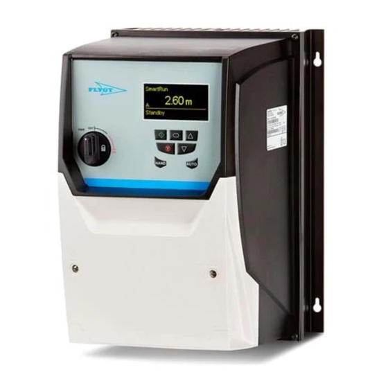
Product Description Product Description Product design ® The SRC 311 is a pump drive with the SmartRun functionality, which is dedicated for wastewater pump stations. The drive is one of the components that is included in the ® Experior system solution for pump stations. The system consists of a level sensor, a level switch, and the drives that controls and monitors the pumps in the pump station. -
Page 15: User Configurable Alarm Outputs
Product Description Indication Status Constant Flashing No communication Nothing No power User configurable alarm outputs Pin configuration WS007503 1. Relay 3 common 2. Relay 3 contact 3. Relay 4 common 4. Relay 4 contact 5. Relay 5 common 6. Relay 5 contact Specifications Data Description... -
Page 16: The Data Plate
Product Description Data Description Maximum switching current 6 A (250 V AC) / 5 A (30 V DC) Ambient temperature -10ºC – +50ºC International Protection Marking IP20 UL standard UL94V-0 Terminal torque value 0.5 Nm (4.5 Ib in) Communication The drive and the sump status and health can be monitored remotely. There are some parameters that are suitable for remote control. -
Page 17: Manual De-Rating
Product Description Model number SRC311-2-4-0040K-55 2 3 4 5 6 SmartRun ™ Control Product family Number of controlled pumps Generation Frame size (2–6) Input voltage 2:200 – 240V 4:380 – 480V 5:500 – 600V Power for example, 0040 = 4 Power unit K:Kilowatt H:Horsepower... -
Page 18: Mechanical Installation
Mechanical Installation Mechanical Installation Explosive zones WARNING: Do not use this unit in environments that may contain flammable/explosive or chemically aggressive gases or powders. Facility requirements This variable speed drive is intended for a professional incorporation into complete equipment or systems as part of a fixed installation. Close attention is required to system design and electrical installation. -
Page 19: Dimensions
Mechanical Installation • Ensure that the minimum mounting clearance is observed according to Mounting clearance (page 15). • Ensure that sufficient cooling is provided. 1. Drill four holes in the supporting wall. Dimensions (page 13). Do not carry out drilling operations with the drive in place. Dust and swarf from drilling may lead to damage. - Page 20 Mechanical Installation IP55 Frame size A mm (in) 450.0 (17.72) 540.0 (21.26) 865.0 (34.06) B mm (in) 428.0 (16.85) 515.0 (20.28) 830.0 (32.68) C mm (in) 433.0 (17.05) 520.0 (20.47) 840.0 (33.07) D mm (in) 8.0 (0.315) 8.0 (0.315) 10.0 (0.394) E mm (in) 252.0 (9.92) 270.0 (10.63)
-
Page 21: Mounting Clearance
Mechanical Installation Frame size D mm (in) 28.5 (1.12) 33.4 (1.31) E mm (in) 238.0 (9.37) 256.0 (10.08) F mm (in) 188.0 (7.40) 210.5 (8.29) G mm (in) 176.0 (6.93) 197.5 (7.78) H mm (in) 4.2 (0.17) 4.2 (0.17) I mm (in) 8.5 (0.33) 8.5 (0.33) Mounting clearance... -
Page 22: Install The Sensors
Mechanical Installation Frame size X mm (in) Y mm (in) 200 (7.9) 10 (0.394) 200 (7.9) 10 (0.394) 200 (7.9) 10 (0.394) IP66 Frame size X mm (in) Y mm (in) 150 (5.9) 10 (0.394) 150 (5.9) 10 (0.394) Typical drive heat losses are 3% of operating load conditions. NOTICE: The operating ambient temperature of the drive must be maintained. - Page 23 Mechanical Installation Level switch High level, ≤ 0.6 m (1.97 ft) above start level Start level Stop level Level sensor SRC 311 - SmartRun ™ Installation, Operation, and Maintenance Manual...
-
Page 24: Electrical Installation
Electrical Installation Electrical Installation Precautions Before starting work, make sure that the safety instructions in the chapter Introduction and Safety (page 3) have been read and understood. DANGER: Electrical Hazard Before starting work on the unit, make sure that the unit and the control panel are isolated from the power supply and cannot be energized. -
Page 25: Grounding Guidelines
Electrical Installation Requirements on fuses and circuit breakers • The fuses must comply with any local codes or regulations in place. In general, type gG (IEC 60269) or UL type T fuses are suitable; however in some cases type aR fuses is required. -
Page 26: Electromagnetic Compatibility
Electrical Installation Electromagnetic compatibility The installer must ensure that the equipment or system into which the product is incorporated complies with the Electromagnetic compatibility (EMC) legislation of the country of use. Within the European union, equipment into which this product is incorporated must comply with the EMC Directive 2004/108/EC. -
Page 27: Torque Values
Electrical Installation Torque values Control terminal Torque value 0.8 Nm (7.00 lb in) Power terminal Drive size lb in 8.85 8.85 3.00 15.0 11.10 20.0 15.00 Optional modules Torque value 0.5 Nm (4.50 lb in) Install the system Requirements • The mechanical installation of pumps, switch, and sensors is completed. •... - Page 28 Electrical Installation Condition Action If the drive is an IP55 version. Make sure that the cable glands are approved for IP55 environment. For frame size 4–6, use the enclosed metal plate to assemble the cable glands. If the drive is an IP66 version. Make sure that the cable glands are approved for IP66 environment. Drill two holes to install the cables in.
- Page 29 Electrical Installation L1/L L2/N L3 Figure 5: Frame size 2–3 Figure 6: Frame size 4–6 3. Connect a lead between the following terminals: The connections must be performed to get the drives to run. a) Connect terminals 1 and 12 on both drives. 2 3 4 5 6 7 8 9 10 11 2 3 4 5 6 7 8 9 10 11 13 14 15 16 17 18...
- Page 30 Electrical Installation c) If applicable, connect the ground (earth) to control terminal 7. d) Isolate and terminate T3 and T4 in an end-sleeve. 2 3 4 5 7 8 9 10 11 12 13 2 3 4 5 7 8 9 10 11 12 13 14 15 16 17 18 L1/L L2/N L3 Figure 11: Frame size 2–3 Figure 12: Frame size 4–6...
- Page 31 Electrical Installation 9 10 11 12 13 14 15 16 17 18 11 12 13 14 15 16 17 18 Figure 16: Frame size 4–6 1. Cable to enable shared sensor signals 2. Terminal 4 to terminal 4, shares the digital signal from the level switch 3.
-
Page 32: Terminals
Electrical Installation Terminals Power terminal Unit 1, 2 and 3 Control terminal Unit 1 Control Terminal Unit 2 T1 T2 T3 T4 T5 T6 T1 T2 T3 T4 T5 T6 T7 T8 T9 T10 T11 T12 T13 T1 T2 T3 T4 T5 T6 T7 T8 T9 T10 T11 T12 T13 10 11 10 11 Figure 19: Two pump system... - Page 33 Electrical Installation • EU: Gray • US: Red 16. Screen lead of the shared communication cable 17. Signal leads of the shared communication cable 18. Pump 2 19. Level sensor 20. Screen lead of the level sensor cable 21. Level sensor lead – 22.
-
Page 34: Install A Three Pump System
Electrical Installation Terminal Type Function Relay 3 contact, 250 V AC, 30 V DC, 5 A User configurable relay #3 Relay 4 common, 250 V AC, 30 V DC, 5 A User configurable relay #4 Relay 4 contact, 250 V AC, 30 V DC, 5 A User configurable relay #4 Relay 5 common, 250 V AC, 30 V DC, 5 A Relay #5 (Pump running output) -
Page 35: Install An Optional Module
Electrical Installation Use the screen lead/signal ground (earth) of the shared communication cable. c) Connect the level switch signal from drive 1. d) Connect terminal 4 on drive 2 to terminal 4 on drive 3. Control Terminal Unit 1 Relay Terminal Unit 1 Control Terminal Unit 3 Relay Terminal Unit 3 Control Terminal Unit 2... - Page 36 Electrical Installation Run signal VFD 1 Relay VFD 2 Relay VFD 3 Relay 14 15 16 17 18 14 15 16 17 18 14 15 16 17 18 SRC 311 - SmartRun ™ Installation, Operation, and Maintenance Manual...
-
Page 37: System Setup And Operation
System Setup and Operation System Setup and Operation Display and buttons IP20 IP55, IP66 Symbol Name Description The button is used to start the drive Navigate The button is used to enter/exit (2 seconds) the menu and to confirm selection/change (< 2 seconds). The button is used to increase a value or selection in the submenu. -
Page 38: Operating Mode
System Setup and Operation Operating mode Auto The drive controls the process using the current settings in the unit. The drive alternates between energy efficient operation and cleaning operations as prescribed by application conditions. Hand The operator controls the process manually using the display buttons. The pump does not use the level sensors in this mode and does not perform cleaning functions. - Page 39 System Setup and Operation Auto-Pump cleaning Auto-Sump cleaning 0.62 m 0.62 m 15.0 Hz 4.2 A 15 kW 15.0 Hz 4.2 A 15 kW Operating mode Auto/Manual Motor frequency Sump level Current Power Off mode The drive is powered on. All monitoring functions are active. No pump control functions are active and the pump does not run.
-
Page 40: Led Display Messages, Ip20
System Setup and Operation External block 0.62 m Inhibit LED display messages, IP20 This information do not apply to the IP55 and IP66 since they are equipped with OLED displays. Display Status Drive mains power is applied, but no Enable or Run signal is applied. -
Page 41: Start And Stop Levels (Default Values)
System Setup and Operation Open applicable parameter Action P1-16:Stop level Set the sump level where the pump stops pumping. The distance between the start level and the stop level must be <10% of the sensors measuring range. For example, a level sensor with the range 0-5 m (0-16.4 ft) must have the start level 0.5 m (0-1.64 ft) above the stop level. -
Page 42: Change The Language In The Display
System Setup and Operation The distance between the start level and the stop level must be <10% of the sensors measuring range. For example, a level sensor with the range 0-5 m (0-16.4 ft) must have the start level 0.5 m (0-1.64 ft) above the stop level. Change the language in the display 1. -
Page 43: Very High Inflow
System Setup and Operation Very high inflow The start level of pump 2 is low and the start level of pump 3 is high. If the inflow is very high, then pump 2 starts and increases the speed to the maximum frequency. Pump 1 starts to pump and increases the total outflow, when pump 2 reaches its maximum frequency. -
Page 44: Alternation
System Setup and Operation Specific energy (energy/pumped volume) Drive speed (Hz) Minimum speed limit, parameter P1-02:Minimum speed limit Optimal speed for this system Algorithm speed moving to optimum speed Maximum speed, parameter P1-01:Maximum speed limit To deactivate the Energy minimizer function and set a fixed optimal speed, set the P1-18:Energy frequency parameter to a negative speed. -
Page 45: Pump Block
System Setup and Operation For a two and three pump system the start distribution is 1:1 during normal inflow situations. During high inflow situations the start distribution is 5:5:2 for a three pump system, but remains 1:1 for a two pump system. P3 high 24 cm P2 high... -
Page 46: Cleaning
System Setup and Operation WS007551A Control Terminal Unit 1 Relay Terminal Unit Control Terminal Unit 2 Relay Terminal Unit 2 Relay Terminal Unit 3 Control Terminal Unit 3 10 11 12 13 14 15 16 17 18 10 11 12 13 10 11 12 13 14 15 16 17 18 14 15 16 17 18... -
Page 47: Maintenance Run
System Setup and Operation Start level Stop level Snore level Pipe cleaning Sump cleaning Pipe cleaning This function cleans the pipes by operating at the maximum frequency during one pump cycle. To avoid sedimentation and pipe clogging, the pump cleans the pipes by running the pump from the start level until the stop level is reached. -
Page 48: Optional Module Functions
System Setup and Operation Optional module functions External relay The P6-21:Relay output 3 and 4 parameter controls the function for relay 3 and 4. Relay 5 is always closed when the drive runs. External I/O controller To put the drive in external I/O control mode, close extended digital input 3. In external I/O control mode, the drive does not respond to the keypad buttons On, Off, Hand or Auto. - Page 49 System Setup and Operation 1. Set the drive in hand mode. 2. Press the On, Off, Up, and Down button at the same time until P-Def is shown in the display. 3. Press the Off button to confirm. The drive shows P-Def in the display when the parameter settings have been reset. SRC 311 - SmartRun ™...
-
Page 50: Maintenance
Maintenance Maintenance Ground continuity verification A ground (earth) continuity test must always be performed after service. Preventive maintenance Some of the product parts are subject to wear and have to be replaced with regular intervals to minimize untimely operation interruptions. Fans Internal IP55 and IP66 fans and external heat sink fans have to be replaced every three years. -
Page 51: Troubleshooting
Troubleshooting Troubleshooting Precautions Before starting work, make sure that the safety instructions in the chapter Introduction and Safety (page 3) have been read and understood. DANGER: Electrical Hazard Troubleshooting a live control panel exposes personnel to hazardous voltages. Electrical troubleshooting must be done by a qualified electrician. DANGER: Electrical Hazard Before starting work on the unit, make sure that the unit and the control panel are isolated from the power supply and cannot be energized. - Page 52 Troubleshooting Alarms are categorized as A- or B-alarms to differentiate between different priority levels with A-alarms being more serious than B-alarms. The relay contacts can be configured to output either A- or B-alarms. Table 8: Pump and process alarm Alarm Configurable Value Description Pump leakage...
-
Page 53: Reset Active Alarm
Troubleshooting sensor error and high level are active, the alarm code is sensor error alarm (8) + High-level alarm (4) + alarm active (16) = 28. If the alarm is reset, then the alarm code is reset to 0. Alarm display text Display text P1-19:Alarm state P0-50:Alarm log... - Page 54 Troubleshooting Display message Description of display messages Corrective action I.t-trp The drive has tripped on overload after • Increase acceleration rate or reduce the load. delivering >100% of value in • Make sure that the motor cable length is within the specified P1-08:Motor rated current for a time limit.
- Page 55 Troubleshooting Display message Description of display messages Corrective action U-dEF User parameter defaults Displayed when the Up, Down, and Stop buttons are pressed simultaneously. • Press the Off button to proceed. FAn-F Cooling fan fault Check and if necessary, replace the internal cooling fan. 0–hEAt Ambient temperature too high The measured temperature around the drive is above the operating...
- Page 56 Troubleshooting Display message Description of display messages Corrective action Sc-F03 Fitted communication module fault Internal communication to the inserted communications option module has been lost. • Check that the module is correctly inserted. Sc-F04 I/O card communications trip Internal communication to the inserted I/O option module has been lost.
-
Page 57: Technical Reference
Technical Reference Technical Reference System overview The drives share the functionality of the analog level sensor and the digital level sensor. The system does not have to use the same size of pump and drives; it is possible to use a mixture of pump and drive sizes. -
Page 58: Software Parameters
Technical Reference Software parameters Table 9: Changeable parameters Parameter name Default value Level Description P1-01:Maximum speed limit Varies Maximum speed limit P1-02:Minimum speed limit 30.0 Hz Minimum speed limit P1-03:Acceleration ramp time 1.0 s Acceleration ramp time P1-04:Deceleration ramp time 10.0 s Deceleration ramp time P1-06:Motor energy optimiser... - Page 59 Technical Reference Parameter name Default value Level Description P1-22:Leakage alarm setup Configure the leakage alarm. If no FLS is connected, then turn off the alarm. Setting FLS=Off will automatically configure the drive for the thermal contact triggering of the over temperature alarm. When over temperature alarm is active, hand-mode is not available.
- Page 60 Technical Reference Parameter name Default value Level Description P2-13:Analog output 2 function 0: Drive • 0: Drive running running • 1: Drive healthy • 2: At target speed • 3: Motor speed > 0 • 4: Speed >= limit • 5: Current >= limit •...
- Page 61 Technical Reference Parameter name Default value Level Description P4-18:Pump starts no Displays the number of pump starts. Reset the counter by writing zero to the parameter. P4-19:Snoring sensitivity Displays the amount of power that is consumed during snoring compared to the power consumed during normal operation that triggers a snoring event.
- Page 62 Technical Reference Parameter name Default value Level Description P6-21:Relay output 3 and 4 Configures when relay output is open or closed. One digit for each relay Relay 3: Position 1 Relay 4: Position 2 • 0: Enable • 1: Leakage alarm •...
-
Page 63: Communication
Technical Reference Parameter name Level Description P0-29:Drive type Displays the type details of the drive: Three entry display: First display = Frame size and input voltage level. Second display = Power rating. Third display = Output Phase Count. P0-30:Serial number Display the unique serial number. - Page 64 Technical Reference NOTICE: This RJ45 connector is not an Ethernet connection. Do not connect directly to an Ethernet port. The voltage destroys the Ethernet device. 1. Not used 2. Not used 3. 0 V 4. RS485- Optibus 5. RS485+ Optibus 6.
- Page 68 For more information on how Xylem can help you, go to xyleminc.com Refer to www.xylemwatersolutions.com/contacts/ for contact details of your local sales and service representative.
Need help?
Do you have a question about the FLYGT SmartRun SRC 311 and is the answer not in the manual?
Questions and answers