Table of Contents
Advertisement
Advertisement
Table of Contents

Related Manuals for Xylem Flygt FGC 400


Summary of Contents for Xylem Flygt FGC 400
- Page 1 Installation, Operation, and Maintenance Flygt FGC 400...
-
Page 3: Table Of Contents
5.5.1 Alarm lamp and buzzer................15 5.5.2 Relay output..................... 15 5.5.3 Alarm reset and silencing...............16 5.6 Running data and history data...............16 6 Mechanical Installation...................17 6.1 Do not install in an explosive zone..............17 6.2 Install the controller..................17 Flygt FGC 400 Installation, Operation, and Maintenance... - Page 4 10.1 Controller messages and alarms..............37 10.2 Check the level sensor and its settings............37 10.3 Check the HMI for faults................37 11 User Interface......................39 11.1 The Home menu....................39 11.2 Pump information..................39 11.3 Well information.................... 40 Flygt FGC 400 Installation, Operation, and Maintenance...
- Page 5 11.8 Inputs and outputs..................50 11.9 Setup Wizard....................53 11.10 About......................54 12 Technical Reference..................... 55 12.1 Dimensions....................55 12.2 Environmental requirements............... 55 12.3 IP-rating......................55 12.4 Electrical data....................55 12.5 Terminals......................56 12.6 Source code....................58 Flygt FGC 400 Installation, Operation, and Maintenance...
-
Page 6: Introduction And Safety
This includes any modification to the equipment or use of parts not provided by Xylem. If there is a question regarding the intended use of the equipment, please contact a Xylem representative before proceeding. -
Page 7: User Safety
• All international, national, state, and local regulations. (For details, consult the regulations of your local electricity supplier.) For more information about requirements, see sections dealing specifically with electrical connections. Flygt FGC 400 Installation, Operation, and Maintenance... -
Page 8: End Of Life Product Disposal
Risk of electrical shock or burn. A certified electrician must supervise all electrical work. Comply with all local codes and regulations. All work on the product must be carried out by certified electricians or Xylem authorized mechanics. Xylem disclaims all responsibility for work done by untrained, unauthorized personnel. -
Page 9: Spare Parts
1.6 Warranty For information about warranty, see the sales contract. 1.7 Support Xylem only supports products that have been tested and approved. Xylem does not support unapproved equipment. Flygt FGC 400 Installation, Operation, and Maintenance... -
Page 10: Transportation And Storage
The product must be stored in a covered and dry location free from heat, dirt, and vibrations. NOTICE: Protect the product against humidity, heat sources, and mechanical damage. NOTICE: Do not place heavy weights on the packed product. Flygt FGC 400 Installation, Operation, and Maintenance... -
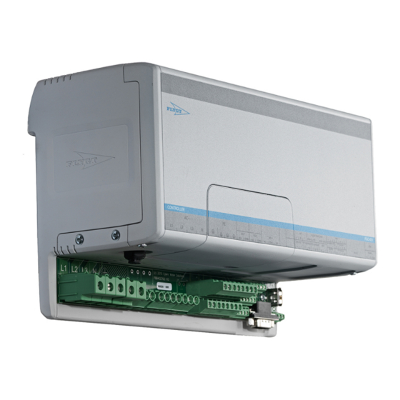
Page 11: Product Description
1-pump, DIN rail, with contactor FGC 401 7991202 DIN-rail, for external contactors FGC 421 7991203 2-pump, DIN rail, with contactors FGC 411 7991204 1-pump, DIN rail, with contactor FGC 401 7991205 DIN rail, for external contactors Flygt FGC 400 Installation, Operation, and Maintenance... -
Page 12: Approvals
Technical Reference (page 55). 3.1.4 The data plate 1. Brand 2. Product 3. Batch number. Edition number. 4. Country of origin. Manufacturer. 5. Approvals 6. Part number 7. Serial number 8. Software version Flygt FGC 400 Installation, Operation, and Maintenance... -
Page 13: System Description
Level device • Analog sensors • Open Bell • Float switches Pumps The controller monitors and controls one or two pumps. Pumps that are rated for currents greater than 12 A require external contactors. Flygt FGC 400 Installation, Operation, and Maintenance... -
Page 14: Function Description
The input must be configured for its intended purpose. – Analog sensor A pressure sensor or an Open Bell sensor is used when the controller is configured for an analog sensor. Flygt FGC 400 Installation, Operation, and Maintenance... -
Page 15: Pressure Sensor
The range is 0 m to 5.1 m (16.7 ft). The lowest water level must sink below the Open Bell level sensor in each pump cycle. 5.2.3 Float switches A float switch provides an input signal at a configured start or stop level. A maximum of five switches is possible. Flygt FGC 400 Installation, Operation, and Maintenance... -
Page 16: Pump Control
If the duty pump is unavailable, then the standby pump becomes the lead pump, regardless of alternation mode. Flygt FGC 400 Installation, Operation, and Maintenance... -
Page 17: Profiles
The alarms that are activated for this function trigger the output signal. 5.5.2 Relay output The control relay is an output that is provided for general purposes. The alarms can be configured to activate the relay. Flygt FGC 400 Installation, Operation, and Maintenance... -
Page 18: Alarm Reset And Silencing
5.6 Running data and history data Running data and history are stored in the controller. The data is also accessible through remote communication. • Present alarm data • Ceased alarm data • Pump information • Well information Flygt FGC 400 Installation, Operation, and Maintenance... -
Page 19: Mechanical Installation
1. Fasten the DIN-rail in the cabinet. 2. Fasten the units to the DIN-rail. a) Fasten the controller. b) Install the HMI. For more information, see the Installation, Operation, and Maintenance manual for the HMI. Flygt FGC 400 Installation, Operation, and Maintenance... -
Page 20: Electrical Installation
These requirements apply for electrical installation: • The mains voltage and frequency must agree with the specifications for the product. • Circuit breakers must be installed between the main voltage line and this unit. Flygt FGC 400 Installation, Operation, and Maintenance... -
Page 21: Connect A 3-Phase Pump Motor To The Internal Contactor
DI 1 DO 1 DO 2 RS485 MUTE P2 H/O/A RS232 Connect the pump cables to the terminals and to protective earth. For pumps rated higher than 12A, an external contactor must be used. Flygt FGC 400 Installation, Operation, and Maintenance... -
Page 22: Connect A An External Contactor For A 3-Phase Pump Motor
Number Terminal Description STOP Stop level switch DUTY Start level switch for the duty pump − Common terminal for all float switches STBY Start level switch for the stand-by pump HIGH High-level switch Flygt FGC 400 Installation, Operation, and Maintenance... -
Page 23: Connect A 4-20 Ma Level Sensor
24V OUT P1 SENSOR P2 SENSOR DI 1 DO 1 DO 2 RS485 MUTE P2 H/O/A RS232 1. Pump 1 2. Pump 2 Connect the pump sensor circuits to terminals T1 and T2. Flygt FGC 400 Installation, Operation, and Maintenance... -
Page 24: Connect An External Current Transformer
HIGH ALARM 24V P1 H/O/A DO 3 24V OUT P1 SENSOR P2 SENSOR DI 1 RS485 DO 1 DO 2 MUTE P2 H/O/A RS232 Connect an external alarm lamp. Maximum current: 100 mA. Flygt FGC 400 Installation, Operation, and Maintenance... -
Page 25: Connect An External Alarm Silencing Or Alarm Reset Signal
RS485 MUTE P2 H/O/A RS232 1. Pump 1 2. Pump 2 Connect the hand-off-auto switch. Auto mode is active if neither H or O is switched to common. Terminal Description Hand − Common Flygt FGC 400 Installation, Operation, and Maintenance... -
Page 26: Connect The Hmi
P2 H/O/A RS232 The communication interface supports Modbus or AquaCom directly over RS-232, or through a modem. 1. Connect the RS-232 cable. 2. Connect the modem power cable to the 24V OUT terminal. Flygt FGC 400 Installation, Operation, and Maintenance... -
Page 27: Connect To The General-Purpose Digital Output
RS232 1. Connect an external switch device to the DI 1 terminals. Maximum +24 VDC. 2. Configure the function of the switch in the HMI: Settings > Pump Control > GP Input Usage. Flygt FGC 400 Installation, Operation, and Maintenance... -
Page 28: Connect A 3-Phase Power Supply
24V OUT P1 SENSOR P2 SENSOR DI 1 RS485 DO 1 DO 2 MUTE P2 H/O/A RS232 Connect the incoming power cables to the power terminals and ground (earth). Terminal Description Phase Neutral Flygt FGC 400 Installation, Operation, and Maintenance... - Page 29 7 Electrical Installation Terminal Description Protective earth Flygt FGC 400 Installation, Operation, and Maintenance...
-
Page 30: System Setup And Operation
The hand button is used to change from auto mode to manual mode. Off button The off button is used to stop the unit or units, when manual mode is used. Auto button The auto button is used to change from manual to auto mode. Flygt FGC 400 Installation, Operation, and Maintenance... -
Page 31: Commissioning
3. Standby Start Level 4. Pump Stop Level Open Bell Select and configure: 1. Duty Start Level 2. Standby Start Level Float Switches Go to the next menu. 3. Continue through the wizard. Flygt FGC 400 Installation, Operation, and Maintenance... -
Page 32: Common Procedures
8.4.1 Modify the start and stop levels This procedure is applicable when an analog sensor is used. Changes of the start and stop levels are reflected in the current profile. Flygt FGC 400 Installation, Operation, and Maintenance... -
Page 33: Configure The General-Purpose Digital Input
1. On the Home menu, select the Well symbol. 2. Select Active Profile. 3. Select and confirm the new profile. 8.4.4 Set the date and time 1. Go to Settings > Global Settings > Date/Time Settings. 2. Open Change Date/Time. Flygt FGC 400 Installation, Operation, and Maintenance... -
Page 34: Enable Or Disable A Function
If the pumps are different, the settings have to be changed. 1. Go to Settings > Motor Protection. 2. Select and configure the following parameters for each pump. – Full Load Current – Overcurrent Threshold – Sensor Type Flygt FGC 400 Installation, Operation, and Maintenance... -
Page 35: Configure The Power On Delay Function
Pump 2 Overcurrent Pump 1 Current Phase Imbalance Wrong connection, damaged motor or tripped fuse. Pump 2 Current Phase Imbalance Pump 1 Leakage Inspect and repair the pump. Pump 2 Leakage Flygt FGC 400 Installation, Operation, and Maintenance... - Page 36 Pump 1 Sensor Short Circuit Thermal contact in pump instead of FLS. Pump 2 Sensor Short Circuit Controller alarms Alarm Probable cause Comms Fail Comms lost to controller. Startup Failure Corrupt unit, try full upgrade. Flygt FGC 400 Installation, Operation, and Maintenance...
-
Page 37: Maintenance
Confirm, and wait for confirmation of the firmware? upgrade procedure. 4. Remove the USB drive. 9.4 Back up the configuration settings The settings are erased at a firmware upgrade. They can be saved to a USB before the upgrade. Flygt FGC 400 Installation, Operation, and Maintenance... -
Page 38: Restore The Configuration Settings
2. Go to Settings > Backup/Restore > Restore from USB > Proceed with restoring configuration from USB? 3. Select the checkmark and confirm. The configuration is restored in the controller. 4. Remove the USB. Flygt FGC 400 Installation, Operation, and Maintenance... -
Page 39: Troubleshooting
3. Check that the configuration settings are correct. For an analog sensor, make sure that the sensor range is correct. 10.3 Check the HMI for faults Follow this procedure when the Comms Fail alarm appears. Flygt FGC 400 Installation, Operation, and Maintenance... - Page 40 2. Make sure that the cable is correctly connected and has no faults. 3. Restart the controller. 4. Upgrade the HMI firmware. 5. For more information, contact the sales and service representative. Flygt FGC 400 Installation, Operation, and Maintenance...
-
Page 41: User Interface
Part Description Status The pump status. • Running • Fault • Stopped Current The load current that the pump uses. Starts The number of starts. Total, today and yesterday. • Today • Yesterday Flygt FGC 400 Installation, Operation, and Maintenance... -
Page 42: Well Information
The stop level for the pump. High Level Activation Level The alarm activation level. High level. High Level Deactivation Level The alarm deactivation level. High level. Low Level Activation Level The alarm activation level. Low level. Flygt FGC 400 Installation, Operation, and Maintenance... -
Page 43: Home
A manual confirmation is required to clear the alarm. Text messages The text message shows the most probable cause of the alarm. For more information, see Alarm information (page 33). Call the service: The service number, if configured. Flygt FGC 400 Installation, Operation, and Maintenance... -
Page 44: History
Global Settings The settings for the site, the date and time, and the HMI configuration. Backup/Restore The dialogs for USB backup or restore of alarm data and statistics. Language The following languages are supported: Flygt FGC 400 Installation, Operation, and Maintenance... - Page 45 Alternation Mode The type of pump alternation mode: • Fixed • Standard • Run Time Maximum Pumps Running • 1 Pump • 2 Pumps Flygt FGC 400 Installation, Operation, and Maintenance...
- Page 46 • Profile 4 Maintenance Run The activation and settings for the function. Interval, in hours, between maintenance runs. Duration, in seconds, of the function. • Enabled • Run Below Stop Level • Interval Flygt FGC 400 Installation, Operation, and Maintenance...
- Page 47 Analog Under Range The measured signal from the analog sensor is lower than the configured range. Analog Over Range The measured signal from the analog sensor is higher than the configured range. Flygt FGC 400 Installation, Operation, and Maintenance...
- Page 48 Pump 1 Current Phase Imbalance The current phase imbalance exceeds a defined limit for a defined time. Pump 2 Current Phase Imbalance The current phase imbalance exceeds a defined limit for a defined time. Flygt FGC 400 Installation, Operation, and Maintenance...
- Page 49 This parameter is configurable for the applicable alarms. Reset Required TRUE: The alarm requires a manual reset. FALSE: The alarm does not require a manual reset. This parameter is configurable for the applicable alarms. Flygt FGC 400 Installation, Operation, and Maintenance...
- Page 50 • Pump 2 Service Interval • Enabled • Interval • Pump 1 • Pump 2 • Pump 1 Overcurrent • Full Load Current • Pump 2 Overcurrent • Overcurrent Threshold • General Settings Flygt FGC 400 Installation, Operation, and Maintenance...
- Page 51 The activation of a test call. Global Settings Part Description Site Name The field for the site name. Date/Time Settings The settings for the date and time. • Change Date/Time • Date/Time Format • Time Offset Flygt FGC 400 Installation, Operation, and Maintenance...
-
Page 52: Inputs And Outputs
The controller system information. Digital Inputs Part Description Pump 1 OFF The input state for the off signal. Pump 1. ON, OFF Pump 1 HAND The input state for the hand signal. Pump 2. ON, OFF Flygt FGC 400 Installation, Operation, and Maintenance... - Page 53 Phase 12 The voltage phase angle between phase one and two. Phase 23 The voltage phase angle between phase two and three. Phase 31 The voltage phase angle between phase three and one. Flygt FGC 400 Installation, Operation, and Maintenance...
- Page 54 The digital output for the buzzer in the controller. ON, OFF System Information Part Description System 24 V The voltage input to the controller. System Current The current in the controller. Internal Temperature The controller temperature. Flygt FGC 400 Installation, Operation, and Maintenance...
-
Page 55: Setup Wizard
The incoming nominal voltage. Line to line for 3-phase. Line to neutral for single phase. Full Load Current The maximum full load current. Sensor Type The sensor type. • FLS • Thermal Switch Flygt FGC 400 Installation, Operation, and Maintenance... -
Page 56: About
This option leads to a complete reset of the HMI. Factory Reset This option leads to the setup wizard or to the option to restore the configuration from a USB drive. The existing configuration is reset to factory default. Flygt FGC 400 Installation, Operation, and Maintenance... -
Page 57: Technical Reference
12.4 Electrical data Parameter Value Supply voltage • 3-phase: – 200–460 VAC with neutral – 400–415 VAC without neutral • 1-phase: 100–265 VAC Frequency 50 Hz or 60 Hz Supply voltage tolerance ± 10% Flygt FGC 400 Installation, Operation, and Maintenance... -
Page 58: Terminals
Protective earth for pumps and extra equipment Up to: 2.5 mm Relay output for external contactor. – – 250 VAC, 5 A Pump 1 Relay output for external contactor. – – 250 VAC, 5 A Pump 2 Externally fused Flygt FGC 400 Installation, Operation, and Maintenance... - Page 59 – Configurable − 1: 0 V CAN bus cable to HMI 2: CAN L 3: Screen 4: CAN H 5: +24 V Digital output for 24 V alarm lamp Maximum 100 mA − Flygt FGC 400 Installation, Operation, and Maintenance...
-
Page 60: Source Code
– Maximum 460 VAC Maximum 12 A Up to: 2.5 mm Pump 2 12.6 Source code BSD License for U8glib Code Universal 8bit Graphics Library (http://code.google.com/p/u8glib/) © Copyright 2011, olikraus@gmail.com All rights reserved. Flygt FGC 400 Installation, Operation, and Maintenance... - Page 64 For more information on how Xylem can help you, go to xyleminc.com Xylem Water Solutions Global Visit our Web site for the latest...
Need help?
Do you have a question about the Flygt FGC 400 and is the answer not in the manual?
Questions and answers