Table of Contents
Advertisement
Quick Links
Advertisement
Table of Contents
Troubleshooting

Related Manuals for Delta DelREMO-V2.0


Summary of Contents for Delta DelREMO-V2.0
- Page 1 User Guide (Indoor) DelREMO-V2.0 www.deltaelectronicsindia.com •...
- Page 2 •...
- Page 3 About this guide Purpose This guide explains the method to install and configure the DelREMO-V2.0 system. This guide serves as a quick reference guide for engineers and technicians operating the system. Intended reader This guide is written for the trained engineers and technicians to facilitate installation and configuration of the DelREMO-V2.0 system.
- Page 4 THE INFORMATION CONTAINED IN THIS DOCUMENT IS PROVIDED ON AN “AS IS” BASIS. In no event will Delta be liable for damages arising directly or indirectly from any use of the information contained in this document.
-
Page 5: Table Of Contents
Unpacking the consignment ................. 7 1.5.1 Follow check list ..................... 7 1.5.2 Handling tips ......................7 1.5.3 Preliminary inspection .................... 7 DelREMO-V2.0 System Overview ..................8 System Description....................8 Introduction to different sections ................9 Technical Specifications ..................10 Installation procedure ..................... 12 Steps involved in installation ................ -
Page 6: Handling And Safety Information
The user is responsible for ensuring the restricted access of DelREMO-V2.0 system. • If the power supply to the DelREMO-V2.0 system is not fitted with a disconnecting switch or equivalent device, the operator is responsible for fitting an appropriate disconnection switch conforming to the relevant regulations. -
Page 7: Unpacking The Consignment
1.5.1 Follow check list • Check the received consignment according to the check list. • Contact the transport authorities and Delta if any item is missing as per the list of contents. 1.5.2 Handling tips DelREMO-V2.0 system is light weight equipment; need to be handled very carefully while installing else may damage internal components. -
Page 8: Delremo-V2.0 System Overview
System Description DelREMO-V2.0 is designed with high end 32 bit RISC processor which collects data from different solar inverters and sensors, and sends them to remote server using high speed GPRS/GSM modem or LAN connectivity. -
Page 9: Introduction To Different Sections
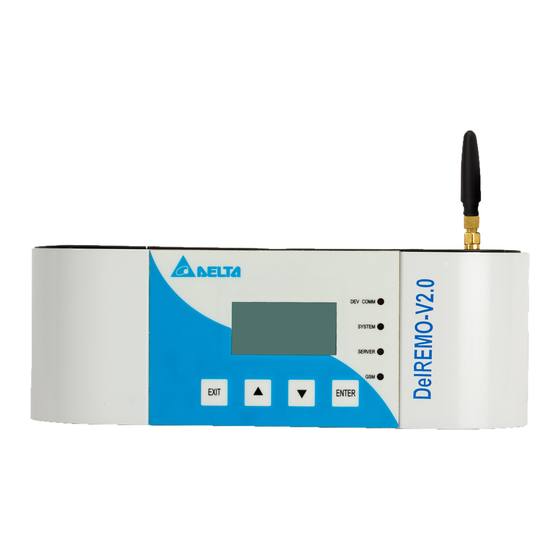
DelREMO-V2.0 to make it functional in efficient way. Introduction to different sections Before starting with installation and commission let’s get introduced to the important sections of DelREMO-V2.0 SYSTEM, showing in fig 2.2. Introduction to different sections will facilitate the installation procedure. Fig 2.2 Isometric view of DelREMO-V2.0 Fig 2.3 Front view of DelREMO-V2.0... -
Page 10: Technical Specifications
Fig 2.4 Bottom view of DelREMO-V2.0 Fig 2.5 Top view of DelREMO-V2.0 The DelREMO-V2.0 supports following features and interfaces:- • 4 nos. of 0 to 10 VDC analog inputs for sensor integration like irradiance, pyranometer, temperature etc. • 4 nos. of 4 to 20 mA DC analog inputs for sensor integration like, wind speed, humidity temperature etc. - Page 11 Table 2.2 User interface User Interface System Config. Using LAN & Keypad Time and Date Real time date and Programmable Event log >200K Local Monitoring Thru Ethernet Port (Embedded Web server) & LCD Table 2.3 General specification General Op. Temp 0ºc to 60º...
-
Page 12: Installation Procedure
Installation procedure Installation procedure explains the standard procedures to be followed during the installation of the DelREMO-V2.0 system. Read the safety instructions and warnings carefully and completely before initiating the installation procedure. During the installation procedure ensure that the standard steps are followed strictly. Create a check list involving the various steps of installation and follow them carefully for the complete and successful installation of the DelREMO-V2.0 system. - Page 13 Check for any damage to the LCD. Step 3:→ System Mounting DelREMO-V2.0 is fully internally fitted and completely connected at the factory. System mounting and input/output connections along with necessary connections to various power sources and connections are made at the installation site. DelREMO-V2.0 is to be mounted on wall •...
- Page 14 • Move the DelREMO-V2.0 downwards as shown below. Note that slot represented locks with hooks provided in wall Fig 3.2 DelREMO-V2.0 Wall Mounting Arrangement Step 4:→ System Handling While opening and closing the top cover of DELREMO system, special attention is required towards LCD connector, as the top cover may damage LCD’s harness while opening and closing.
-
Page 15: Basic Interconnection Steps
Basic interconnection steps DelREMO-V2.0 involves the following basic interconnection steps. The following connection check list is done to avoid connection problems. Steps for input connection Check Serial Connect all the sensors output to DelREMO at their respective position & provide power from system is required. -
Page 16: System Commissioning
4.1.1 System start up precautions DelREMO-V2.0 works with 24V DC voltage, extra care should be taken while operating the system. Read and follow precautions mentioned below carefully while starting up the commissioning of the system. -
Page 17: System Configuration
V2.0 4.1.3 System Configuration After DelREMO-V2.0 is powered ON, connect the DelREMO to Laptop/PC via Ethernet port provided at the bottom of unit using RJ45 cable. Following settings are to be done on Laptop/PC to access the DelREMO: Click on Start TAB, and then go to Control Panel TAB as Shown below. - Page 18 •...
- Page 19 VIII. TURN OFF ALL PROXY SETTING & FIREWALL BEFORE PROCEEDING TO NEXT STEP. NOTE n off proxy settings go to (PATH: Control Panel>Internet Option) At Internet Properties TAB click on Connections, then click on LAN Settings TAB. a. Un-tick Proxy server. b.
- Page 20 Pushpak II Controller Web page configuration Now open Google Chrome browser on your laptop. In Address Bar type the following IP address 192.168.100.30 and press Enter Key. •...
- Page 21 XII. After clicking on “Click here for Login” Tab, a pop up window will appear, enter user name and password as captioned below Fill User Name → admin to logged in. Password → delta XIII. After Log in, Window will appear as below •...
- Page 22 1. Signal Strength 6. Help Tab 2. LED indications 7. Logout Tab 3. Reset Tab 8. Firmware Version 4. Date & Time Menu tab 5. Site ID, site Name XIV. Upload firmware file by following Path - Upload>Firmware>DelRemo. ▪ Click on Choose File Tab to select Firmware version, as shown. ▪...
- Page 23 After successful transfer of Firmware a message will appear as shown below. XVI. To Set/Verify Modem Setting go to Interface>Modem and do settings as mentioned below. User can Enable/Disable desired SIM. SIM 1 Status ENABLE SIM 2 Status DISABLE APN: Manual Internet IDEA SIM airtelgprs.com...
- Page 24 XVII. Follow below path to enter Site Configuration ▪ Configure>Site and populate Site ID, Site Name along with address associated. ▪ Provide the count of inverter available at site which is going to be monitored at Inverter Settings. ▪ Do select energy meters Model if available at site otherwise keep this setting as “Disable”. Also put no.
- Page 25 XVIII. Follow below path to enter Server configuration page and populate below setting Configure>NOC ➢ IP/Domain Name : DelREMO.emonitoring.co.in ➢ Port : 4015 ➢ Interface : Ethernet (Primary Server), GPRS (Backup Server) SMS No. : +918750069315 ➢ Periodicity ➢ Server IP : 172.24.2.18 ➢...
- Page 26 XIX. Follow below Path to enter DelREMO Ethernet configuration setting. Configure> Ethernet and submit thereafter to save the setting. Follow Below path to enter “Auto Update setting”. Configuration> Auto update Settings Do setting as prescribed in below snap. •...
- Page 27 XXI. Use below path to reach clock configuration setting. Configure>Clock There are 3 methods to set clock for DelREMO device 1) SNTP: Customer can use this method if wants to synchronize DelREMO on their NTP server. 2) NITZ: Network Identity and Time zone is a mechanism often used to update system clock automatically using GSM network.
- Page 28 XXII. Set Master Mobile No. Following below path Upload>Database>Master Mobile No. Set Master Mobile No. as:- ➢ user1:- +919540524222 ➢ user2:- +918527000445 ➢ user3:- +91XXXXXXXXXX ➢ user4:- +91XXXXXXXXXX ➢ user5:- +91XXXXXXXXXX From user3 to user5, mobile no. of Site Technician, CI, ZOM etc. can be configured as per customer requirement.
- Page 29 XXIII. Follow below path to enter sensor configuration setting Configure>Sensor There are 4 attributes being used to manipulate sensor values as per customer requirement and these are as follows: Name: This is used name sensor depends upon their type and the nature of reading it provided. Type: This field enables/disabled the effect of offset and multiplier into the original value supplied by sensor.
- Page 30 XXIV. Power generation can be regulated at any point of time in steps depending upon the load requirement. On getting input from string Box, it reduces the potency of Inverter to generate power in steps (Can be customized) whenever it found the generated power is exceeding the power required at load to avoid unwanted power loss.
- Page 31 XXVI. One can learn energy meter parameters through tapping on EM Status. XXVII. Tap on Inverter status to learn various parameters coming from Inverter configured with DelREMO. •...
-
Page 32: Settings Through Lcd
4.1.4 Settings Through LCD Step Process Image Press ENTER key After pressing ENTER key, a menu will appear having 3 option: GSM CONFIG ETH CONFIG SITE CONFIG Select GSM CONFIG using UP & Down Key & Press ENTER key. After pressing Enter key, two options will come. - Page 33 After pressing ENTER key, it will ask for confirmation for save changes. Select YES to Save. After selecting YES, press ENTER Key. After pressing ENTER KEY, confirmation message will appear as “SETTING SAVED SUCCESSFULLY” Now go to ETH CONIG in main Menu. Select ETH CONFIG &...
- Page 34 IP address configuration: Follow below path by pressing ENTER ETH CONFIG→IPADDRESS By pressing UP or DOWN key you can change the desired digit. For moving to the other digit press ENTER key. Follow step 5 & 6 to save changes. SUBNET MASK Configuration: Follow below path by pressing ENTER ETH CONFIG→SUBNET MASK...
- Page 35 PRIMARY DNS CONFIGURATION: Follow below path by pressing ENTER ETH CONFIG→PRIMARY DNS By pressing UP or DOWN key you can change the desired digit. For moving to the other digit press ENTER key. Follow step 5 & 6 to save changes SECONDARY DNS CONFIGURATION: Follow below path by pressing ENTER ETH CONFIG→SECONDARY DNS...
-
Page 36: Basic Functional Verification
SITE CONFIGURATION: ENERGY METER Follow below path by pressing ENTER MENU→SITE CONFIG→ENERGY METER By pressing UP or DOWN key you can change select ENABLE or DISABLE option. For moving to the other digit press ENTER key. Follow step 5 & 6 to save changes 4.1.5 Basic functional verification After commissioning of DELREMO SYSTEM let’s move to basic functional verification. -
Page 37: System Calibration Procedure
& verify site data. 4.1.7 System calibration procedure The system is pre-calibrated by Delta Power Solutions. Calibration is not needed unless some changes have been made to the System hardware or the interfacing sensors is different from measurements made with calibrated test equipment during maintenance. -
Page 38: Modes Of Operation
Step 8. Go to Upload>Database>Master Mobile No. for entering mobile no. of user who has read/write access of the system. Modes of operation DelREMO-V2.0 can send data to remote server thru following modes: - 4.2.1 Mains Mode This mode confirms that a main AC is available to 24 VDC adapter, adapter is generating 24VDC nominal output to DelREMO-V2.0 SYSTEM as the device works on 24VDC. -
Page 39: Introducing Alarm System And Troubleshooting
DelREMO-V2.0 provides system status indicators through both the LED and web user interfaces. The LEDs on the front panel of the DelREMO-V2.0 are used to give an initial indication of the severity or type of fault. The normal assignments of the LEDs are shown in table. -
Page 40: Troubleshooting
NOTE 5.2.4 Unresolved problems If an alarm or specific problem cannot be resolved, please contact your nearest Delta office or Delta representative for further assistance. Please have the system type and serial number ready before contacting Delta. Contact details are discussed in the customer care support. -
Page 41: Maintenance
Maintenance DelREMO-V2.0 SYSTEM is a fully automatic system and does not require frequent maintenance. There are no customer serviceable parts inside the system, but some of the parts and sections require attention and periodic look after. Maintenance includes cleaning of system parts which comes in direct contact of dust. -
Page 42: Customer Care Support
6.3 Customer care support Contact customer care helpline numbers for any query and service related issues. Customer care helpline +91-7676254716 •... - Page 43 Delta. Trademarks DELTA is a Trademark. Its name mentioned in this manual should not be understood as advertising for the product or their manufacturers. The authors reserve the rights to make any changes to this product and to revise the information about the products contained in this guide without an obligation to notify any persons about such revisions or changes.
- Page 45 ecycle paper Save earth...
Need help?
Do you have a question about the DelREMO-V2.0 and is the answer not in the manual?
Questions and answers