
Related Manuals for Delta PPM DC1_100


Summary of Contents for Delta PPM DC1_100
- Page 1 The power behind competitiveness Delta Data Collector PPM DC1_100 Installation Manual www.deltaww.com...
-
Page 2: Table Of Contents
Contents ■ Introduction ■ ........... . . ... -
Page 3: Precautions For Your Safety
■ Notations for safe use of the product and their meanings This Instruction Manual provides precautions with the following notations and symbols for safe use of the PPM DC1_100. The expression “Product”, “Data Collector” or “DC1” refers to the PPM DC1_100. Precautions described herein contain important aspects of safety. - Page 4 Warning Do not allow any fire producing objects to be near the Product, or apply any spray, including combustible gases, to the Product. The Product may ignite or explode in the unlikely event such an occurrence takes place. Do not touch the Product with wet hands. The Product may cause injury due to electric shock or equipment malfunction may occur in the unlikely event such an occurrence takes place.
-
Page 5: Essential Points For Safety
・ Pull 16-pin terminal and Power supply terminal off when any abnormality is detected like smoke, heat. ・ Install the product with the “DELTA” logo facing front when in stalling the Data Collector on a wall. ・ Take care to ensure no water or other liquid gets on the Data Collector. -
Page 6: Preparation Before Construction
1.Preparation before construction 1.1.Scope of Delivery Verify that following items are available for use prior to using this feature. Product name Remarks Shape Data Collector 1 unit Main unit Wi-Fi Antenna 1 piece Install antenna to Enhance Wireless Signals. DIN Rail 1 piece This is a rail used to install the product on a wall. -
Page 7: Dimension
1.2.Dimension 55 mm 72 mm Din Rail 125±1 3.5±0.5 unit: mm... -
Page 8: Descriptions And Functions Of Parts And Components
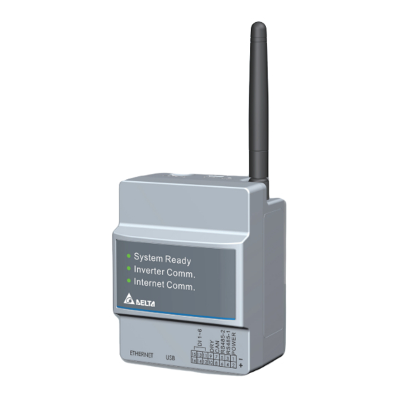
1.3.Descriptions and Functions of Parts and Components ①MICRO SD POWER IN Use SD card to reset Data Collector to factory default. The settings and records will be deleted. ②Power supply terminal Power supply terminal of Data Collector. (Input Voltage: 5V) ③Reset button Resetting the Data Collector. -
Page 9: Reset Method
1.4.Reset Method Press reset button System ready led flashing Action of DC1 POWER IN 3~5 sec 0.5sec ON, 0.5sec OFF Rebuild wifi module Reset wifi password and 6~10 sec 1sec ON, 1sec OFF rebuild wifi module Reset DC1 setting without SN, Over 15sec 2sec ON, 2sec OFF then reboot... -
Page 10: Installation
2.Installation 2.1.Installation on wall 1. DC1 (1) Use the supplied DIN Rail and mount in distribution cabinet (A). (2) Fix the Data Collector on top of the DIN Rail.(B) (3) Buckle the Data Collector on the DIN Rail.(C) (4) Install two stoppers on the DIN Rail on both side of the Data Collector, then lock in the screws on stoppers to fix these stoppers on the DIN Rail.(D) 2. -
Page 11: Installation In Box (Outdoor)
* If the external box is made of metal, Wi-Fi antenna needs to be installed outside the box (F). User needs to use extension cable to connect the Wi-Fi antenna. (2) An external box is available for customer from Delta. Contact retailer for more details. 2. DC1 + SUB_1G (N1) -
Page 12: Setting Connectors And Cables
2.3.Setting Connectors and Cables ● Setting cables Prepare 0.3 to 0.5mm x single wire, 4 cores (twin wires) shielded cables (rated temperature: 80ºC to 85ºC). * Process the cables before use. Φ 0.6~0.8 Φ 5~6 Cable 40mm ● Assemble 16-pin connector Hold down the pin ①... -
Page 13: Connection To The Inverter
2.4.Connection to the inverter RS-485 DC1 Data collector Inverter See manual of the inverter 0.3 ~ 0.5 mm DC1 Data collector Inverter Power - GND RS485 - GND Power - + RS485 - 12/24 V RS485 - DATA– RS485-1 - B CAT5 / CAT6 RS485-1 - A RS485 - DATA+... -
Page 14: Download The App
Use the wrench to lock antenna with 1.2 N•m torque. 2.5.Download the APP MyDeltaSolar 1. This APP should collocate with Delta Inverter. 2. If inverter is not connected to cloud, you still can monitor inverter operation by APP. 3. Scan QR code for APP operation manual. -
Page 15: Supported Inverter Models
3.Supported inverter models 3.1.Normal mode Inverter connect with DC1 via Wired (RS-485) or Wi-Fi, DC1 transfer inverter data to Delta Cloud or 3rd party monitoring device. ● Connection type DC1 - inverter Wired (RS485) Wi-Fi Mixed SUB_1G Wired: max 32 inverters... -
Page 16: Specifications
4. Specifications ELECTRONIC SPEC PPM DC1_100 Operating voltage range 9Vdc ~ 25Vdc (power port, can be supplied from inverter), 5Vdc (Micro USB) Power Consumption 5 Watt COMMUNICATION Wired RS-485/ Ethernet Wireless Internal Wi-Fi Module 802.11a/b/g/n REGULATION Safety Standard EN 61010-1, CE compliance... -
Page 17: When Something Seems Wrong (Troubleshooting)
5. When Something Seems Wrong (Troubleshooting) 5.1.Error Displays When a problem occurs, confirm the Error message from the [ERROR EVENTS LOG] page of [History]. Details can be verified in the “ERROR EVENTS LOG” pages. Refer to the Manual of the Inverter for details on the error codes. -
Page 18: Troubleshooting
5.2.Troubleshooting Responsive actions that should be taken in cases where the following symptoms occur are described. Symptom Verification details Responsive action DC1 is booting Please wait two minutes for the boot to complete System ready light is red DC1 is Searching or Setting Please wait for 2-10 minutes for Inverter to search or inverters. -
Page 19: Appendix - N1
Appendix - N1 1. Functions of Parts TOP VIEW Part Function Antenna Wi-Fi Single External Comm. Connection to Data Collector Connector Fixed Point Fix with Data Collector Power LED Power ON/OFF Sub-1G LED Sub-1G status Reset Button Reset to Default 2. - Page 20 4. Specifications PPM N1 _ SB1 ELECTRONIC SPEC Operating voltage range 5 Vdc Power Consumption 2 Watt COMMUNICATION Wired RS-485 SUB _ 1G Wireless REGULATION Safety Standard EN 61010-1, CE compliance Emission (EMI) EN 300 220 (below 1G), EN 50385, LP0002, Part 15C, Telec T66 Immunity(EMS) EN 301 489-1/-3, EN 55024, EN 55032, FCC Part 15B CONNECTION...
-
Page 21: Appendix - N2
Appendix - N2 1. Functions of Parts Part Function Antenna Wi-Fi Single Fixed Point Fix on inverter Reset Button Reset to default Power LED Power ON/OFF Status LED Sub-1G Status Cable Gland Avoid the moisture into machine 2. SUB _ 1G Antenna ■... - Page 22 4. Specifications PPM N2 _ SB1 ELECTRONIC SPEC Operating voltage range 12 Vdc Power Consumption 2 Watt COMMUNICATION Wired RS-485 SUB _ 1G Wireless REGULATION Safety Standard EN 61010-1, CE compliance Emission (EMI) EN 300 220 (below 1G), EN 50385, LP0002, Part 15C, Telec T66 Immunity(EMS) EN 301 489-1/-3, EN 55024, EN 55032, FCC Part 15B CONNECTION...
-
Page 23: Appendix - P1
Appendix - P1 1. Functions of Parts Mains voltage connector block CT wire connector Connect with Data Collector Meter status LED Reset Button RS-485 port & terminal resistor port 2. LED Description Status Explanation Hardware failure Blink No communication from other device Green Normal Green... -
Page 24: Appendix - P3
Appendix - P3 1. Functions of Parts Mains voltage connector block CT wire connector Connect with Data Collector Meter status LED Reset Button RS-485 port & terminal resistor port 2. LED Description Status Explanation Hardware failure Blink No communication from other device Green Normal Green... - Page 25 20210223...
Need help?
Do you have a question about the PPM DC1_100 and is the answer not in the manual?
Questions and answers