Table of Contents
Advertisement
Quick Links
This guide explains the installation, configuration and operation of the EXIFU-A1 and EXIFU-B1
option cards for the XN120 Telephone System.
Further information will be supplied with any optional equipment that you have purchased.
Refer to the Getting Started Guide supplied with the XN120 main unit for further detail and
Administrator User Guide.
Please keep all information supplied for future reference.
Regulatory Notice.
Refer to the Getting Started Guide (991409-5) supplied with the XN120 Main Unit for the Declaration
of Conformity related to the product.
Warning: This is a class A product. In a domestic environment this product may cause radio
interference in which case the user may be required to take adequate measures.
XN120
EXIFU Guide
Rev 1.1 February 2005
991423-5
Advertisement
Table of Contents

Related Manuals for NEC EXIFU-A1


Summary of Contents for NEC EXIFU-A1
- Page 1 This guide explains the installation, configuration and operation of the EXIFU-A1 and EXIFU-B1 option cards for the XN120 Telephone System. Further information will be supplied with any optional equipment that you have purchased. Refer to the Getting Started Guide supplied with the XN120 main unit for further detail and Administrator User Guide.
-
Page 2: Table Of Contents
Contents What is the EXIFU?...............................3 System Connection Diagram..........................3 Installation Procedure ............................4 1- Unpack the Card...............................5 2- Install the EXIFU ...............................6 3- Test the EXIFU ..............................8 4- Configure the EXIFU............................10 XN120 Configuration Mode ..........................11 Ethernet Port ...............................13 Ethernet Port Specification..........................14 Ethernet Cable ..............................14 Fit the Ferrite Core to the Ethernet Cable ......................14 Maximum Cable Length ...........................14... -
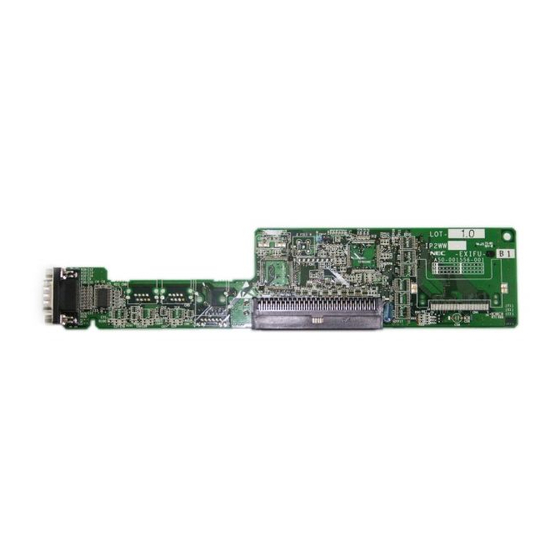
Page 3: What Is The Exifu
System Connection Diagram What is the EXIFU? There are two types of EXIFU card available for the XN120 system. Note that only one EXIFU card can be installed. The EXIFU-A1 option card provides: · Ethernet port Serial Expansion Ethernet Compact Flash ·... -
Page 4: Installation Procedure
Installation Procedure Installation Procedure Unpack the EXIFU card You will also need to power off any expansion units if they are Power off the XN120 and installed. install the card Power on the XN120 Test the EXIFU Configure the EXIFU XN120 EXIFU Guide... -
Page 5: 1- Unpack The Card
There are no cables supplied with the EXIFU. Additional Items Required: · Cross head screwdriver. The EXIFU-A1 card will require: · LAN Cross Cable (or LAN Straight cable connected to a hub) for PC Programming. · Serial Null Modem Cable (9 pin female to 9 pin female) for SMDR. -
Page 6: 2- Install The Exifu
Install the EXIFU Card 2- Install the EXIFU ! Observe anti-static precautions when handling the EXIFU card. · Wear a suitable anti-static strap connected to an Earth point. One EXIFU card is installed onto the base board within the XN120 main unit. The EXIFU will be automatically assigned when the system is powered on, after the card is installed. - Page 7 Install the EXIFU Card Power on the XN120 system If you have any expansion units installed you must power these on first. The EXIFU card will be automatically configured. ! System Start Up – Retain Customer Configuration This is the normal operation for powering the XN120 on. Before you power on the system check that the NORMAL switch is set to ON.
-
Page 8: 3- Test The Exifu
Test the EXIFU Card 3- Test the EXIFU Test the Ethernet port You will need to connect the Ethernet port of the XN120 to a Network Interface Card (NIC) on your PC. Connect directly via the LAN cross cable. Set your NIC card to the following fixed IP address. See later in this guide for cable connections of the Ethernet IP Address = 172.16.0.11... - Page 9 Test the EXIFU Card port -none- -none- Not Install -none- -none- Not Install -none- -none- Not Install -none- -none- Not Install -none- -none- Not Install -none- -none- Not Install -none- -none- Not Install -none- -none- Not Install -none- -none- Not Install -none- -none- Not Install...
-
Page 10: 4- Configure The Exifu
Configure the EXIFU Card 4- Configure the EXIFU Before you configure your system it is important that you: · Ensure the power will not be turned off to the XN120, otherwise you will lose any changes you have made that were not previously saved to battery backed memory. ·... -
Page 11: Xn120 Configuration Mode
Configure the EXIFU Card XN120 Configuration Mode Entering Configuration Mode · You will need an XN120 system phone with an LCD display. · The phone should be idle (no call in progress). Press SPK You will see - 16:28PM (do not lift the handset) EXT200 Dial Service Code # * # * You will see -... - Page 12 Configure the EXIFU Card Making Changes · With the Program Number entered and the curser positioned at the first entry you can change the value by entering the new one with the numeric keys of the XN120 phone. · When you have entered the new value press HOLD to confirm it and move to the next entry. ·...
-
Page 13: Ethernet Port
The Ethernet port of the XN120 is used for the following feature. PC Programming – PC based application used to configure the XN120 system The Ethernet port will operate when the EXIFU-A1 card is installed, there is no configuration required in order to use PC Programming. -
Page 14: Ethernet Port Specification
Fit the Ferrite Core to the Ethernet Cable Ensure that you make 1 turn of the Ferrite Core Ethernet cable through the ferrite core supplied with the EXIFU-A1 card. Ethernet Cable (CAT5) The diagram shows 1 turn of the cable through the ferrite. -
Page 15: Serial Socket - Call Logging (Smdr)
Call Logging (SMDR) Serial Socket - Call Logging (SMDR) The serial port of the EXIFU-A1 or EXIFU-B1 can be used to output call information for the telephones connected to the system. You would normally collect the call information with a compatible call logging application loaded onto a separate PC. -
Page 16: Set The Baudrate For The Serial Port
Call Logging (SMDR) Set the Baudrate for the serial port. You must set the Baudrate of the XN120 serial port to the same as the COM port of the PC connected to it with program 10-21-02. Program 10-21-02 10-21-02 Set the Baudrate of the serial COM Baud Rate port of the EXIFU card. - Page 17 Call Logging (SMDR) Configuration Sheet: SMDR Serial port Baud rate 0=4800bps Program 10-21-02 1=9600bps 2=19200bps 3=38400bps Default=2 SMDR output 0=Not output 1=Output Program 35-01-01 Default=0 SMDR output for each trunk SMDR output for each telephone Program 14-01-06 Program 15-01-03 Trunk port 0=Not output Trunk port 0=Not output...
-
Page 18: Sample Smdr Report
Call Logging (SMDR) Sample SMDR Report 09/01/03 PAGE 001 CLASS TIME LINE DURATION STATION DIALLED No./CLI RD/COST ACCOUNT 01 POT 10:44 LINE 001 00:00:30 STA 224 12039265400 8841 02 POT 10:46 LINE 001 00:00:45 STA 224 18874521 03 POT 10:47 LINE 001 00:00:29 STA 218 12039265441 04 PIN... - Page 19 Call Logging (SMDR) SMDR Report Format Character Position Field Definition Header Line 1-60 Spaces 61-70 MM/DD/YYYY Space 72-75 PAGE Space 77-79 Report page number (e.g., 001) CR & LF Header Line 2 Spaces CLASS 9-10 Spaces 11-14 TIME 15-18 Spaces 19-22 LINE 23-26...
-
Page 20: Smdr Output Options
Call Logging (SMDR) SMDR Output Options You can change the information output via the SMDR. The following options are available. Omit dialed digits The SMDR will replace the dialed digits with an X character. This will prevent the administrator seeing the exact number dialed but will not prevent any billing operation of the call logging application. - Page 21 Call Logging (SMDR) Minimum ring duration The SMDR will only output the call record if the minimum ring duration is reached for incoming abandoned calls. An abandoned call is shown as NO ANSWER on the SMDR. This timer does not affect calls that are answered. Program 35-01-07 Use Vol.
- Page 22 Call Logging (SMDR) Extension name or number The SMDR can either enter the extension name or extension number in the STATION field for each call record. The extension name is set in program 15-01-01. CLASS TIME LINE DURATION STATION DIALLED No./CLI RD/COST ACCOUNT 01 POT 10:44 001...
- Page 23 Call Logging (SMDR) DDI Name output The call records for incoming ISDN DDI calls can show the name assigned to the DDI in the LINE field. The DDI names are assigned in program 22-11-03 for each DDI number. CLASS TIME LINE DURATION STATION...
- Page 24 Call Logging (SMDR) DDI or CLIP number output The call records for incoming ISDN DDI calls can show the DDI number instead of the CLIP number in the DIALLED No./CLI field. CLASS TIME LINE DURATION STATION DIALLED No./CLI RD/COST ACCOUNT 01 IVIN 10:44 001 00:00:30 STA 224...
- Page 25 Call Logging (SMDR) Configuration Sheet: SMDR Options Program Description Setting Options 0 = None 35-01-04 Omit dialed digits 1-24 = Number of digits omitted Default=1 0 = No minimum 35-01-05 Minimum dialed digits 1-24 = Number of minimum digits Default=0 0 = No minimum 35-01-06 Minimum call duration...
-
Page 26: Serial Cable
Call Logging (SMDR) Serial Cable The serial cable used to connect the EXIFU card to the PC must be a null modem type (cross cable). The following connections are required. The EXIFU card has a 9 pin male D-Type connector. The cable must not exceed 15 metres long. -
Page 27: Compact Flash Socket
Compact Flash Compact Flash Socket The compact flash socket of the EXIFU-A1 card can be used for either saving/re-loading the system configuration or upgrading the XN120 main unit’s firmware. Saving the system configuration You can save a copy of the customer configuration that can be re-loaded in the event of system failure. -
Page 28: System Report
Compact Flash System Report It is recommended that you also output the XN120 system report. This will show the cards installed in each slot and the ports assigned. You will need to connect the serial port of the EXIFU card to a COM port of your PC, refer to Testing the EXIFU earlier in this guide for details. -
Page 29: Loading The System Configuration
Compact Flash Loading the system configuration The customer configuration can be re-loaded from the compact flash card into the XN120 main unit. Note. The configuration on the compact flash card will contain the card type and port assignment of all slots in the system. -
Page 30: Upgrade The Xn120 Main Unit Software
Compact Flash Upgrade the XN120 Main Unit Software The operating system software of the XN120 system can be upgraded by installing a compact flash card into the socket of the EXIFU card. The compact flash card has the new revision of XN120 system software copied onto it. You can confirm the revision of the XN120 system software at any XN120 telephone with a display. - Page 31 Compact Flash To upgrade the XN120 system software. It is recommended that you save the system configuration to the compact flash card before you perform the upgrade; see Saving the System Configuration above. Remove the sub and main covers of the XN120 main unit. Insert the compact flash card Ensure the lamp LED1on the EXIFU card comes ON, this confirms the into the socket on the EXIFU...
- Page 32 Compact Flash Set the NORMAL switch to The NORMAL switch is located on the right side of the MOH/PAGE socket on the XN120 main unit. ! If you do not set the NORMAL switch to ON you will erase the customer configuration when you power on the system Power on the XN120 system...
-
Page 33: Expansion Socket
Expansion Socket Expansion Socket Refer to the guide supplied with the expansion unit. XN120 EXIFU Guide...
Need help?
Do you have a question about the EXIFU-A1 and is the answer not in the manual?
Questions and answers