
Related Manuals for AFL WDM900


Summary of Contents for AFL WDM900
- Page 1 Test & Inspection WDM900 Lightwave Test Set User’s Guide www.AFLglobal.com or +1 (800) 321-5298, +1 (603) 528-7780...
-
Page 2: Table Of Contents
Table of Contents Introduction ............3 Hardware Overview . -
Page 3: Introduction
Channel Detail display, which shows graphically and numerically how measured attributes compare to the acceptance criteria . Within just seconds of connecting to a network port, WDM900 users know the status of each channel, which channels require attention and exactly what action is required . -
Page 4: Hardware Overview
Hardware Overview Controls, Ports, and Features # Feature Description 1 Test Port An optical port accepts AFL’s thread- on adapters (SC, FC, LC; UPC ferrules only) . This test port is used for connection to CWDM/DWDM-based access network . 2 Dust Cap Used to protect an optical port from dust and damage . - Page 5 Description 9 Power Port AC power adapter/charger input . 10 Mini-USB Port This Mini-USB port is for AFL test purposes only . 11 USB Host Port This USB port may be used to transfer test reports to a USB Flash Drive .
-
Page 6: Front Panel Keys And Indicators
Hardware Overview Front Panel Keys and Indicators... - Page 7 Indicator • GREEN light ON indicates that battery is fully charged . Power Key Press and hold (~2 seconds) to turn the WDM900 on or off . Power Indicator This indicator Illuminates when the WDM900 is turned on . Capture Key Press to capture the displayed test results .
-
Page 8: Product Overview
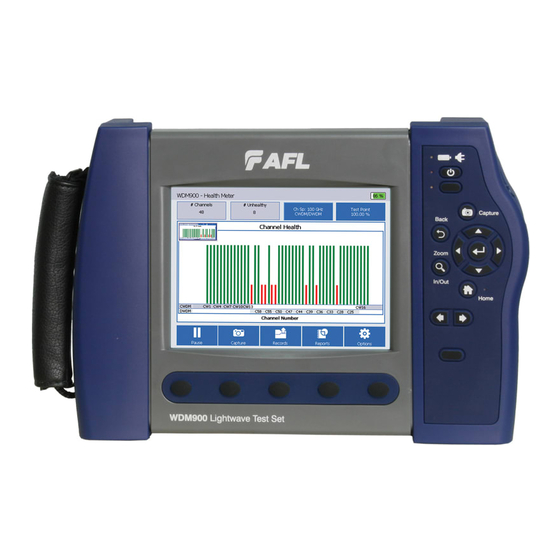
Product Overview Health Meter Mode The Health Meter mode screen is the main screen that the user will see when the WDM900 powers (-60) (-40) up . When the powered up WDM900 is connected to a live CWDM/DWDM or DWDM network, the user will see the Health Meter mode screen similar to the image below . - Page 9 OSNR, and the maximum channel frequency shift tolerance . The WDM900 is initialized with factory default values for these criteria, which can be edited by the user within valid ranges . Healthy (GREEN) channels meet or exceed all criteria .
-
Page 10: Health Meter Features
Product Overview Health Meter Features When the WDM900 operates in the Health Meter mode, it acquires a network signal, measures the characteristics of each channel* present, summarizes and graphically presents network performance with color-coded indicator for each channel . The user will see the Health Meter screen similar to the image shown below . - Page 11 Description Header Screen header indicates the current mode . In our example on the previous page, it indicates that the WDM900 operates in the real-time Health Meter mode . # Channels Field The WDM900 analyzes network and reports the number of DWDM (Channel Spacing: 100 GHz or 50 GHz selectable) and CWDM channels present* .
- Page 12 Product Overview Health Meter Features WDM900-60 shown...
- Page 13 “Report Generator” on page for details . 15 Options Button Pressing this button will display the Options settings screen, which allows the user to define the Health Meter analysis criteria, test result display, general setup, and view WDM900 Information screen .
-
Page 14: Examples Of Cwdm Channel Health Details Mode (-60 Only)
Product Overview Examples of CWDM Channel Health Details Mode (-60 only) CWDM Healthy Channel screen This example screen shows a healthy CWDM channel . As indicated by the GREEN highlight, channel CW3 is a Healthy channel (meet or exceed health criteria) with a total channel power of -6 . - Page 15 Product Overview Examples of CWDM Channel Health Details Mode (-60 only) CWDM Unhealthy Channel screen This example screen shows an unhealthy CWDM channel with an adjacent CWDM channel . As indicated by the RED highlight, channel CW2 is an Unhealthy channel with a total channel power of -25 .9 dBm .
-
Page 16: Examples Of Dwdm Channel Health Details Mode
Product Overview Examples of DWDM Channel Health Details Mode DWDM Healthy Channel screen This example screen shows a healthy DWDM channel with adjacent DWDM channels . As indicated by the GREEN highlight, channel C24 is a Healthy channel with a 38 . - Page 17 Product Overview Examples of DWDM Channel Health Details Mode DWDM Unhealthy Channel screen This example screen shows an unhealthy DWDM channel . As indicated by the RED highlight, channel C26 is an Unhealthy channel with a 35 .5 dB OSNR value, a total channel power of -12 .9 dBm and a peak power level of -12 .9 dBm .
-
Page 18: Channel Health Details Mode
Unhealthy channel with a 35 .5 dB OSNR value, a total channel power of -12 .9 dBm and a peak power level of -12 .9 dBm . The channel peak is located at 192 .580 THz with deviation of -0 .020 . WDM900-60 shown *CWDM/DWDM channel in WDM900-60 model ;... -
Page 19: Channel Health Details Features
Screen header indicates the current mode . In screen example on the previous page, header 1 ‘Channel Health Details’ indicates that the WDM900 operates in the Channel Health Details mode, signifying that it is displaying real-time test results . 1a - ‘Captured Channel Details’... - Page 20 Product Overview Channel Health Details Features DWDM Channel Details screen CWDM Channel Details screen (WDM900-60 only)
- Page 21 . In this example, the total power measurement highlighted in red (fail) is below the threshold value . 12a. In CWDM Channel Details Screen (WDM900-60 only) - This field shows total power values and the user-defined color-coded highlights...
- Page 22 Product Overview Channel Health Details Features...
- Page 23 Pressing this button will display the Options settings screen, which allows the user to define the Health Meter analysis criteria, test result display, general setup, and view WDM900 Information screen . 17 Reports Button Press to generate test reports . See section “Report Generator”...
-
Page 24: Understanding A Monitor Tap
When the WDM900 is connected to a monitor tap, the user should enter the port specification (either % or dB) in the WDM900 settings . When the WDM900 is connected directly to a network path (i .e . no monitor port) the user should signify the lack of a monitor port by entering 100% or 0 dB for the monitor port specification . -
Page 25: Programming The Test Port Specification
Product Overview Programming the Test Port Specification The user may program the specification of the test port as follows: • While in the real-time Health Meter screen, press one the Test Point field A . • The Test Point Power Ratio menu B will be displayed . •... -
Page 26: Selecting The Channel Spacing And Wdm Configuration
The 100 GHz channel plan is the factory default setting . The user may choose between the 100 GHz and 50 GHz channel plans as follows: • From the displayed menu B , choose either 50 GHz C or 100 GHz D Channel Spacing . WDM900-60 shown 50 GHz Channel Spacing configured for... - Page 27 Product Overview WDM Configuration (-60 model only) Note: Select CWDM/DWDM Mixed for CWDM-only applications . When CWDM/DWDM Mixed mode selected, the user may configure channels in C-band region (1530- 1570) to be interpreted automatically, as CWDM, or as DWDM . Notes: •...
-
Page 28: Understanding The Channel Spacing Plan
Figure 1: ITU 100 GHz Grids Figure 2: ITU 50 GHz Grids Supporting industry-standard 100 GHz and 50 GHz channel plans, the WDM900 includes a default 100 GHz and 50 GHz channel plan configurations that adheres to the frequency grid defined in ITU-T G .694 . - Page 29 Product Overview Understanding the Channel Spacing Plan The user can create custom channel numbering plans to accommodate ones in use in their own networks . New channel numbering plans may be defined in the Graph Setting screen that is opened by pressing Options and then Graph As indicated in the example Graph Settings screen below, the factory default settings of Channel...
-
Page 30: Options: Information Screen
Product Overview Options: Information Screen The Information screen is accessed from the Health Meter screen or from the Channel Details screen by pressing Options and then pressing Information This screen provides the user with the following information: instrument model and serial number, calibration date, application and OS version, OS build date, power interface and power manager version, copyright and patent information, technical support contact information . -
Page 31: Options: Health Settings
The Health settings screen is accessed from the Health Meter screen or from the Channel Details screen by pressing Options and then pressing Health . The Health settings screen allows the users to define the CWDM/DWDM Channel Thresholds (WDM900-60 model) and DWDM Channel Thresholds (WDM900-40 model) . Use Edit buttons to configure CWDM WDM900-60 shown and DWDM Thresholds as follows: •... - Page 32 Product Overview Options: Health Settings WDM900-60 shown The Spectral Units of Measure menu allows the user to toggle between Wavelength (nm) and Frequency (THz) . This selection only affects the Channel Health Details screen, not the Health Meter screen .
-
Page 33: Options: Graph Settings Screen
Product Overview Options: Graph Settings Screen The Graph settings screen is accessed from the Health Meter or Channel Details mode by pressing Options and then from the Options screen by pressing Graph The Graph settings screen contains several menus that allow the user to customize how Health Meter measurements are displayed . -
Page 34: Channel Numbering Options For 50 Ghz Channel Spacing
Product Overview Channel Numbering Options for 50 GHz Channel Spacing Whole Numbers Option When Whole Numbers Option is enabled, channels are numbered using whole numbers using the channel mapping specified . Fractional Numbers Fractional Numbers correspond to “Half numbers used for 50 GHz grid spacing” . Channels are numbered using fractional numbers based on the 100 GHz grid spacing . - Page 35 Product Overview Channel Numbering Options for 50 GHz Channel Spacing C/H Numbers Option When C/H Numbers Option is enabled, channels are numbered using C/H Letters used to denote channel spacing . 50 GHz channels that line up with 100 GHz grid are denoted by “C”, channels in between are displayed as “H”...
-
Page 36: Options: Display Settings Screen
Product Overview Options: Display Settings Screen Display settings allow the user to customize the appearance of the Health Meter and Channel Detail displays . To set Health Meter or Channel Health Details colors: • Tap on the desired parameter down arrow A to display a color palette sub-menu B . •... -
Page 37: Options: System Settings Screen
Product Overview Options: System Settings Screen This screen allows the user to set date and time and perform Touch Screen calibration . To set date and time: • Tap on the desired parameter down arrow A to display a sub-menu B . •... -
Page 38: Test Record Carousel Viewer
Product Overview Test Record Carousel Viewer The Test Record Carousel Viewer is accessed by pressing the Records button . The Record Carousel Viewer presents a sequential carousel view of all records . The user may scroll through records by performing one of the following: •... - Page 39 Product Overview Record Carousel Viewer Function Buttons Refer to the Record Carousel Viewer image shown on the previous page . Button Description View Button Pressing on this button will recall the Captured Health Meter screen, from which the user may tap on a channel to display the captured Channel Details screen . Tag Button Pressing on this button will display a sub-menu where the user may tag the test result with keywords for ease of identification .
-
Page 40: Report Generator
Product Overview Report Generator Report Generator is accessed from the from Record Carousel Viewer screen by pressing the Reports button . Reports can include various user-defined information (Health Meter details, Channel Details, failed channels, etc .) and may be produced in either .csv or .pdf formats . - Page 41 Note: Health Meter Picture and Channel Detail Picture must both be unchecked to create .CSV report . Generate Button Press to enable report generation . When done, the WDM900 displays the Reports Viewer screen with the newly created report added to the displayed reports list .
-
Page 42: General
(1) one year warranty period . Any product that is found defective within the warranty period, will (at the discretion of AFL) be repaired or replaced . Warranty will be voided if the product has been repaired or altered by other than an authorized AFL repair facility or when it has been subjected to misuse, negligence, or accident . -
Page 43: Contact Us And Repair Services
General Contact Us and Repair Services To return equipment, please contact AFL to obtain additional information and a Service Request (S .R .) number . To allow us to serve you more efficiently, please include a brief description specifying the reasons for the return of the equipment . - Page 44 Test & Inspection Thank you for choosing AFL Test & Inspection! www.AFLglobal.com or +1 (800) 321-5298, +1 (603) 528-7780 ©2016 AFL , all rights reserved . WDM9-10-1ENG Revision BE 2016-12-09...
Need help?
Do you have a question about the WDM900 and is the answer not in the manual?
Questions and answers