
Subscribe to Our Youtube Channel
Related Manuals for AFL FOCIS


Summary of Contents for AFL FOCIS
- Page 1 Test & Inspection FOCIS Lightning Fiber Optic Connector Inspection System User Guide www.AFLglobal.com or (800) 321-5298, (603) 528-7780...
-
Page 2: Table Of Contents
FOCIS Lightning Overview ........8... - Page 3 Deleting Jobs/Cables/Files ........27 Using FOCIS Lightning with FOCIS Flex App ..... . 28 Sharing Captured Test Results.
-
Page 4: Safety Information
IMPORTANT! Proper care in handling should be taken when using any precision optical test equipment. Scratched or contaminated optical connectors can impact the performance of the instrument. NOTE! FOCIS Lightning contains no user serviceable parts. This instrument must be returned to AFL or authorized agents for repair. -
Page 5: Standards Compliance Information
The term “IC:” before the certification/registration number does not imply that Industry Canada approved the equipment. Le FOCIS Lightning d’AFL est conforme à la norme d’Industrie Canada RSS 247. Voir RSS GEN 7.1.5. Le terme “IC:” avant le numéro de certification/enregistrement signifie seulement que l’enregistrement a été... -
Page 6: General Information
1 second per fiber. Lightning stores connector level and individual fiber images, analysis, overlays, and zones tables locally and provides both WiFi and Bluetooth wireless links. The AFL FOCIS app (iOS and Android) provides a comprehensive and user-friendly feature set as well as connectivity with AFL’s cloud-based aeRos workflow automation platform. -
Page 7: How To View Device Information Menu
(1) one year warranty period. Any product that is found defective within the warranty period, will (at the discretion of AFL) be repaired or replaced. Warranty will be voided if the product has been repaired or altered by other than an authorized AFL repair facility or when it has been subjected to misuse, negligence, or accident. -
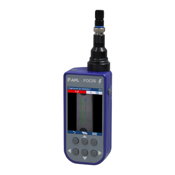
Page 8: Focis Lightning Overview
FOCIS Lightning Overview Controls, Display, Interfaces Contr 1 Power button - 2 Image Capture button - 3 F1 soft button (typically Back function) 4 F2 soft button (typically Select function) 5 Navigation and Edit functional buttons Display (2-inch Color LCD [320 x 240]) -
Page 9: Getting Started
Power-Down Press and hold the Power button until display turns off. • Configure FOCIS Lightning to Auto-Off From the Main Menu -> Settings, select • Display & Power Save option. Select desired power save option: 2 min, 5 min, 10 min, Never. -
Page 10: Mpo Live Image Mode Overview
Getting Started MPO Live Image Mode Overview FOCIS Lightning powers-up in the Live Image mode screen. Note: Users can always display the Live Image screen (from any other mode/screen) by pressing the Capture button once or by pressing the Back button enough times. -
Page 11: Buttons Functionality
– Image is captured when auto focus completes – Image is analyzed if Pass/Fail set to On – FOCIS Lightning transitions to Captured Image mode When the Auto Focus option is disabled in the Setting screen and Capture button is pressed: •... -
Page 12: Understanding Mpo Connector Key Orientation Settings
This setting should be defined in the in Live Image mode prior to • the Image Capture. Understanding Fiber Numbering After The Image Capture After the fiber end-face image is captured, FOCIS Lightning transitions to the Captured Image mode displaying inspection results. Default display: •... -
Page 13: Capture Button Operation
2. Plug FOCIS Lightning adapter tip into the MPO alignment sleeve. 3. Turn on FOCIS Lightning (press the Power button on top). 4. The full MPO end-face in “1+2” view mode will be displayed on the FOCIS Lightning display In less than two seconds. 5. Press the Capture button... -
Page 14: Captured Mpo Image - Overview Page
Getting Started Captured MPO Image - Overview Page Once an end-face image has been captured and analyzed, the full MPO end-face image with Pass/Fail overlay (if enabled) will be displayed in the Captured Image mode. # Description 1 Screen title: displays file name (e.g. COO1-003) if saved image is shown or ‘Captured @ hh:mm:ss’ if unsaved image is shown. -
Page 15: Detailed View Of The Currently Selected Fiber
Getting Started Detailed View of the Currently Selected Fiber # Description 1 Screen title: displays file name (e.g. COO1-003) if saved image is shown or ‘Captured @ hh:mm:ss’ if unsaved image is shown. 2 Fiber Analysis status (Pass or Fail) and Number of the currently displayed fiber. 3 Image Details/Analysis Details page indicator: blue highlight ( ) indicates the currently displayed view/page. -
Page 16: Pass/Fail Analysis Details Page
Getting Started Pass/Fail Analysis Details Page # Description 1 Screen Title: displays File Name (e.g. COO1-003) if saved image is shown or Captured @ hh:mm:ss if unsaved image is shown. 2 Fiber Analysis status (Pass or Fail): shown only if the Pass/Fail option is enabled in Settings. 3 Image Details/Analysis Details pages indicator: blue highlight ( ) indicates current page. -
Page 17: Image Information Page
Getting Started Image Information Page # Description 1 Screen title: displays file name as follows: <Cable>-<Connector> (e.g. COO1-003) if saved image is shown. • ‘Captured @ hh:mm:ss’ if unsaved image is shown. • 2 Fiber Analysis status (Pass or Fail): shown only if the Pass/Fail option is enabled in Settings. 3 Number of the currently selected fiber. -
Page 18: Main Menu And Settings
Main Menu and Settings Main Menu Overview Main Menu The Main Menu is accessed from Live Image mode by pressing the Menu button. Main Menu is used to select user preferences, perform general settings, manage saved test results, and perform other non- test functions. -
Page 19: Capture Settings
Main Menu and Settings Capture Settings To Enable Auto Focus 1 From the Main Menu, select Settings > Capture > Auto Focus to enable or disable the auto-focus option as needed. • To Configure Auto-Save and Auto-Send 2 Highlight and Select Auto-Send. Use to disable auto-send, enable on 1st Capture Key, or enable on 2nd Capture Key. -
Page 20: Pass/Fail Analysis
Main Menu and Settings Pass/Fail Analysis IEC Pass/Fail Analysis IEC 61300-3-35 defines connector inspection pass/fail criteria. Pass/Fail criteria depends on: Passing Defect Fiber type (SMF or MMF). • Failing Connector end face regions: • Defect – A region: Core Core –... -
Page 21: Setting Pass/Fail Criteria
Main Menu and Settings Setting Pass/Fail Criteria Pass/Fail menu is accessed from the Live Image mode > Main Menu > Settings. Enable/disable Auto Analysis Highlight Auto Analysis • Press Select to enable/disable Pass/Fail analysis. • Change Rule: Highlight Change Rule •... - Page 22 Main Menu and Settings Setting Pass/Fail Criteria Edit User Rule: Highlight the Change Rule option • Press Select or Right arrow button to display a list of Rules sub-screen • Highlight the User Rules group. • Press Select to display a list of User Rules •...
-
Page 23: Connector Settings
Connector Settings MPO Connector Fiber Configurations Support FOCIS Lightning supports all fiber configurations of MPO-12 up to two rows, with “base 8”, “base 10”, and “base 12” fiber configurations per row as well as other MPO options. Note that solid circle is “dark” or an unused fiber, and open circle is an active or used fiber and will be analyzed by FOCIS Lightning. -
Page 24: To Configure Mpo Connector
Main Menu and Settings To Configure MPO Connector Note: It is important to set the correct MPO fiber configuration prior to inspection! If the MPO connector setting is not configured correctly, the auto-analysis results will likely show “false negatives” and possibly “false positives”. To Configure MPO Connector From the Main Menu >... -
Page 25: Configuring Bluetooth
Main Menu and Settings Configuring Bluetooth See section “Sharing Captured Test Results” on page 29. Display & Power Save Settings From the Main Menu > Settings, highlight the Display & Power Save option, press Select. From the displayed menu, you may perform the following settings: Highlight and select the Auto Off option •... -
Page 26: Saving Captured Images
Saving Captured Images Saving to the Current Folder While in the Captured Image mode, press the Menu button to • display the Save/Send screen. Highlight Save and press Select button to save image and results • to the current folder. Saving to a Newly Created Folder New Job, Cable End, Cable, or Connector names/numbers are created by editing an existing file name. -
Page 27: Viewing Saved Results (Results Manager)
Viewing Saved Results (Results Manager) Opening Image Files - Reviewing Saved Results The Results Manager is accessed from the Live Image mode > Main Menu. From the Main Menu, use Up/Down arrows to navigate and highlight the Results Manager • –... -
Page 28: Using Focis Lightning With Focis Flex App
Using FOCIS Lightning with FOCIS Flex App Download FOCIS Flex App from Google Play or Apple App Store to your smart device. • Pair FOCIS Lightning to your smart device. • In smart device Bluetooth Settings: Enable Bluetooth and make your device visible. -
Page 29: Sharing Captured Test Results
Sharing Captured Test Results Sending Captured Results to FlexScan Automatically sending results to FlexScan Note: Auto Send option cannot be enabled unless FOCIS Lightning is paired to another Bluetooth device. Configuring Bluetooth On FlexScan Configure FlexScan for pairing: • – Select Settings > Bluetooth. -
Page 30: Wifi-Based Inspection File Access On Focis Lightning
On the linking device: Ensure device to be linked (PC, tablet, smart phone) is on and WiFi is enabled • In the WiFi settings control panel of the linking device, locate FOCIS Lightning device, select, and enter • password ‘1234567890’... - Page 31 WiFi-based Inspection File Access on FOCIS Lightning To download and view saved results: Tap/click on ‘RESULTS’ folder • Tap/click on one of the JOB folders , then an ENDx-ENDy folder , then a connector folder •...
- Page 32 WiFi-based Inspection File Access on FOCIS Lightning Tap/click on one of the connector .JPG or .GIF files (for example) • Tap/click the ‘Download’ button to download and save file • Select location to save selected file (if requested) • Repeat as necessary •...
- Page 33 Test & Inspection Thank you for choosing AFL Test & Inspection! www.AFLglobal.com or (800) 321-5298, (603) 528-7780...
Need help?
Do you have a question about the FOCIS and is the answer not in the manual?
Questions and answers