Advertisement
Quick Links
OPM — OLS — Optical Loss Test Kits
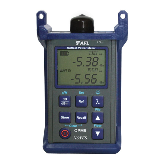
OPM Series Optical Power Meters
OPM5 New Feature
File Management system allows simple organization of power or insertion loss
measurements into multiple files. Using the supplied Test Results Management - TRM
software and USB connection, test records are transferred to a PC for analyzing,
generating professional test reports, and printing.
OPM
Saved
Data
TRM archiving and reporting capabilities take your OPM5 to a new level.
•
Simple USB transfer of saved files (cable supplied)
•
View test results
•
Save test results on your PC / Network
•
Organize standard loss test data into bi-directional loss test data
•
Create Professional Reports for your customers
•
Add link length to loss data and select standards rules to generate Network
Certification Reports for your customers.
For more information, refer to the TRM software User's Guide (available on supplied CD
and www.AFLtele.com/go/Software).
www.AFLtele.com /1.800.321.5298 /1.603.528.7780
Quick Reference Guide
USB
TRM
Laptop/
PC
Professional
Reports
Advertisement

Subscribe to Our Youtube Channel
Related Manuals for AFL OPM Series


Summary of Contents for AFL OPM Series
- Page 1 OPM — OLS — Optical Loss Test Kits Quick Reference Guide OPM Series Optical Power Meters OPM5 New Feature File Management system allows simple organization of power or insertion loss measurements into multiple files. Using the supplied Test Results Management - TRM software and USB connection, test records are transferred to a PC for analyzing, generating professional test reports, and printing.
- Page 2 OPM Series Function Keys Dual Function Keys Legend Secondary function of a key Press and hold to activate Press and release to activate Primary function of a key Power key Provides two functions: • Press to turn On/Off (OPM turns off after five minutes of inactivity).
- Page 3 OPM Series Function Keys dB/dBm/µW key Provides two functions: • Press to toggle test readings between insertion loss in [dB] and power in [dBm]. • Press and hold to view power in [µW]. Ref/Set key Provides two functions: •...
- Page 4 OLS Series Light Sources Dual Function Keys Legend Press and hold to activate Secondary function of a key Press and release to activate Primary function of a key Keys and Indicators common for all models Power key - Press and hold until all indicators light up to turn OLS On/Off. External Power indicator - Lights up, whether the unit is on or off, when the correct AC power adapter is connected Low Battery indicator - Lights up when a Low Battery condition exists;...
- Page 5 OLS2-Dual Laser Source Keys and Indicators Wavelengths select key • Wave ID mode - selects SM single or dual Wave ID wavelengths • CW or Tone mode - selects single wavelength Active Output indicators - will be illuminated when the corresponding output port is ON 1310nm 1550nm Mode key - Press to select operating mode (Wave ID, CW, Tone)
- Page 6 OLS4 Integrated LED & Laser Source Keys and Indicators 1310nm Single-mode Wavelengths/CW select key 1550nm • Press to select single or dual Wave ID wavelength(s) • Press and hold to switch to the CW mode at the current wavelength, then press the key to select a single wavelength Active Output indicators - Light up when the corresponding output port is ON 1310nm...
- Page 7 Measuring Optical Power with OPM meter It is important to keep all optical connections and surfaces clean to ensure accurate measurements and operation. Always clean all test jumpers before conducting tests. Turn on OPM (optical power meter). Select the appropriate fiber optic test jumper. The fiber type of this jumper must be the same as the fiber type normally connected to the output being measured.
- Page 8 Testing Multimode or Single-mode Links Step I - Set the Reference (One Jumper Method) Turn on the OPM and OLS. Allow OLS to stabilize (minimum of 2 minutes). If not using WAVE ID feature, set both instruments to the desired wavelength. Select transmit and receive jumpers (fiber type must match link to be tested).
- Page 9 Testing Multimode or Single-mode Links Step II - Verify Test Jumpers Disconnect the transmit jumper from the OPM. Do not disturb the transmit jumper at the OLS end! If needed, change OPM adapter cap to match receive jumper connector. Clean both ends of the receive jumper! Connect the receive jumper to the OPM.
- Page 10 Repeat steps 17-19 for all links to be tested at the current wavelength. Patch panel Patch panel Receive jumper Transmit jumper Link under test Mandrel wrap - MM (shown), or 30 mm loop - SM 2 dB www.AFLtele.com /1.800.321.5298 /1.603.528.7780 © 2010 AFL Telecommunications, all rights reserved. OLTK-00-1ENG Revision 1A, 2010-06-29...
Need help?
Do you have a question about the OPM Series and is the answer not in the manual?
Questions and answers