Advertisement
Table of Contents
- 1 ROGUE Cb1 Device Hardware Overview
- 2 Battery Charging and Operation - ROGUE Cb1 Device
- 3 ROGUE Cb1 Device Touch Screen Display Features
- 4 Installing a Module into ROGUE Cb1 Device
- 5 ROGUE Ib1 Device Hardware Overview
- 6 ROGUE Ib1 Device Battery Charging and Operation
- 7 Installing a Module into ROGUE Cb1 Device
- 8 ROGUE Ib1 Device Touch Screen Display Features
- Download this manual
ROGUE
For best operation, please update all software upon receipt of equipment.
For cB1 units, use the "Check for Updates" function in your smart device app
•
(i.e. TURBO or Linkmap).
For iB1 units, go to the "AFL store" found on the main screen.
•
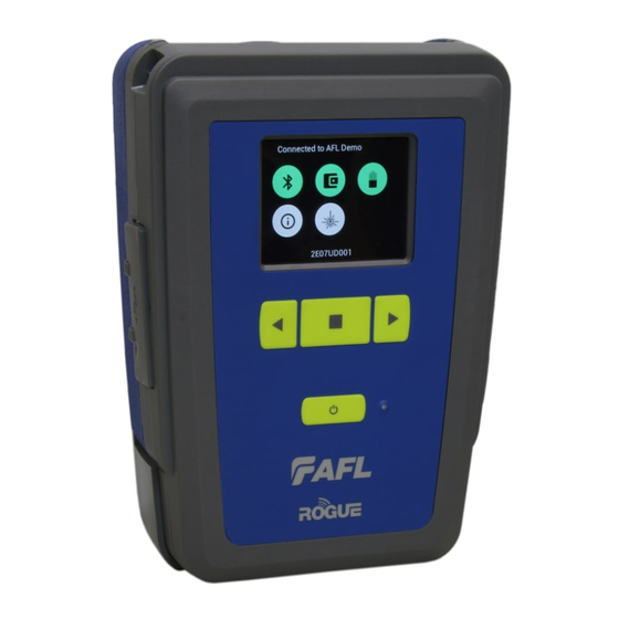
ROGUE cB1 Device Hardware Overview
1
2
3
4
# Feature
1 Strap Eyelet
2 Mini-USB
Function Port
3 USB Host Port
4 Key Slot
5 Touch Screen
Display
6 Function Buttons Used to perform specific tasks. The functionality of these
7 Power Button
Device Quick Reference Guide
®
5
6
7
Description
Used to attach an adjustable carry strap.
May be used for remote control of the device.
Allows connection to USB devices.
Used to mount a Kickstand accessory on the ROGUE cB1.
Contains on-screen controls and menus; allows to select
parameters/functions and control the operation of the cB1.
buttons depends on the active test mode/screen.
Press and hold (~2 seconds) to turn power on or off.
8
13
1
Test & Inspection
9
10
11
12
Advertisement
Table of Contents

Subscribe to Our Youtube Channel
Related Manuals for AFL ROGUE cB1


Summary of Contents for AFL ROGUE cB1
- Page 1 For cB1 units, use the “Check for Updates” function in your smart device app • (i.e. TURBO or Linkmap). For iB1 units, go to the “AFL store” found on the main screen. • ROGUE cB1 Device Hardware Overview # Feature...
- Page 2 13 AC/Charger Port This is an interface for the AC power adapter/charger. Battery Charging and Operation - ROGUE cB1 Device ® ROGUE cB1 device can simultaneously operate and charge the internal battery while connected to the provided AC adapter/charger. To connect the AC adapter/charger: Plug the AC adapter/charger into a •...
- Page 3 Green = >50% White = Between 20% and 50% Red = <20% ROGUE cB1 Information - Pressing this icon provides options to display the following information: Module Version (if installed), cB1 Version, Legal Information. VFL port - Only present if the installed Module has a VFL port.
- Page 4 Installing a Module into ROGUE cB1 Device ® 1. Starting from the cB1 top, align bottom of the Module guiding tracks A with top of the cB1 guiding tracks B . 2. Slide the Module into the cB1 base. 3. Make sure that Module is completely inserted in the Module Slot. 4.
- Page 5 Press and hold (~2 seconds) to turn power on or off. 7 AC/Charger When ON, indicates that an AC adapter is connected to Indicator the ROGUE cB1 device: light - rechargeable battery is Green charging; light - rechargeable battery is fully charged.
- Page 6 # Feature Description 9 Slot for Module This slot accepts one of the ROGUE Modules. 10 Module Interface This connector interfaces with a test module providing Connector power and passing control and data signals between the iB1 and module. 11 Battery Holds removable/rechargeable Li-ion battery.
- Page 7 Installing a Module into ROGUE cB1 Device ® 1. Starting from the iB1 top, align bottom of the Module guiding tracks A with top of the iB1 guiding tracks B . 2. Slide the Module into the iB1 base. 3. Make sure that Module is completely inserted in the Module Slot. 4.
- Page 8 VFL port - Only present if the installed Module has a VFL port. Color code: White = VFL port is Off. Green = VFL port is On. Flashing Green = VFL is On/Pulse. For detailed operating instructions on all ROGUE products, visit www.AFLglobal.com ©2017 AFL, all rights reserved. RG1-QRG-1ENG Revision AB, 2017-04-17...
Need help?
Do you have a question about the ROGUE cB1 and is the answer not in the manual?
Questions and answers