
Related Manuals for AFL FOCIS WiFi2


Summary of Contents for AFL FOCIS WiFi2
- Page 1 Test & Inspection FOCIS WiFi2 Fiber Optic Connector Inspection System User Guide www.AFLglobal.com or (800) 321-5298, (603) 528-7780...
-
Page 2: Table Of Contents
Downloading FOCIS WiFi2 App ........ - Page 3 Sharing Captured Test Results ........34 Inspecting Fibers with FOCIS WiFi2 Solution ..... 35...
-
Page 4: Safety Information
IMPORTANT! Proper care in handling should be taken when using any precision optical test equipment. Scratched or contaminated optical connectors can impact the performance of the instrument. NOTE! FOCIS WiFi2 contains no user serviceable parts. This instrument must be returned to AFL or authorized agents for repair. -
Page 5: Standards Compliance Information
The term “IC:” before the certi cation/registration number does not imply that Industry Canada approved the equipment. Le FOCIS WiFi2 d’AFL est conforme à la norme d’Industrie Canada RSS 247. Voir RSS GEN 7.1.5. Le terme “IC:” avant le numéro de certi cation/enregistrement signi e seulement que l’enregistrement a été... -
Page 6: General Information
APC polished end-faces. FOCIS WiFi2 App By pairing the FOCIS WiFi2 inspection probe with the FOCIS WiFi2 App, users are enabled to control their test hardware directly from their Android or iOS smart devices. FOCIS WiFi2 App is available via Google play store or Apple Store. -
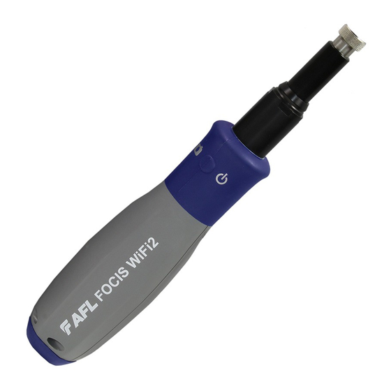
Page 7: Focis Wifi2 Probe Overview
4. Multifunctional button has several multiplexed functions. See “Multifunctional Button Operation” on page 8. 5. Multifunctional LED indicator represents various states of the FOCIS WiFi2. See “Multifunctional LED Indicator States” on page 8. 6. 5 VDC input jack. 7. Charging indicator. -
Page 8: Multifunctional Button Operation
In the Captured Image mode, press the Multifunctional • button to return to the Live Image mode. Multifunctional LED Indicator States Multifunctional LED indicator represents various states of the FOCIS WiFi2 as follows: Action State LED Color/Behavior FOCIS WiFi2 power On... -
Page 9: Battery Charging And Operation
Configuring FOCIS WiFi2 Probe to Auto-Off FOCIS WiFi2 probe Power Save options are controlled by iOS & Android Apps. The following instructions assume that FOCIS WiFi2 probe is connected to a smart device, which operates in the FOCIS WiFi2 App. -
Page 10: Properly Installing And Removing Adapter Tips
FOCIS WiFi2 Probe Overview Properly Installing and Removing Adapter Tips FOCIS WiFi2 is available with the following adapter tips: Connector UPC Connectors APC Connectors Ferrule Bulkhead Ferrule Bulkhead FFLX-01-U25 FFLX-01-SC FFLX-01-A25 FFLX-01-ASC FFLX-01-U25 FFLX-01-FC FFLX-01-A25 FFLX-01-AFC FFLX-01-U125 FFLX-01-LC FFLX-01-A125 FFLX-01-ALC2... -
Page 11: Focis Wifi2 App Overview
On FOCIS WiFi2 probe: Press and release the button to power On. • LED status indicator will display Flashing Blue light indicating that FOCIS WiFi2 is in “WiFi Beacon • Mode” – ready to connect to your smart device. On your Smart Device: Navigate to Settings. -
Page 12: Mobile Device Screen Format
Note: ‘Screen Rotation’ feature needs to be enabled in the mobile device Settings menu. Supported Touch Screen Gestures The FOCIS WiFi2 App display is controlled from the touch screen of the mobile device using a supported set of gestures Touch Gesture... -
Page 13: Live Image Mode
Live Image Mode Live Image Screen Features FOCIS WiFi2 App starts in the Live Image mode, which enables the user to view live images of a ber end-face and perform visual inspection of the displayed ber end-face image on a mobile device. -
Page 14: Main Menu
Main Menu Main Menu Overview The Main Menu is accessed from Live Image mode by tapping the Menu on-screen button. Main Menu contains various Settings that are used to select user preferences, perform general settings, manage saved test results, and perform other non-test functions. The Main Menu screen contains the following controls: (On/Off) -Tapping this control enables/disables the selected Setting. -
Page 15: Pass/Fail
Beeper 3. Tap the control to enable/disable a sound signal that indicates Pass/Fail Analysis results. When enabled, FOCIS WiFi2 will produce High tone beep for Passed results and Low tone beep for Failed or No Fiber results. Auto-Power Off 4. Tap on the Right arrow to display a pop-up menu. -
Page 16: Report Settings
FOCIS WiFi2 App User Interface Overview Main Menu Report Settings 1. Con gure reports by adding various data: Customer, Company, Location, Operator, and Comments. These report settings will be applied to all saved result. Result Manager 2. Tap on the Right arrow to display the Result Manager, which allows the user to manage stored results. -
Page 17: Captured Image Mode
Captured Image Mode Captured Image Views Once a ber end-face image has been captured and analyzed (if enabled), inspection test results will be displayed in the Captured Image screen. Tapping on the displayed ber end-face image allows the user to switch the display modes sequentially, as follows: 1. -
Page 18: Fiber Image View
Captured Image Mode Fiber Image View 1. Screen title: Indicates date and time of the test - [Captured @ hh:mm:ss]. 2. Pass/Fail Analysis indication: Shown only if Pass/Fail Analysis option is enabled in the Main Menu. Depending on performed analysis, this eld will display: for Passing ber, for Failing ber, if No Fiber detected during Pass/Fail Analysis. -
Page 19: Pass/Fail Results Table View
Captured Image Mode Pass/Fail Results Table View 1. Screen title: Indicates date and time of the test - [Captured @ hh:mm:ss]. 2. Pass/Fail Analysis indication: Shown only if Pass/Fail Analysis option is enabled in the Main Menu. Depending on performed analysis, this eld will display: for Passing ber, for Failing ber, if No Fiber detected during Pass/Fail Analysis. -
Page 20: Image Information View
Captured Image Mode Image Information View 1. Screen title: Indicates date and time of the test - [Captured @ hh:mm:ss]. 2. Pass/Fail Analysis indication: shown only if Pass/Fail Analysis option is enabled in the Main Menu. Depending on performed analysis, this eld will display: for Passing ber, for Failing ber, if No Fiber detected during Pass/Fail Analysis. -
Page 21: Pass/Fail Criteria
Pass/Fail Criteria Pass/Fail Screen Features Con guring Pass/Fail criteria is done in the Pass/Fail screen, which is accessed from Live Image mode > Main Menu screen. 1. From the Live Image screen, tap Menu 2. In the Main Menu, tap on the Right arrow next to the Pass/Fail option to display a sub-screen that allows the user to enable, select and con gure Rules for Pass/Fail Analysis. -
Page 22: Iec, Ipc, At&T Pass/Fail Analysis
Pass/Fail Criteria IEC, IPC, AT&T Pass/Fail Analysis IEC 61300-3-35 de nes connector inspection Pass/Fail criteria. Pass/Fail criteria depends on: Passing Defect Fiber type (SMF or MMF) • Failing Connector end-face Zones • Defect – A: Core Core – B: Cladding –... -
Page 23: Configuring Pass/Fail Criteria
Pass/Fail Criteria Configuring Pass/Fail Criteria Enable/Disable Pass/Fail Analysis Access the Main Menu screen. • Tap the control to enable/disable Pass/Fail Analysis. • Select Rule Tap on the Right arrow to display a list of available Rules • (preset IEC, IPC, AT&T and user-set rules). Tap the desired Rule (shown as Folder image) to select. -
Page 24: Edit User Rule
Pass/Fail Criteria Configuring Pass/Fail Criteria Edit User Rule: To edit User Rule double tap on the desired User Rule or similar Standard Rule (any • available rule). Settings for Zone, Scratches and Defects will be shown. • Tap on desired eld to view and edit settings. •... - Page 25 Pass/Fail Criteria Configuring Pass/Fail Criteria While in any of Settings screen, Zone/Scratches/Defects: • – Tap the On/Off - control to enable/disable the desired Rule parameter. – Once enabled, tap on the desired eld to edit the parameter value. – Using on screen Editor, change the selected value as needed. –...
-
Page 26: Result Manager
Result Manager Result Manager Screen To access the Result Manager From the Live Image mode, tap Menu to display the Main Menu. • Tap on the Right arrow next to the Result Manager option. • Result Manager screen displays saved test results organized into Jobs, Cables, Fibers. •... -
Page 27: Creating A New Job/Cable Folder
Result Manager Creating a New Job/Cable Folder 1. In the Result Manager screen, double tap Add in the Jobs eld. 2. In the Job Editor screen, note that new Job is created with a default name format: Job YYYMMDD 3. Edit the default Job name as needed, then tap Accept or Done 4. -
Page 28: Renaming A Job/Cable/Fiber
Result Manager Renaming a Job/Cable/Fiber To Rename Saved Test Results 1. Navigate to the desired item, Job/Cable/Fiber; tap to select. 2. Tap on the Share button. 3. Tap RENAME. 4. Using the displayed on screen Editor, make changes as needed. 5. -
Page 29: Saving Test Results
Result Manager Saving Test Results Saving Test Results for the First Time If test results are saved for the rst time and no Job/Cable folder previously created in the Result Manager, then default settings for Job/Scope End/Far End/Cable/Fiber will be used, where: 1. -
Page 30: Saving Test Results To A New Job/Cable Folder
Result Manager Saving Test Results to a New Job/Cable Folder To save test results to a new Job/Cable folder 1. Capture an image. Once the captured image is displayed, tap on the Information tab. 2. In the Information Details screen, tap on the Right Arrow in the Job line. -
Page 31: Saving Test Results To An Existing Job/Cable Folder
Result Manager Saving Test Results to an Existing Job/Cable Folder To save test results to an existing Job/Cable folder 1. Capture an image. Once the captured image is displayed, tap on the Information tab. 2. In the Information Details screen, look at the Job Folder name - this is the current folder where the test result will be saved. -
Page 32: Result Manager Functionality
Result Manager Result Manager Functionality To Select a Single Item - Job/Cable/Fiber Tap on the desired Job/Cable/Fiber icon to select it. If a Job (Cable) folder contains Cables (Fibers) • then tapping on that folder will expend it to show contents. Note that color of the selected item changes from Yellow (folder) / White ( ber) to Blue. -
Page 33: To Delete Saved Test Results
Result Manager Result Manager Functionality To Delete Saved Test Results 1. Select a single item or multiple items for deletion. – To select a single item, navigate to the desired item (Job/Cable/Fiber), and then tap on it to select. – To select multiple items, tap on the Group button to enable multi-select functionality, and then tap on as many items as needed to multi-select. -
Page 34: Sharing Captured Test Results
2. Tap on the Share button. 3. From the displayed pop-up menu, select SEND TO. 4. FOCIS WiFi2 will generate zipped le with Job-Cable-Fiber path. 5. From the displayed list, select the desired transferring option. Follow on-screen instructions. -
Page 35: Inspecting Fibers With Focis Wifi2 Solution
2. Connect FOCIS WiFi2 probe to the FOCIS WiFi2 App installed on your mobile device. 3. Insert the ber under test into adapter tip. 4. On your FOCIS WiFi2 App, you should see Live video of the ber being inspected. You may perform visual inspection of the displayed ber end-face image. - Page 36 Test & Inspection Thank you for choosing AFL Test & Inspection! www.AFLglobal.com or (800) 321-5298, (603) 528-7780...
Need help?
Do you have a question about the FOCIS WiFi2 and is the answer not in the manual?
Questions and answers