Table of Contents
Advertisement
Advertisement
Table of Contents

Related Manuals for AFL Noyes OFI


Summary of Contents for AFL Noyes OFI
- Page 1 Artisan Technology Group is your source for quality new and certified-used/pre-owned equipment SERVICE CENTER REPAIRS WE BUY USED EQUIPMENT • FAST SHIPPING AND DELIVERY Experienced engineers and technicians on staff Sell your excess, underutilized, and idle used equipment at our full-service, in-house repair center We also offer credit for buy-backs and trade-ins •...
- Page 2 OFI Optical Fiber Identifier User’s Guide Artisan Technology Group - Quality Instrumentation ... Guaranteed | (888) 88-SOURCE | www.artisantg.com...
- Page 3 Artisan Technology Group - Quality Instrumentation ... Guaranteed | (888) 88-SOURCE | www.artisantg.com...
- Page 4 OFI Optical Fiber Identifier User’s Guide © 2002-2008, AFL Telecommunications, all rights reserved. OFI1-11-1000 Revision A, 05.02.08 Specifications are subject to change without notice. Artisan Technology Group - Quality Instrumentation ... Guaranteed | (888) 88-SOURCE | www.artisantg.com...
- Page 5 Exclusions of the equipment. The warranty on your equipment shall not apply AFL Telecommunications to defects resulting from the following: Noyes • Unauthorized repair or modification 16 Eastgate Park Road Belmont, NH 03220 •...
-
Page 6: Table Of Contents
Contents Safety Important Safety Information ........... iv Section 1: General Information Introduction ..............1 Contacting Noyes Customer Service ......... 1 Unpacking and Inspection ..........2 Feature Overview ............2 Section 2: Functional Description OFI 200 Model Features ..........4 Front Panel Indicators ..........6 OFI 400 Model Features .......... - Page 7 Identifying Tone with OFI 200 Model ......18 Testing 250µm/900µm Coated Fibers with OFI 200 ..20 Testing 250µm/900µm Coated Fibers with OFI 400 ..22 Testing Ribbon Fibers (OFI 200/ OFI 400) ......23 Testing 2mm/3mm Jacketed Fibers with OFI 200 ..... 24 Testing 2mm/3mm Jacketed Fibers with OFI 400 .....
- Page 8 OFI 400 Specifications ............ 36 Detectable signal range ..........36 Optical Specifications ..........37 General Specifications ..........38 List of Figures Figure 2-1: OFI 200 Assembly ........5 Figure 2-2: OFI 200 Front Panel Indicators ....7 Figure 2-3: OFI 400 Assembly ........9 Figure 2-4: OFI 400 Keys and Indicators ......
-
Page 9: Safety
Safety Important Safety Information CAUTION! To avoid serious eye injury, never look directly into the optical outputs of fiber optic network equipment, test equipment, patch cords, or test jumpers. Always assume that optical outputs are on. NOTICE! Noyes Optical Fiber Identifiers contain no user serviceable parts. Except for changing batteries, these units must be returned to Noyes or authorized agents for repair and calibration. -
Page 10: Section 1: General Information
Section 1: General Information Introduction The purpose of this User’s Guide is to explain how to use and maintain Noyes test equipment. Please check our web site at www.AFLtele.com (click on Products > Noyes Test & Inspection) for updates to this manual, software updates, and additional application information. If you have any questions about your instruments and recommended accessories, or if you need technical or sales support, please contact Noyes Customer Service. -
Page 11: Unpacking And Inspection
Unpacking and Inspection OFI Optical Fiber Identifier has been carefully packed in accordance with standard shipping procedures. Examine your OFI for damage that may have occurred during shipment. If you find any damage, please contact Noyes. Feature Overview Noyes Optical Fiber Identifiers are rugged, handheld, and easy-to-use fiber optic test instruments for the installation and maintenance of fiber optic networks. - Page 12 identification, 2 kHz [TONE] signal detection, audible indication when the [TONE] signal is detected, and low battery indication. The OFI 400 model is the next generation of Noyes Optical Fiber Identifiers. It has all the features of the OFI 200 model plus an easy-to-read LCD display with Backlight, multiple [TONE] signal detection (270 Hz, 330 Hz, 1000 Hz, or 2000 Hz), power saving feature, and [Set Reference] feature.
-
Page 13: Section 2: Functional Description
Section 2: Functional Description OFI 200 Model Features The OFI 200 is powered by a standard 9 volt alkaline battery that typically provides over 10,000 operations. Power is controlled by the clamping trigger located on backside of the instrument. The OFI 200 operates only when the trigger is engaged. This ensures extended battery life and minimizes ambient light influence. -
Page 14: Figure 2-1: Ofi 200 Assembly
TRAFFIC NO SIGNAL TONE LOW BATT OFI 200 Figure 2-1: OFI 200 Assembly Artisan Technology Group - Quality Instrumentation ... Guaranteed | (888) 88-SOURCE | www.artisantg.com... -
Page 15: Front Panel Indicators
Front Panel Indicators Figure 2-2 illustrates the OFI 200 front panel indicators described below. 1 [DIRECTION OF TRAFFIC] indicators - [Left] and [Right] arrows identify the direction of the detected [TRAFFIC] signal. 2 [TRAFFIC] indicator - Illuminates when a [TRAFFIC] signal is present regardless of the transmission rate. -
Page 16: Figure 2-2: Ofi 200 Front Panel Indicators
TRAFFIC NO SIGNAL TONE LOW BATT OFI-200 Figure 2-2: OFI 200 Front Panel Indicators Artisan Technology Group - Quality Instrumentation ... Guaranteed | (888) 88-SOURCE | www.artisantg.com... -
Page 17: Ofi 400 Model Features
OFI 400 Model Features The OFI 400 model is powered by standard 2 x 1.5V alkaline batteries that typically provide over 10,000 operations. Power is controlled either by pressing the [Power] key located on the front panel of the instrument or by pulling the trigger all the way down. To ensure extended battery life, the OFI 400 will turn [Off] after 4 minutes of inactivity. -
Page 18: Figure 2-3: Ofi 400 Assembly
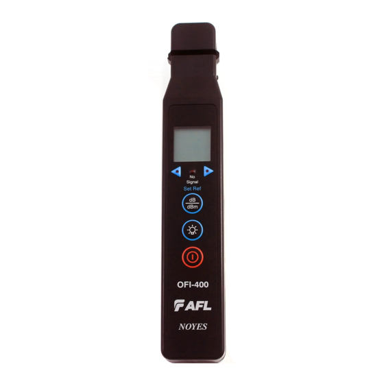
AFL Telecommunications -88.8 8888 SIGNAL Set Ref OFI 400 NOYES Figure 2-3: OFI 400 Assembly Artisan Technology Group - Quality Instrumentation ... Guaranteed | (888) 88-SOURCE | www.artisantg.com... -
Page 19: Front Panel Features
Front Panel Features Figure 2-4 illustrates the OFI 400 front panel keys and indicators described below. 1 Display - Shows core power measurements (absolute - dBm or relative - dB), multiple test tone frequencies - Hz (if present), and low batteries status. 2 [Direction of Traffic] indicators - [Left] and [Right] arrows identify the direction of the detected [TRAFFIC] signal. -
Page 20: Figure 2-4: Ofi 400 Keys And Indicators
• [Press and Hold] the key during power up until the letter [P] is displayed to disable the [Auto Off] feature. Unit will remain [On] until the [Power] key is pressed to turn it [Off]. AFL Telecommunications SIGNAL Set Ref... -
Page 21: Display Readings
Display Readings Figures 2-5 illustrate the OFI 400 display readings described below. [Battery status] indicator - The Battery icon will appear on the display to indicate a “low battery” condition. The discharged 2 x 1.5V alkaline batteries will require replacement. 2 Core power measurements - This field will display core power measurements [dBm or dB]. -
Page 22: Figure 2-5: Ofi 400 Display
-88.8 8888 Figure 2-5: OFI 400 Display Artisan Technology Group - Quality Instrumentation ... Guaranteed | (888) 88-SOURCE | www.artisantg.com... -
Page 23: Section 3: Operating Instructions
Section 3: Operating Instructions Precautions It is important that the precautions given below be followed to ensure operating efficiency and to prevent inducing excessive signal loss during testing. All optical test equipment should be kept free of dirt and other contaminants. The OFI models utilize an optical assembly, which must be kept free of dirt and grease. -
Page 24: Figure 3-1: Shielding The Optical Assembly Area
Caution: Core Power Accuracy is not specified with the OFI 400. Displayed power levels on the OFI 400 should not be used to determine actual signal strength in the optical fiber. Figure 3-1: Shielding the Optical Assembly Area Artisan Technology Group - Quality Instrumentation ... Guaranteed | (888) 88-SOURCE | www.artisantg.com... -
Page 25: Identifying Tone On Fibers
Identifying Tone on Fibers During installations, maintenance, rerouting, or restorations it is often necessary to isolate a specific fiber from a bundle without disrupting service. By simply clamping the OFI 200 or OFI 400 onto a fiber before making any cuts, the identifier will indicate if there is [TRAFFIC], [TONE], or [NO SIGNAL] and display the detected [TRAFFIC] signal direction. - Page 26 5 When a [TONE] signal is detected, the OFI 400 will produce the continuous “beep” signal and show the [TONE] frequency value on the display. Important: The displayed level measurements (dBm) on the OFI 400 are strictly dependent upon the amount of signal striking the photodiodes in the detector head. Light reaching the detector head is dependent on fiber coating color, coating thickness and link under test -88.8...
-
Page 27: Identifying Tone With Ofi 200 Model
varies significantly when testing 250 micron fiber up to 3 mm jacketed fiber. In no situation will the displayed level be an accurate representation of the actual signal strength in the fiber. Under no circumstances should an optical fiber be cut or disconnected based on displayed levels on the OFI 400. - Page 28 Important: Optical Fibers should only be cut or disconnected after the fiber has been positively “toned” using an optical laser source transmitting the 2 kHz [TONE]. link under test Light source OFI 200 Artisan Technology Group - Quality Instrumentation ... Guaranteed | (888) 88-SOURCE | www.artisantg.com...
-
Page 29: Testing 250Μm/900Μm Coated Fibers With Ofi 200
Testing 250µm/900µm Coated Fibers with OFI 200 The following procedure may be used for testing 250 µm or 900 µm coated fibers. Note: It is important to place the plunger in the correct position. Please refer to the illustration to the right. 1 Remove the plunger cover. - Page 30 8 Once the trigger is completely retracted, the OFI 200 will power up and discriminate optical signals transmitted through a single-mode fiber. • If the fiber is carrying service, the [TRAFFIC] indicator will illuminate showing the presence of service and the signal direction. •...
-
Page 31: Testing 250Μm/900Μm Coated Fibers With Ofi 400
Testing 250µm/900µm Coated Fibers with OFI 400 The following procedure may be used for testing 250 µm or 900 µm coated fibers. Note: It is important to place the plunger in the correct position. Please refer to the illustration Plunger cover to the right. -
Page 32: Testing Ribbon Fibers (Ofi 200/ Ofi 400)
9 Once the trigger is completely retracted, the OFI 400 will discriminate optical signals transmitted through a single-mode fiber. • If the fiber is carrying service, the LCD display will show the power readings and indicate the signal direction by illuminating the corresponding [Traffic Direction] indicator. •... -
Page 33: Testing 2Mm/3Mm Jacketed Fibers With Ofi 200
Testing 2mm/3mm Jacketed Fibers with OFI 200 The following procedure may be used for testing 2mm/3mm jacketed fiber cables. Note: It is important to place the plunger in the correct position. Please refer to the illustration to the right. Plunger cover Retaining pins 1 Remove the plunger cover. - Page 34 7 Pull down and hold the trigger to depress the fiber against the optical assembly. 8 Once the trigger is completely retracted, the OFI 200 will power up and discriminate optical signals transmitted through a single-mode fiber. • If the fiber is carrying service, the [TRAFFIC] indicator will illuminate showing the presence of service and the signal direction.
-
Page 35: Testing 2Mm/3Mm Jacketed Fibers With Ofi 400
Testing 2mm/3mm Jacketed Fibers with OFI 400 The following procedure may be used for testing 2mm/3mm jacketed fiber cables. Note: It is important to place the plunger in the correct position. Please refer to the illustration to the right. 1 Remove the plunger cover. 2 Make sure the plunger is oriented Plunger cover as shown in the illustration. - Page 36 7 Gently insert the fiber being tested into the fiber groove at the top of the OFI 400 head (refer to Figure 2-3). 8 Pull down and hold the trigger to depress the fiber against the optical assembly. 9 Once the trigger is completely retracted, the OFI 400 will discriminate optical signals transmitted through a single-mode fiber.
-
Page 37: Measuring Core Power With Ofi 400 Model
Measuring Core Power with OFI 400 Model The following procedure may be used for measuring fiber core power. 1 Turn on the OFI 400 by pressing the [Power] key. 2 Gently insert the fiber to be tested into the fiber groove at the top of the OFI 400 head (refer to Figure 2-3). -
Page 38: Measuring Relative Power With Ofi 400 Model
Measuring Relative Power with OFI 400 Model The following procedure may be used for measuring relative power. 1 Turn on the OFI 400 by pressing the [Power] key. 2 Gently insert the fiber to be tested into the fiber groove at the top of the OFI 400 head (refer to Figure 2-3). -
Page 39: Section 4: Maintenance
Section 4: Maintenance Repair and Calibration Repair of the Noyes test equipment in the field is NOT recommended. Calibration is recommended every 36 months. Noyes Calibration Department is in compliance with ANSI/NCSL Z540-1, ISO 10012-1, MIL STD 45662A, ISO Guide 25 and traceability to the National Institute of Standards and Technology. -
Page 40: Cleaning Optical Assembly
Cleaning Optical Assembly Optical assembly of the OFI Optical Fiber Identifier must be kept free from dirt or other contaminants to ensure operating efficiency and accurate measurements. Note: • For cleaning the OFI optical assembly, use lint-free optical cleaning wipes and 99% IPA (isopropyl alcohol) that has not been contaminated. -
Page 41: Ofi 200 Battery Replacement
OFI 200 Battery Replacement When the [LOW BATT] indicator illuminates on the OFI 200 front panel, the discharged 9V alkaline battery requires replacement. To replace the discharged battery: 1 Remove the retaining screw and slide the battery plate away from the unit. 2 Replace the discharged battery. -
Page 42: Ofi 400 Battery Replacement
OFI 400 Battery Replacement When the - Low Battery indicator appears at the top of the OFI 400 display, the 2 x 1.5V alkaline batteries require replacement. To replace the discharged batteries: 1 Remove the retaining screw and slide the battery plate away from the unit. 2 Replace the discharged batteries. -
Page 43: Section 5: Specifications
1310 nm 0.8 dB (typical) 1550 nm 2.5 dB continued on the next page Specifications are subject to change without notice © 2002-2008, AFL Telecommunications. All rights reserved. Artisan Technology Group - Quality Instrumentation ... Guaranteed | (888) 88-SOURCE | www.artisantg.com... -
Page 44: Optical Specifications
Optical Specifications Detector type InGaAs Specified wavelength of operation 1310 & 1550 nm Fiber stress <100 kPSI max Fiber size 250 µm, 900 µm, 2 mm or 3 mm jacketed & ribbon fiber Tone detection 2000 ±100Hz Measurement time <1.0 second General Specifications Operation temperature 0 to +50°C, 90% RH (Non-condensing) -
Page 45: Ofi 400 Specifications
1310 nm 1.0 dB (typical) 1550 nm 2.8 dB continued on the next page Specifications are subject to change without notice © 2002-2008, AFL Telecommunications. All rights reserved. Artisan Technology Group - Quality Instrumentation ... Guaranteed | (888) 88-SOURCE | www.artisantg.com... -
Page 46: Optical Specifications
Optical Specifications Detector type InGaAs Specified wavelength of operation 1310 & 1550 nm Calibrated size of fiber and wavelength 250 μm (SMF-28) @1550 nm Fiber stress < 100 kPSI max Fiber size 250 µm, 900 µm, 2 mm or 3 mm & ribbon fiber Tone detection 270, 330, 1000, or 2000 Hz (±5%) Traffic/Tone detect range... -
Page 47: General Specifications
[TONE] is a light signal modulated into a nominal 50% duty cycle square wave. Specifications are subject to change without notice © 2002-2008, AFL Telecommunications. All rights reserved. Artisan Technology Group - Quality Instrumentation ... Guaranteed | (888) 88-SOURCE | www.artisantg.com... - Page 48 Thank you for choosing Noyes Test & Inspection 16 Eastgate Park Road Belmont, NH 03220 Phone: 800-321-5298 603-528-7780 Fax: 603-528-2025 www.AFLtele.com > Products > Noyes Test & Inspection Artisan Technology Group - Quality Instrumentation ... Guaranteed | (888) 88-SOURCE | www.artisantg.com...
- Page 49 Artisan Technology Group is your source for quality new and certified-used/pre-owned equipment SERVICE CENTER REPAIRS WE BUY USED EQUIPMENT • FAST SHIPPING AND DELIVERY Experienced engineers and technicians on staff Sell your excess, underutilized, and idle used equipment at our full-service, in-house repair center We also offer credit for buy-backs and trade-ins •...
Need help?
Do you have a question about the Noyes OFI and is the answer not in the manual?
Questions and answers