AFL NOYES OLS Series User Manual
Light sources, optical power meters, and related test kits
Hide thumbs
Also See for NOYES OLS Series:
- User manual (38 pages) ,
- User manual (38 pages) ,
- User manual (38 pages)
Table of Contents

Related Manuals for AFL NOYES OLS Series


Summary of Contents for AFL NOYES OLS Series
- Page 1 OLS Series Light Sources, OPM Series Optical Power Meters, and Related Test Kits User’s Guide © 2004-2009, AFL Telecommunications, all rights reserved. COM4-00-1001 Revision E, 2009-06-16 Specifications are subject to change without notice.
- Page 2 Exclusions of the equipment. The warranty on your equipment shall not apply AFL Telecommunications to defects resulting from the following: Noyes • Unauthorized repair or modification 16 Eastgate Park Road Belmont, NH 03220 •...
-
Page 3: Table Of Contents
Contents Safety Information Important Safety Information ..........III Section 1: General Information Contacting Noyes Customer Service ......... 1 Unpacking and Inspection ..........1 Recommended Accessories ..........2 Section 2: Functional Description OLS1 LED Light Source ........... 3 OPM1 Power Meter ............4 Front Panel Features ........... - Page 4 Section 4: Maintenance Battery Replacement ............14 Cleaning Optical Ports ............. 14 To Clean the OPM1 Optical Port ........15 To Clean the OLS1-1C and OLS1-2C Ports ....15 Repair and Calibration ............. 16 Section 5: Specifications and Accessories OLS1 LED Light Source Specifications ......17 OPM1 Optical Power Meter Specifications ......
-
Page 5: Safety Information
Safety Information Important Safety Information WARNING! Use of controls or adjustments other than those specified herein may result in hazardous radiation exposure. The OLS1 optical light source is a CLASS I LED PRODUCT. WARNING! To avoid the danger of fire and electrical shock: •... - Page 6 WARNING! Use only the specified AC adapter. Use of another type of AC adapter can damage the instrument and create the danger of fire and electrical shock. CAUTION! To avoid serious eye injury, never look directly into the optical outputs of fiber optic network equipment, test equipment, patch cords, or test jumpers.
-
Page 7: Section 1: General Information
Section 1: General Information The purpose of this User’s Guide is to explain how to use and maintain Noyes test equipment. Please check our web site at www.AFLtele.com/go/Noyes for updates to this manual, software updates, and additional application information. If you have any questions about your instruments and recommended accessories, or if you need technical or sales support, please contact Noyes Customer Service. -
Page 8: Recommended Accessories
For cleaning connector end faces on OLS light sources, test jumpers, and in fiber frames or adapters, use optical quality cleaning fluid such as AFL FCC2 connector cleaning fluid and AFL CCT molded cleaning tips. For cleaning OPM1 optical ports and adapter caps, use lint-free optical cleaning wipes such as AFL FiberWipes and optical quality cleaning fluid such as AFL FCC2 connector cleaning fluid (or IPA - Reagent Grade Isopropyl Alcohol 99% or better) and a can of filtered compressed air. -
Page 9: Section 2: Functional Description
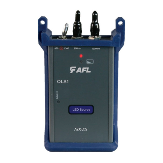
Power port - Interface for an battery condition; battery AC power adapter. replacement is required. LED Source [Power] indicator - Lights up when the correct NOYES A C p o w e r a d a p t e r i s AFL Telecommunications connected. -
Page 10: Opm1 Power Meter
OPM1 Power Meter Front Panel Features Adapter cap Optical input - adapter cap The OPM1 must be equipped mount with an adapter cap. Adapter Accept s N oyes thread- on adapter caps. caps for different connector styles are available from Noyes. NOYES FIBER SYSTEMS Display... -
Page 11: Display Readings
Display Readings [Low battery] indicator [Wavelength] indicator Displays the currently If shown, indicates a low selected test wavelength. battery condition. Replace the battery. 1310 AUTO OFF -20.0 [AUTO OFF] indicator If shown, indicates that the Power reading unit will automatically turn Displays measured power [dBm]. -
Page 12: Section 3: Applications
Section 3: Applications It is important to keep all optical connections and surfaces free from dirt, oils, or other contaminants to ensure proper operation. Always clean all test jumpers before conducting the test procedures outlined in this Guide. Measuring Optical Power Figure 3-1 illustrates the following procedures. - Page 13 Fiber optic equipment Output Input Adapter cap NOYES FIBER SYSTEMS OPTICAL POWER METER 1300 AUTO OFF -20.0 Test jumper OPM 1 Power Figure 3-1: Measuring Optical Power.
-
Page 14: Testing Multimode Links
Testing Multimode Links Step I - Set the Reference (One Jumper Method) Figure 3-2 illustrates the following procedures. 1 Turn on the OPM1 optical power meter and OLS optical light source. Allow the light source to stabilize (minimum of 2 minutes). 2 Set both instruments to the desired test wavelength. - Page 15 current wavelength. Verify Test Jumpers Proceed to Step II - Transmit jumper Mandrel wrap 0 dB OPM1 Figure 3-2: Set the Reference.
-
Page 16: Step Ii - Verify Test Jumpers
Step II - Verify Test Jumpers Figure 3-3 illustrates the following procedures. 10 Disconnect the transmit jumper from the OPM1. Note: Do not disturb the transmit jumper at the OLS end. 11 If necessary, change the OPM1 adapter cap to match the connector on the receive jumper that will be connected to the OPM1. - Page 17 Adapter Transmit jumper Receive jumper Mandrel wrap Do NOT disturb New adapter cap this connection (if necessary) 0.4 dB OPM1 Figure 3-3: Verify Test Jumpers.
-
Page 18: Step Iii - Measure Multimode Link Insertion Loss
Step III - Measure Multimode Link Insertion Loss Figure 3-4 illustrates the following procedures. 17 Connect the free ends of the transmit and receive jumpers to the multimode link under test. Note: Clean jumper end that connects to patch panel prior to every test. 18 Record the displayed power level. - Page 19 Patch panel Patch panel Transmit jumper Receive jumper Mandrel wrap Link under test 2 dB OPM1 Figure 3-4: Measure Multimode Link Insertion Loss.
-
Page 20: Section 4: Maintenance
Section 4: Maintenance Battery Replacement To replace a battery: 1 Remove the protective rubber boot from the instrument. 2 Remove the battery compartment cover located on the back of the instrument. 3 Replace the discharged battery. 4 Replace the battery compartment cover and rubber boot. Cleaning Optical Ports CAUTION! Before conducting the following procedures be sure to have the instruments turned OFF. -
Page 21: To Clean The Opm1 Optical Port
To Clean the OPM1 Optical Port 1 Unscrew the adapter cap from the adapter cap mount. 2 Use lint-free optical cleaning wipes such as AFL FiberWipes and optical quality cleaning fluid such as AFL FCC2 connector cleaning fluid. Note: if using isopropyl alcohol (IPA), be sure to use 99% pure IPA that has not been contaminated. -
Page 22: Repair And Calibration
Repair and Calibration Repair of the Noyes test equipment in the field is NOT recommended. Calibration is recommended every 12 months. Noyes Calibration Department is in compliance with ANSI/NCSL Z540-1, ISO 10012-1, MIL STD 45662A, ISO Guide 25 and traceability to the National Institute of Standards and Technology. -
Page 23: Section 5: Specifications And Accessories
Section 5: Specifications and Accessories OLS1 LED Light Source Specifications Optical Specifications OLS1-1C OLS1-2C Output wavelength 660 nm - red, 850 nm + 35/-40 850 nm + 35/-40 1300 nm +50/-10 Spectral width (FWHM) 30, 40 nm (typ) 40, 120 nm (typ) Output power >-10*, >-20 dBm >-20, >-20 dBm... -
Page 24: Opm1 Optical Power Meter Specifications
OPM1 Optical Power Meter Specifications Optical Specifications OPM1-2C OPM1-3C Calibration wavelengths 850, 1300, 1310, 1550 nm 850, 1300, 1310, 1550 , 1625 nm Detector type Germanium (Ge) InGaAs Measurement range +6 to -60 dBm +6 to -70 dBm Accuracy* ±0.25 dB Measurement units General Specifications Power... -
Page 25: Mandrels For Multimode Transmit Jumpers
Mandrels for Multimode Transmit Jumpers When testing multimode links using an overfilled LED source, always wrap the transmit jumper five (5) times around the proper diameter mandrel. This is specified by TIA/EIA-568-B and will improve insertion loss measurement repeatability and accuracy. Do NOT use mandrels on multimode receive jumpers or single-mode jumpers. - Page 26 Thank you for choosing Noyes Test & Inspection 16 Eastgate Park Road Belmont, NH 03220 9001 Phone: 800-321-5298 603-528-7780 Fax: 603-528-2025 www.AFLtele.com/go/Noyes...
Need help?
Do you have a question about the NOYES OLS Series and is the answer not in the manual?
Questions and answers