
Subscribe to Our Youtube Channel
Related Manuals for AFL Noyes OPM4-3D


Summary of Contents for AFL Noyes OPM4-3D
- Page 1 Noyes OPM 4 OLS 3 OLS 1 Specs Provided by www.AAATesters.com OLS Series Light Sources, OPM Series Optical Power Meters, and Related Test Kits User’s Guide www.AFLglobal.com/go/NOYES or 1-800-321-5298/1-603-528-7780...
- Page 2 Any product that is found defective within the warranty period will, at the discretion of AFL, be repaired or replaced. Warranty will be voided if the product has been repaired or altered by other than an authorized NOYES product repair facility, if the void sticker has been compromised, or which have been subject to misuse, negligence, or accident.
-
Page 3: Table Of Contents
Table of Contents Safety Information .................4 General Information ................5 OPM-Series Optical Power Meters ............6 OPM4 Models ................6 Ports and Display ..............6 Dual Function Keys ...............7 Test Mode: To Set Reference ..........8 Test Mode: To View Reference ..........8 Display Readings - Splash and Auto Off Screen .....8 Display Readings in Test Mode ..........9 OPM5 Models ................10 New Feature ................10... -
Page 4: Safety Information
Safety Information WARNING! Use of controls or adjustments other than those specified herein may result in hazardous radiation exposure. The OLS1 optical light source is a CLASS I LED PRODUCT. The OLS2 optical light source is a registered CLASS I LASER PRODUCT. The OLS4 optical light source is a registered CLASS I LED and LASER PRODUCT. -
Page 5: General Information
An OPM optical port must be equipped with an adapter cap. A variety of adapter caps, connector adapters, and test jumpers with a variety of lengths and connector styles are available from AFL - NOYES. Optical ports and connector end faces must be kept free from dirt or other contaminates to ensure accurate measurements and operation. -
Page 6: Opm-Series Optical Power Meters
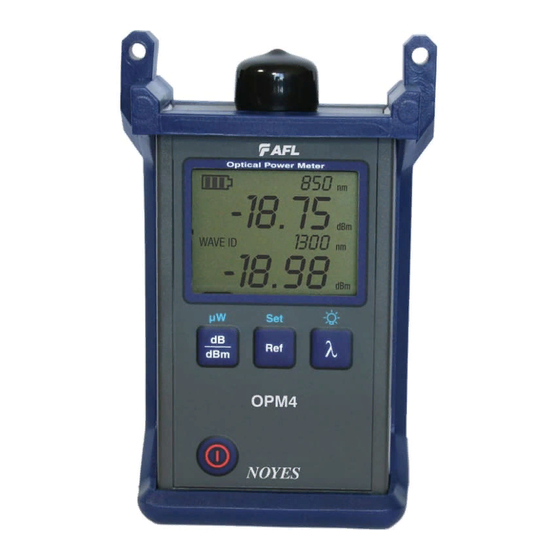
OPM-Series Optical Power Meters OPM4 Models Adapter cap Optical input - adapter cap mount Power Port Optical Power Meter 0000 0.00 µW Display 0000 WAVE ID 0.00 µW µ λ dB/dBm/µW key Wavelength/Backlight OPM4 Set Reference key Power key Ports and Display REF # DESCRIPTION Optical input (adapter cap mount) - accepts NOYES thread-on adapter caps. -
Page 7: Dual Function Keys
OPM4 Models Dual Function Keys Press and hold to activate Secondary function of a key Primary function of a key Press and release to activate Power key Provides two functions: • Press the key to turn the OPM4 on/off. The unit will turn off automatically five minutes after the last key press. -
Page 8: Test Mode: To Set Reference
OPM4 Models Ref/Set key Provides two functions: • To set Reference • To display Reference Test Mode: To Set Reference 1. Set your OPM4 to the desired measurement mode (dB, dBm, µW). 2. To store the currently measured level or multiple levels as the new reference levels, press and hold the Ref key until the label HELD SET is displayed. -
Page 9: Display Readings In Test Mode
OPM4 Models Display Readings in Test Mode 8888 8888 -88.88 -88.88 µW µW dB dBm dB dBm 8888 8888 WAVE ID WAVE ID -88.88 µW dB dBm Single WAVE mode, or Dual WAVE mode, or Tri WAVE mode - second page Tri WAVE mode - first page REF. -
Page 10: Opm5 Models
OPM5 Models Adapter cap Optical input MINI-USB port Optical Power Meter 0000 0.00 µW Display 0000 WAVE ID 0.00 µW Set Reference key µ λ dB/dBm/µW key Wavelength/Backlight File Arrow/File key Store key Store Recall Clear Fiber OPM5 Arrow/Fiber key Power key Recall key New Feature... -
Page 11: Dual Function Keys
OPM5 Models Dual Function Keys Press and hold to activate Secondary function of a key Primary function of a key Press and release to activate Power key Provides two functions: • Press the key to turn the OPM5 on/off. The unit will turn off automatically five minutes after the last key press. -
Page 12: Display Readings - Splash And Auto Off Screen
OPM5 Models dB/dBm/µW key Provides two functions: • Press to toggle test readings between insertion loss in dB and power in dBm A . • Press and hold to view power in µW B . 8888 -88.88 µW dB dBm 8888 WAVE ID -88.88... -
Page 13: Display Readings In Test Mode
OPM5 Models Display Readings in Test Mode 8888 8888 -88.88 -88.88 µW µW dB dBm dB dBm 8888 8888 WAVE ID WAVE ID -88.88 µW dB dBm Single WAVE mode, or Dual WAVE mode, or Tri WAVE mode - second page Tri WAVE mode - first page REF. -
Page 14: File Manager: To Select Current File
OPM5 Models File Manager: To Select Current File 1. Press and hold the Arrow/File key to enter the File Manager - File mode screen. 2. A blinking cursor A to the left of FILE indicates that you are in the File mode. FILE FibS B - File indicator... -
Page 15: Test Mode: To View Reference
PC for analyzing, generating professional test reports, and printing. For more information, refer to the TRM software User’s Guide (available on the supplied CD and from the AFL - NOYES web at www.AFLglobal.com/go/Software). 1. Set your OPM5 to the desired measurement mode (dB, dBm, µW) and wavelengths. -
Page 16: Recall Mode: To View Stored Records
OPM5 Models 5. The current measurements are stored in the next available memory location (next Fiber) of the current File. Recall Mode: To View Stored Records 1. Press and hold the Arrow/File key to enter File mode and select the desired File to view. 2. -
Page 17: To Edit Stored Records
OPM5 Models To Edit Stored Records 1. If needed, press and hold the Arrow/File key to enter File mode and select the desired File. Press the Store key to exit the File mode. 2. Press and hold the arrow key to enter the Fiber mode and select the fiber to edit. •... -
Page 18: Ols-Series Light Sources
OLS-Series Light Sources OLS1-Dual LED Light Source Output port Power port Active Output indicator External Power indicator 850nm 1300nm OLS1 DUAL Optical Light Source 850nm 850/1300/CW 1300nm wavelengths key Power key Low Battery NOYES indicator OLS1-Dual Features 1. Output port - Universal Connector Interface (UCI). Accepts swappable SC connector (ST, FC, and LC connector styles are available). - Page 19 OLS1-Dual LED Light Source Dual 850/ 1300 nm 850 nm 1300 nm Dual 850/ 1300 nm • Press and hold the key to switch to the CW mode at the currently selected wavelength. Note: If the OLS1 operates in the Dual WAVE ID mode, it will switch the output port to the next wavelength in a sequence as follows: Dual 850/1300 nm WAVE ID key Press and hold...
- Page 20 OLS2-Dual Laser Source Output port Power port Active Output indicator External Power indicator 1310nm 1550nm Wave ID OLS2 DUAL Active Mode 2KHz Optical Laser Source 1KHz Indicators 330HZ 270Hz Mode key Mode λ Wavelengths Output Output Adjust keys Adjust Power key Low Battery NOYES indicator...
- Page 21 OLS2-Dual Laser Source WAVE ID Mode (WAVE ID indicator on) Press the l key to select wavelengths in the following sequence: • Dual 1310/ 1550 nm 1310 nm 1550 nm Dual 1310/ 1550 nm Note: When a wavelength is selected, the corresponding Active Output indicator on the front panel is illuminated.
- Page 22 OLS2-Dual Laser Source a) Press and hold either ∆ or ∇ arrow key for ~. 4 seconds to enable the Output Adjust mode. b) When the OLS2-Dual enters the Output Adjust mode, an Active Mode indicator of the currently enabled mode (CW or WAVE ID) turns ON - blinking light, the Output Adjust mode is enabled. The currently selected output can now be adjusted.
-
Page 23: Ols4 Integrated Led And Laser Light Source
OLS4 Integrated LED and Laser Light Source Power port SM output port MM output port MM Active Output SM Active Output indicators indicators 850nm 1300nm 1310nm 1550nm External Power OLS4 indicator Optical Laser Source with Wave ID 850nm 1310nm 1310/1550/CW key 850/1300/CW key 1300nm 1550nm... - Page 24 OLS4 Integrated LED and Laser Light Source 7. Active Output indicators (illuminated when the corresponding output port is ON) - The Active Output indicators light up as follows: Test Mode Active Output indicator status WAVE ID dual Wave corresponding indicators - ON continuous light WAVE ID single Wave corresponding indicator - ON continuous light CW or Tone corresponding indicator - ON blinking light...
-
Page 25: Ols7-3 Triple Wavelength Laser Source
OLS7-3 Triple Wavelength Laser Source Output port Power port 2 Active Output indicators 1310nm 1550nm 1625nm External Power indicator OLS7 Optical Light Source Wave ID Active Mode 2KHz Indicators 1KHz 330HZ 270Hz λ Mode Mode key Wavelengths Power key NOYES Low Battery indicator OLS7-3 Features 1. - Page 26 OLS7-3 Triple Wavelength Laser Source Triple 1310/ 1550/ 1625 nm 1310 nm 1550 nm 1625 nm Dual 1310/ 1550 nm Dual 1550/ 1625 nm Triple 1310/ 1550/ 1625 nm Note: When a wavelength is selected, the corresponding Active Output indicator on the front panel is illuminated.
-
Page 27: Ols7-Ftth Triple Wavelength Laser Source
OLS7-FTTH Triple Wavelength Laser Source Output port Power port 2 Active Output indicators 1310nm 1490nm 1550nm External Power indicator OLS7-FTTH Optical Light Source Wave ID Active Mode 2KHz Indicators 1KHz 330HZ 270Hz λ Mode Mode key Wavelengths Power key NOYES Low Battery indicator OLS7-FTTH Features 1. - Page 28 OLS7-FTTH Triple Wavelength Laser Source WAVE ID Mode (WAVE ID indicator on) Press the l key to select wavelengths in the following sequence: • Dual 1490/ 1550 nm 1310 nm Triple 1310/1490 / 1550 nm Note: When a wavelength is selected the corresponding Active Output indicator on the front panel is illuminated.
-
Page 29: Measuring Optical Power
Measuring Optical Power It is important to keep all optical connections and surfaces free from dirt, oils, or other contaminants to ensure proper operation. Always clean all test jumpers before conducting the test procedures outlined in this Guide (see Section 5: “Maintenance” for details). To Measure Optical Power 1. -
Page 30: Testing Multimode Links
Testing Multimode Links Step I - Set the Reference (One Jumper Method) 1. Turn on the OPM optical power meter and OLS optical light source. Allow the light source to stabilize (minimum of 2 minutes). 2. If not using the WAVE ID feature, set both instruments to the desired test wavelength. 3. - Page 31 Testing Multimode Links Step II - Verify Test Jumpers 10. Disconnect the transmit jumper from the OPM. Do not disturb the transmit jumper at the OLS end! 11. If necessary, change the OPM adapter cap to match the connector on the receive jumper that will be connected to the OPM.
- Page 32 Testing Multimode Links Step III - Measure Multimode Link Insertion Loss 17. Connect the free ends of the transmit and receive jumpers to the multimode link under test. Clean jumper end that connects to patch panel prior to every test! 18.
-
Page 33: Testing Single-Mode Links
Testing Single-mode Links Step I - Set the Reference (One Jumper Method) 1. Turn on the OPM optical power meter and OLS optical light source. Allow the light source to stabilize (minimum of 2 minutes). 2. If not using the WAVE ID feature, set both instruments to the desired test wavelength. 3. - Page 34 Testing Single-mode Links Step II - Verify Test Jumpers 10. Disconnect the transmit jumper from the OPM. Do not disturb the transmit jumper at the OLS end! 11. If necessary, change the OPM adapter cap to match the connector on the receive jumper that will be connected to the OPM.
- Page 35 Testing Single-mode Links Step III - Measure Single-mode Link Insertion Loss 17. Connect the free ends of the transmit and receive jumpers to the single-mode link under test. Clean jumper end that connects to patch panel prior to every test! 18.
-
Page 36: Maintenance Tips
Cleaning OPM Optical Ports 1. Unscrew the adapter cap from the adapter cap mount. 2. Use lint-free optical cleaning wipes such as AFL FiberWipes and optical quality cleaning fluid such as AFL FCC2 connector cleaning fluid. Note: if using isopropyl alcohol (IPA), be sure to use 99% pure IPA that has not been contaminated. -
Page 37: Repair And Calibration
• Place the damp tip over the ferrule to be cleaned. • Rotate the tip clockwise 10 revolutions while applying varying pressure to create a gentle pumping action where the tip contacts the ferrule. • Discard the CCTP stick after using both tips. using lint-free optical cleaning pads and isopropyl alcohol •... - Page 38 Thank you for choosing NOYES Test and Inspection 9001 www.AFLglobal.com/go/NOYES www.AFLglobal.com/go/NOYES or 1-800-321-5298/1-603-528-7780...
Need help?
Do you have a question about the Noyes OPM4-3D and is the answer not in the manual?
Questions and answers