Table of Contents
Advertisement
Quick Links
Advertisement
Table of Contents

Related Manuals for ACME GLAMOUR 700Z RGBY


Summary of Contents for ACME GLAMOUR 700Z RGBY
-
Page 2: Table Of Contents
CONTENTS 1. Safety Instructions ..................2 2. Technical Specifications ................. 4 3. How To Set The Unit ..................5 3.1 Control Panel ................... 5 3.2 Main Function ..................6 3.3 Home Position Adjustment ..............13 4. Control By Universal DMX Controller ............14 4.1 DMX512 Connection ................ -
Page 3: Safety Instructions
1. Safety Instructions Please read the instruction carefully which includes important information about the installation, usage and maintenance. WARNING Please keep this User Guide for future consultation. If you sell the unit to another user, be sure that they also receive this instruction manual. Important: Damages caused by the disregard of this user manual are not subject to warranty. - Page 4 off the mains power immediately. DO NOT operate in dirty or dusty environment, do clean fixtures regularly. DO NOT touch any wire during operation as there might be a hazard of electric shock. Avoid power wires together twist other cables. ...
-
Page 5: Technical Specifications
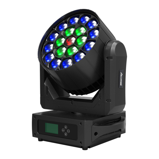
2. Technical Specifications Power Voltage: AC 100~240V, 50/60Hz Power Consumption: 680W Light Source: 19x40W RGBY LED Zoom Range: 5°~50° Movement: Pan: 540° Tilt: 220° Pan/Tilt Resolution: 16 bit Dimming/Strobe: Smooth dimming from 0~100%; outstanding strobe effect with variable speed Control: DMX channel: 15/27/17 channels Control Mode: DMX512, RDM Firmware Upgrade: Update via DMX link... -
Page 6: How To Set The Unit
3. How To Set The Unit 3.1 Control Panel 1. DISPLAY: To show the various menus and the selected functions 2. Button: MENU To enter into move backward or leave the menu DOWN To go forward in the selected functions To go backward in the selected functions ENTER To confirm the selected functions... -
Page 7: Main Function
3. DMX IN: DMX512 link, use 3/5-pin XLR cable to link the unit and the DMX controller 4. DMX OUT: DMX512 link, use 3/5-pin XLR cable to link the next unit and output DMX signal 5. POWER SWITCH: Turns on/off the power 6. - Page 9 DMX Settings Enter MENU mode, select DMX Settings, press the ENTER button to confirm, use the UP/DOWN button to select DMX Address, Channel Mode or View DMX Value. DMX Address To select DMX Address, press the ENTER button to confirm. Use the UP/DOWN button to adjust the address from 001 to 512, press the ENTER button to setup.
- Page 10 P/T Feedback To select P/T Feedback, press the ENTER button to confirm. Use the UP/DOWN button to select No (Pan or tilt’s position will not feedback while out of step) or Yes (Feedback while pan/tilt out of step), press the ENTER button to setup. Press the MENU button back to the last menu or let the unit idle one minute to exit menu mode.
- Page 11 Dimmer Speed To select Dimmer Speed, press the ENTER button to confirm. Use the UP/DOWN button to select Fast or Smooth. Once selected, press the ENTER button to setup. Press the MENU button back to the last menu or let the unit idle one minute to exit menu mode. Display Settings Enter MENU mode, select Display Settings, press the ENTER button to confirm, use the UP/DOWN button to select Display Invert, Backlight Intensity, Temperature Unit or Language.
- Page 12 Auto Test To select Auto Test, press the ENTER button to confirm, the unit will run built-in programs to automatically test pan, tilt, dimmer, shutter, spe.fun and etc. Press the MENU button back to the last menu or exit menu mode after auto test. Manual Test To select Manual Test, press the ENTER button to confirm.
- Page 13 Error Logs Select Error Logs, press the ENTER button to confirm. Use the UP/DOWN button to select Fixture Errors or Reset Error Log, press the ENTER button to store. Select Reset Error Log, press the ENTER button to confirm. Use the UP/DOWN button to select No or Yes, press the ENTER button to store. Select Yes, press the ENTER button to confirm.
-
Page 14: Home Position Adjustment
RDM FUNCTIONS Select the MANUFACTURER menu to display the manufacturer of the fixture. Select the SOFTWARE VERSION menu and the program version number of the fixture will be displayed. Select the DMX START ADDRESS menu to change the DMX 512 address (001-512). Select the DEVICE MODEL DESCRIPTION menu to display the model of the fixture. -
Page 15: Control By Universal Dmx Controller
4. Control By Universal DMX Controller 4.1 DMX512 Connection 1. At last unit, the DMX cable has to be terminated with a terminator. Solder a 120-ohm 1/4W resistor between pin 2(DMX-) and pin 3(DMX+) into a 3-pin XLR-plug and plug it in the DMX-output of the last unit. -
Page 16: Address Setting
4.2 Address Setting If you use a universal DMX controller to control the units, you have to set DMX address from 1 to 512 so that the units can receive DMX signal. Press the MENU button to enter menu mode, select DMX Settings, press the ENTER button to confirm, use the UP/DOWN button to select DMX Address, press the ENTER button to confirm, the present address will blinking the display, use the UP/DOWN button to adjust the address from 001 to 512, press the ENTER button to store. - Page 17 SPECIAL FUNCTIONS 000-126 No function 127-199 Focus compensate enable 200-209 Reset 210-255 No function DIMMER 000-255 0%100% 000-255 DIMMER FINE SHUTTER 000-019 Blackout 020-024 Open 025-064 Strobe 1: fastslow 065-069 Open 070-084 Strobe 2: opening pulse, fastslow 085-089 Open 090-104 Strobe 3: closing pulse, fastslow 105-109 Open...
- Page 18 045-049 Color8 050-054 Color9 055-059 Color10 060-064 Color11 065-069 Color12 070-074 Color13 075-079 Color14 080-084 Color15 085-089 Color16 090-094 Color17 095-099 Color18 100-104 Color19 105-109 Color20 110-114 Color21 115-119 Color22 120-124 Color23 125-129 Color24 130-134 Color25 135-139 Color26 140-144 Color27 145-149 Color28 150-154...
- Page 19 000-255 0°220° 000-255 TILT FINE PAN/TILT SPEED 000-255 fastslow ZOOM 000-255 60°10° SPECIAL FUNCTIONS 000-126 No function 127-199 Focus compensate enable 200-209 Reset 210-255 No function DIMMER 000-255 0%100% 000-255 DIMMER FINE SHUTTER 000-019 Blackout 020-024 Open 025-064 Strobe 1: fastslow 065-069 Open 070-084...
- Page 20 000-009 Open 010-017 Color1 018-024 Color2 025-032 Color3 033-039 Color4 040-047 Color5 048-054 Color6 055-061 Color7 062-069 Color8 070-076 Color9 077-084 Color10 085-091 Color11 092-099 Color12 100-106 Color13 107-113 Color14 114-121 Color15 122-128 Color16 129-136 Color17 137-143 Color18 144-151 Color19 152-158 Color20 159-165...
- Page 21 000-255 YELLOW 3 (0%100%) COLOR 3 000-255 (The same as CH15: COLOR 1) EFFECT 000-007 008-022 Effect1 023-037 Effect2 038-052 Effect3 053-067 Effect4 068-082 Effect5 083-097 Effect6 098-112 Effect7 113-127 Effect8 128-142 Effect9 143-157 Effect10 158-172 Effect11 173-187 Effect12 188-202 Effect13 203-217 Effect14...
- Page 22 000-255 DIMMER FINE SHUTTER 000-019 Blackout 020-024 Open 025-064 Strobe 1: fastslow 065-069 Open 070-084 Strobe 2: opening pulse, fastslow 085-089 Open 090-104 Strobe 3: closing pulse, fastslow 105-109 Open 110-124 Strobe 4: random strobe, fastslow 125-129 Open 130-144 Strobe 5: random opening pulse, fastslow 145-149 Open 150-164...
- Page 23 080-084 Color15 085-089 Color16 090-094 Color17 095-099 Color18 100-104 Color19 105-109 Color20 110-114 Color21 115-119 Color22 120-124 Color23 125-129 Color24 130-134 Color25 135-139 Color26 140-144 Color27 145-149 Color28 150-154 Color29 155-159 Color30 160-164 Color31 165-169 Color32 170-174 Color33 175-179 Open 180-201 Color33Color1 202-207...
-
Page 24: Troubleshooting
143-151 Effect16 152-160 Effect17 161-179 Effect18 170-178 Effect19 179-187 Effect20 188-196 Effect21 197-205 Effect22 206-214 Effect23 215-223 Effect24 224-232 Effect25 233-241 Effect26 242-250 Effect27 251-255 Effect28 EFFECT SPEED 000-127 SlowFast 128-255 Fade slowFade fast 5. Troubleshooting Following are a few common problems that may occur during operation. Here are some suggestions for easy troubleshooting: A. -
Page 25: Fixture Cleaning
6. Fixture Cleaning The cleaning of internal and external optical lenses and/or mirrors must be carried out periodically to optimize light output. Cleaning frequency depends on the environment in which the fixture operates: damp, smoky or particularly dirty surrounding can cause greater accumulation of dirt on the unit’s optics. - Page 28 Innovation, Quality, Performance...
Need help?
Do you have a question about the GLAMOUR 700Z RGBY and is the answer not in the manual?
Questions and answers