Table of Contents
Advertisement
Quick Links
Advertisement
Table of Contents

Related Manuals for Torque F9


Summary of Contents for Torque F9
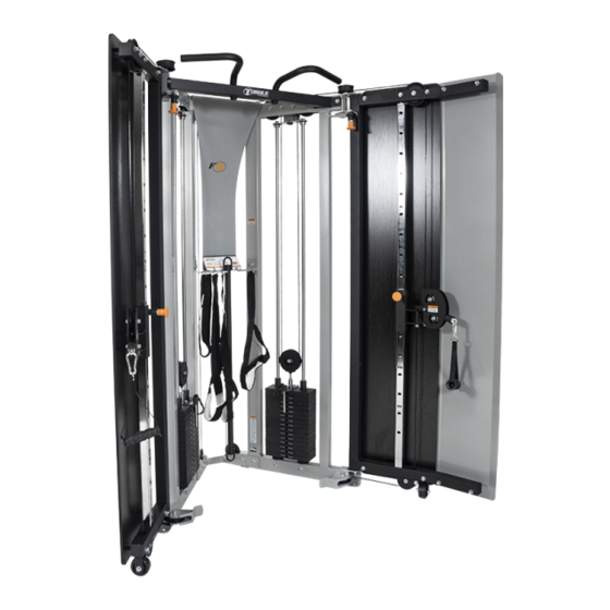
- Page 1 F9 ASSEMBLY GUIDE VERSION: F9-003-150LB/200LB PART #: 5726401-B...
-
Page 2: Table Of Contents
TABLE OF CONTENTS Important safety instructions: • Important safety instructions for using equipment: Page 3 • Important safety instructions for assembling equipment: Page 3 • Obtaining service: Page 3 General Notes: • Unpacking equipment: Page 4 • Tools Required: Page 4 •... -
Page 3: Important Safety Instructions For Using Equipment
Do not disassemble, remove any parts or components or otherwise attempt to repair this product. DO NOT use product if product appears damaged. DO NOT attempt to fix a broken or jammed machine, obtain assistance from your authorized Torque Fitness Dealer. Failure to comply with these instructions will void any and all product warranties. -
Page 4: General Notes
If any items are missing, contact Torque Fitness Customer service at: 763-754-7533 (8:30 am - 5:00 pm • A 6" scale is provided at the bottom of •... -
Page 5: Parts List
WORKOUT BOOK, F9-101 NOTE: The F9 has two weight stack options. 150 LBS. and 200 LBS. * The 150 LB. stack has fourteen 10 LB. plates and a head plate. ** The 200 LB. stack has ten 15 LB. plates, 4 ten LB. plates and a... -
Page 6: Assembly Instructions: Pages
STEP 1 6 3/8 X 3" (76mm) LOOSELY assemble bolt connections in this step. - Page 7 STEP 2 6 3/8 X 3" (76mm) LOOSELY assemble bolt connections in this step.
- Page 8 STEP 3 3/8 X 3" (76mm) LOOSELY assemble bolt connections in this step.
- Page 9 STEP 4 11 3/8 X 2-3/4" (70mm) LOOSELY assemble bolt connections in this step.
- Page 10 STEP 5 13 3/8 X 3-3/4" (95mm) 11 3/8 X 2-3/4" (70mm) LOOSELY assemble bolt connections in this step.
- Page 11 STEP 6 (2X) 11 3/8 X 2-3/4" (70mm) After this step has been assembled, SECURELY tighten all bolt connections from this step and previous steps.
- Page 12 STEP 7 150 LB OPTION 200 LB OPTION...
- Page 13 STEP 8 11 3/8 X 2-3/4" (70mm) Tighten set screws 3/8 X 2-1/2" (64mm) NOTE: Lift up on guide rod and insert bolt underneath SECURELY tighten all bolt connections in this step.
- Page 14 STEP 9 150 LB OPTION 200 LB OPTION...
- Page 15 STEP 10 3/8 X 2-3/4" (70mm) Tighten set screws 22 3/8 X 2-1/2" (64mm) NOTE: Lift up on guide rod and insert bolt underneath SECURELY tighten all bolt connections in this step.
- Page 16 STEP 11...
- Page 17 STEP 12 3/8 X 2-3/4" (70mm) 3/8 X 1" (25mm) W/NP SECURELY tighten all bolt connections in this step.
- Page 18 STEP 13 SECURELY tighten all bolt connections in this step.
- Page 19 STEP 14...
- Page 20 STEP 15 11 3/8 X 2-3/4" (70mm) 26 3/8 X 1" (25mm) W/NP SECURELY tighten all bolt connections made in this step.
- Page 21 STEP 16 SECURELY tighten all bolt connections in this step.
- Page 22 STEP 17 22 3/8 X 2-1/2" (64mm) NOTE: Before tightening, make sure wheel contacts floor. Wheel may have to be re-adjusted if door is difficult to open and close. SECURELY tighten all bolt connections in this step.
- Page 23 STEP 18 3/8 X 2-1/2" (64mm) NOTE: Before tightening, make sure wheel contacts floor. Wheel may need to be re-adjusted if door is difficult to open and close. SECURELY tighten all bolt connections in this step.
- Page 24 STEP 19 3/8 X 1-3/4" (45mm) W/NP 32 3/8 X 1-3/4" (45mm) SECURELY tighten all bolt connections in this step.
- Page 25 STEP 20 34 3/8 X 1-3/4" (45mm) W/NP 3/8 X 1-3/4" (45mm) SECURELY tighten all bolt connections in this step.
- Page 26 STEP 21 NOTE: Discard labels 16-20 1/2" NOTE: Apply the weight stack labels to the RIGHT SIDE VIEW left of the holes on weight plates by following the installation instructions printed on the label. NOTE: After weight stack labels have been applied, use a rubber mallet to carefully install insert plug of the weight stack pin into the center hole of the head plate.
- Page 27 STEP 22 1-1/4" ASSEMBLED VIEW 3/8 X 3/4" (19mm) W/NP SECURELY tighten all bolt connections in this step.
- Page 28 STEP 23 NOTE: Discard labels 16-20 1/2" LEFT SIDE VIEW NOTE: Apply the weight stack labels to the left of the holes on weight plates by following the installation instructions printed on the label. NOTE: After weight stack labels have been applied, use a rubber mallet to carefully install insert plug of the weight stack pin into the center hole of the head plate.
- Page 29 STEP 24 1-1/4" ASSEMBLED VIEW 3/8 X 3/4" (19MM) W/NP SECURELY tighten all bolt connections in this step.
- Page 30 STEP 25 CABLE ROUTING TO START: THREAD JAM NUT ON TO CABLE END. THREAD CABLE END INTO CARRIAGE AS SHOWN IN INSET VIEW. ROUTE CABLE IN DIRECTION OF ARROWS. SEE CAUTIONS BELOW. CAUTION: MAKE SURE CABLE IS ROUTED UNDER FRAME BOLTS RIGHT SIDE CAUTION: When routing cables, make sure that the cables are seated in the groove of the pulleys and underneath all retaining bolts, pins or...
- Page 31 STEP 26a 4) ASSEMBLE 45 TO 44 1) SLIDE OVER CABLE END 2) SLIDE OVER CABLE END 3) SLIDE OVER CABLE END NOTE: Before begining this step, lift the head plate up and insert the weight stack pin into the 5th hole of the stem and set it back down on top of the first weight plate SECURELY tighten all bolt connections in this step.
-
Page 32: Cable Adjustments: Pages 32
STEP 26b CABLE ADJUSTMENT NOTE 2: If there is a gap between the head plate and first plate, loosen jam nut and turn threaded end clockwise until the head plate touches the first plate. SECURELY tighten jam nut To add tension to the cable, turn NOTE 1: the threaded end counter clockwise. - Page 33 STEP 27 CABLE ROUTING TO START: THREAD JAM NUT ON TO CABLE END. THREAD CABLE END INTO CARRIAGE AS SHOWN IN INSET VIEW. ROUTE CABLE IN DIRECTION OF ARROWS. SEE CAUTIONS BELOW. CAUTION: MAKE SURE CABLE IS ROUTED UNDER FRAME BOLTS. LEFT SIDE CAUTION: When routing cables, make sure that the cables are seated in the groove of the pulleys and underneath all retaining bolts, pins or...
- Page 34 STEP 28a 1) SLIDE OVER CABLE END 4) ASSEMBLE (45) TO (44) 2) SLIDE OVER CABLE END 3) SLIDE OVER CABLE END NOTE: Before begining this step, lift the head plate up and insert the weight stack pin into the 5th hole of the stem and set it back down on top of the first weight plate SECURELY tighten all bolt connections in this step.
- Page 35 STEP 28b CABLE ADJUSTMENT NOTE 2: If there is a gap between the head plate and first plate, loosen jam nut and turn threaded end clockwise until the head plate touches the first plate. SECURELY tighten jam nut. To add tension to the cable, turn the threaded end counter clockwise.
- Page 36 STEP 29 3/8 X 4" (102mm) SECURELY tighten all bolt connections in this step.
- Page 37 STEP 30 48 3/8 X 4" (102mm) SECURELY tighten all bolt connections in this step.
- Page 38 STEP 31 3/8 X 4-1/2" (114mm) SECURELY tighten all bolt connections in this step.
-
Page 39: Attachment And Adjustment Instructions
STEP 32... -
Page 40: Maintenance
Tighten spring pin nuts as needed. FRAME: Wipe down and damp cloth. GRIPS: Inspect and replace if they appear worn or damaged. For customer service contact Torque Fitness Customer service at: 763-754- 7533 (8:30 am - 5:00 pm CST). or 1-877-TORQUE5 (1-866-664-9894). -
Page 41: Resistance Ratio Chart
ONE HEAD PLATE FOURTEEN 10 LB PLATES 150 LB STACK ONE HEAD PLATE FOUR 10 LB PLATES 15 LB PLATES 200 LB STACK...
Need help?
Do you have a question about the F9 and is the answer not in the manual?
Questions and answers