Torque TANK M1 Assembly Manual
Hide thumbs
Also See for TANK M1:
- Assembly manual (11 pages) ,
- Assembly manual (17 pages) ,
- Assembly manual (25 pages)
Table of Contents
Advertisement
Quick Links
Advertisement
Table of Contents

Related Manuals for Torque TANK M1


Summary of Contents for Torque TANK M1
-
Page 1: 58027Pa Ptd Assy, Lower Mount (Optional)
TANK M1 ASSEMBLY GUIDE VERSION: XTTM1-RPH-101 PART #: 5706201-D... -
Page 2: Table Of Contents
SCREW, M8-1.25 X 20L SOC HD GR 12.9 TABLE OF CONTENTS: 2010801 WASHER, STEEL 12.7 ID-25 OD-2 THK CLEAR ZINC • TANK M1 ASSEMBLY: PAGES 3 - 5 5654501 ASSY, REAR WHEEL 10" DIA X 3" WIDE • TANK M1 ADJUSTMENTS: PAGES 6 - 7 •... -
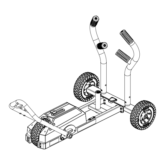
Page 3: Tank M1 Assembly: Pages
STEP 1 NOTE: LOOSELY tighten bolt connections in this step... - Page 4 STEP 2 NOTE: Before assembling tires, check tire pressure. Make sure tires are inflated to 30 PSI NOTE: After tires have been securely assembled, SECURELY tighten these bolts NOTE: SECURELY tighten all bolt connections in this step and previous step...
- Page 5 STEP 3 NOTE Match "R" LABEL on RIGHT PUSH HANDLE with "R" LABEL on REAR FRAME NOTE: Align pin in PUSH HANDLES with slot in RECEIVER TUBE NOTE Match "L" LABEL on LEFT PUSH HANDLE with "L" LABEL on REAR FRAME...
-
Page 6: Tank M1 Adjustments: Pages
TANK M1 RESISTANCE ADJUSTMENT PULL BACK ADJUSTER TO INCREASE RESISTANCE POSITION N: NEUTRAL POSITION 1: LOW RESISTANCE POSITION 2: MEDIUM RESISTANCE POSITION 3: HARD RESISTANCE... - Page 7 TANK M1 PUSH/PULL BAR ADJUSTMENT PUSH/PULL BAR PULL SPRING PIN AND ROTATE PUSH/PULL BAR FORWARD...
-
Page 8: 2001101 Washer, Flat 3/8 Sae St Zn
TANK OPERATION PUSH PUSH PULL See following pages for optional accessories PUSH MAX WEIGHT PLATES: 2 - 45 LB BUMPER PLATES 3 - 45 LB GRIP PLATES NOTE: Weight plates are not included. Weight plates are only needed to prevent skidding and lifting of the back wheels. Adding weight does not affect the resistance... -
Page 9: Optional Attachments
Weight plates are not included. Weight plates are only needed to prevent skidding and lifting of the back wheels. Adding weight does not affect the resistance To discover what accessories pair well with the TANK M1, visit our web site at: www.torquefitness.com/collections/tank-accessories. or by phone at 877-767-7835... - Page 10 Weight plates are not included. Weight plates are only needed to prevent skidding and lifting of the back wheels. Adding weight does not affect the resistance To discover what accessories pair well with the TANK M1, visit our web site at: www.torquefitness.com/collections/tank-accessories. or by phone at 877-767-7835...
- Page 11 WHEELBARROW HANDLE ATTACHMENT (OPTIONAL) NOTE NOTE: Match "R" LABEL on RIGHT Align pin in WHEEL- WHEELBARROW HANDLE BARROW HANDLE with "R" LABEL on REAR FRAME with SLOT in RECEIVER TUBE NOTE Match "L" LABEL on LEFT WHEELBARROW HANDLE with "L" LABEL on REAR FRAME...
-
Page 12: Tank M1 Storage (Optional)
XTM1-WMSS WALL MOUNT STORAGE SYSTEM (OPTIONAL) WARNING: The UPPER MOUNT MUST be anchored to the wall using four WALL ANCHORS suitable for that particular wall construction 1-3/4" 36" 1-3/4" 6" (MIN) NOTES: FLOOR The images above show the anchoring hardware used for attaching to WARNING: typical walls with wood studs spaced 16"... - Page 13 XTM1-WMSS WALL MOUNT STORAGE SYSTEM (OPTIONAL) M1 STORAGE NOTE: These LOOPS are for attaching RESISTANCE BANDS and INERTIA WAVE MAX BAND RESISTANCE = 50 LBS. NOTE: These areas are for ATTACHING BATTLE ROPES, RESISTANCE BANDS and INERTIA WAVE MAX BAND RESISTANCE = 50 LBS...
- Page 14 XTM1-WMSS WALL MOUNT STORAGE SYSTEM (OPTIONAL) PUSH HANDLE STORAGE...
- Page 15 XTM1-WMSS WALL MOUNT STORAGE SYSTEM (OPTIONAL) WHEELBARROW HANDLE STORAGE...
-
Page 16: Inspection & Lubrication
INSPECTION & LUBRICATION INSPECTION: ATTENTION: PLEASE ENSURE THAT ALL TIRES ARE INFLATED TO 30 PSI. FAILURE TO DO SO MAY RESULT IN TANK VEERING DURING USE. Once a month, check for loose bolts on frame and wheels. Tighten if necessary. Once a month, remove shroud as shown on PAGE 16 and check that the chain and sprockets are clean, free of rust, dust and grime. -
Page 17: Shroud Removal
SHROUD REMOVAL - STEP 1 SHROUD REMOVAL - STEP 2 USE A PHILLIPS SCREW DRIVER TO LOOSEN AND REMOVE 6 SCREWS AS SHOWN. CAREFULLY LIFT SHROUD OFF M1. BOTTOM VIEW USE A PHILLIPS SCREW DRIVER TO LOOSEN AND REMOVE 2 SCREWS AND CAREFULLY REMOVE HANDLE. -
Page 18: Chain Adjustment
CHAIN ADJUSTMENT TO SET THE CORRECT CHAIN TENSION FOLLOW THESE STEPS: 1) TIP M1 BACK SO THAT IT RESTS ON THE REAR WHEELS AND PUSH HANDLES. AS SHOWN. 2) LOOSEN ALL FOUR BOLTS ONE FULL TURN EACH. (BOLT SHOULD BE LOOSE ENOUGH TO ALLOW THE BRAKE MODULE TO MOVE). -
Page 19: Safety And Warning Notices
DO NOT place more than 135 LBS. on the weight horn of the TANK M1. • DO NOT drop the weight plates onto the TANK M1. Doing so, may result in damage to the TANK M1. DO NOT use the TANK M1 in wet or slippery conditions.
Need help?
Do you have a question about the TANK M1 and is the answer not in the manual?
Questions and answers