Advertisement
Quick Links
Advertisement

Subscribe to Our Youtube Channel
Related Manuals for Torque F9W


Summary of Contents for Torque F9W
- Page 1 F9W ASSEMBLY GUIDE VERSION: F9W-001-150LB/200LB/225LB PART #: 5775001-C...
- Page 2 TABLE OF CONTENTS Important safety instructions: • Important safety instructions for using equipment: Page 3 • Important safety instructions for assembling equipment: Page 3 • Obtaining service: Page 3 General Notes: • Unpacking equipment: Page 4 • Tools Required: Page 4 •...
- Page 3 Do not disassemble, remove any parts or components or otherwise attempt to repair this product. DO NOT use product if product appears damaged. DO NOT attempt to fix a broken or jammed machine, obtain assistance from your authorized Torque Fitness Dealer. Failure to comply with these instructions will void any and all product warranties.
-
Page 4: General Notes
If any items are missing, contact Torque Fitness Customer service at: 763-754-7533 (8:30 am - 5:00 pm • A 6" scale is provided at the bottom of •... - Page 5 ITEM PART NUMBER DESCRIPTION ITEM PART NUMBER DESCRIPTION 55181PA PTD ASSY, WEIGHT SELECTOR STORAGE PLATE 57514PA PTD ASSY, BASE 57525PA PTD ASSY, CORNER UPRIGHT TUBE 54970PA PTD ASSY, HEAD PLATE PULLEY 2009402 BOLT, 3/8-16 X 3/4" (19mm) ST HT SOCKET HEAD W/NP 5752501 TUBE, CORNER UPRIGHT 2001101...
- Page 6 STEP 1 NOTE: CORNER UPRIGHT TUBES are shown in assembled position. NOTE: LOOSELY assemble bolt connections in this step.
- Page 7 STEP 2 NOTE: LOOSELY assemble bolt connections in this step.
- Page 8 STEP 3 NOTE: TOP BOOM is shown in assembled position NOTE: LOOSELY assemble bolt connections in this step.
-
Page 9: Wall Mount Brackets
STEP 4 NOTE: WALL MOUNT BRACKETS are shown in assembled position NOTE: Once this step has been completed, SECURELY tighten all bolt connections in this step and previous steps. - Page 10 STEP 5 WARNING: The UPPER and LOWER WALL MOUNT BRACKETS MUST be anchored to the wall using 12 wall anchors suitable for that particular wall construction. 16" 16" 2" 69-3/8" 2" NOTES: 9" The images above show anchoring hardware used for attaching the WALL MOUNT BRACKETS to a typical wall with wood studs spaced 16"...
- Page 11 STEP 6 (150 LB OPTION) STEP 6 (200 LB OPTION) STEP 6 (225 LB OPTION)
- Page 12 STEP 7 NOTE 2: After everything has been assembled, slide SHAFT COLLARS up to GUIDE ROD SUPPORT and tighten set screws. NOTE 1: Lift up on GUIDE RODS and insert bolts underneath NOTE: SECURELY tighten bolt connections in this step.
- Page 13 STEP 8 (150 LB OPTION) STEP 8 (200 LB OPTION) STEP 8 (225 LB OPTION)
- Page 14 STEP 9 NOTE 2: After everything has been assembled, slide SHAFT COLLARS up to GUIDE ROD SUPPORT and tighten set screws. NOTE 1: Lift up on GUIDE RODS and insert bolts underneath NOTE: SECURELY tighten bolt connections in this step.
- Page 15 STEP 10...
- Page 16 STEP 11 NOTE: SECURELY tighten bolt connections in this step.
- Page 17 STEP 12 NOTE: SECURELY tighten bolt connections in this step.
- Page 18 STEP 13...
- Page 19 STEP 14 NOTE: SECURELY tighten bolt connections in this step.
- Page 20 STEP 15 NOTE: SECURELY tighten bolt connections in this step.
- Page 21 STEP 16 NOTE: Before tightening, make sure WHEEL contacts floor. WHEEL may have to be re-adjusted if floor is not level or if door is difficult to open or close NOTE: SECURELY tighten bolt connections in this step.
- Page 22 STEP 17 NOTE: Before tightening, make sure WHEEL contacts floor. WHEEL may have to be re-adjusted if floor is not level or if door is difficult to open or close NOTE: SECURELY tighten bolt connections in this step.
- Page 23 STEP 18 NOTE: SECURELY tighten bolt connections in this step.
- Page 24 STEP 19 NOTE: SECURELY tighten bolt connections in this step.
- Page 25 STEP 20 NOTE: NOTE: After WEIGHT STACK LABELS have been Apply the WEIGHT STACK LABELS to applied, use a rubber mallet to carefully the left of the holes on WEIGHT PLATES install INSERT PLUG of the WEIGHT STACK by following the installation instructions PIN into the center hole of the HEAD PLATE printed on the LABEL...
-
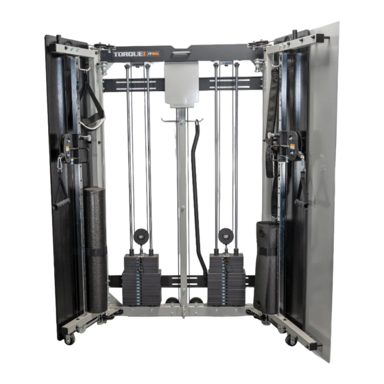
Page 26: Assembled View
STEP 21 1-1/2" ASSEMBLED VIEW NOTE: SECURELY tighten bolt connections in this step. - Page 27 STEP 22 (RIGHT CABLE ASSEMBLY) 1" (25mm) STEP 22a: Thread a JAM NUT on bolt end of CABLE. Thread bolt end of Ball end of CABLE CABLE into CARRIAGE as shown in inset above. Route CABLE in direction of arrows. See CAUTIONS below. STEP 22b: Route ball end of CABLE through DOOR and around PULLEYS.
- Page 28 STEP 23 (RIGHT CABLE ASSEMBLY) STEP 23c Route CABLE around these four PULLEYS STEP 23a Route CABLE around these two PULLEYS STEP 23d Route CABLE around pulley Ball end of CABLE STEP 23b Route CABLE around PULLEY NOTE: Make sure CABLE is in groove of PULLEY NOTE: Make sure CABLE...
- Page 29 STEP 24A (RIGHT CABLE ASSEMBLY) 4) Slide 40 over 41 & 42 then assemble 43 to 42 1) Slide 40 over CABLE end 2) Slide 41 over CABLE end 3) Slide 42 on to CABLE end NOTE: Before begining this step, lift HEAD PLATE up and insert WEIGHT STACK PIN into bottom hole of stem and set back down on top of first WEIGHT PLATE...
- Page 30 STEP 24B (RIGHT CABLE ADJUSTMENT) NOTE 2: If there is a gap between HEAD PLATE and first WEIGHT PLATE, loosen JAM NUT and turn bolt end clockwise until HEAD PLATE touches first WEIGHT PLATE. SECURELY tighten JAM NUT. If CABLE has to much slack, loosen JAM NUT and turn bolt end counter NOTE 1: Lift HEAD PLATE up and remove...
- Page 31 STEP 25 (LEFT CABLE ASSEMBLY) STEP 25a: Thread a JAM NUT on bolt end of CABLE. Thread bolt end of Ball end of CABLE CABLE into CARRIAGE as shown in inset above. Route CABLE in direction of arrows. See CAUTIONS below STEP 25b: Route ball end of CABLE through DOOR and around PULLEY.
- Page 32 STEP 26 (LEFT CABLE ASSEMBLY) STEP 26c STEP 26a Route CABLE around Route CABLE over these four PULLEYS these two PULLEYS STEP 26d Route CABLE around PULLEY Ball end of CABLE STEP 26b Route CABLE around PULLEY NOTE: Make sure CABLE is in groove of PULLEYS CAUTION: When routing CABLE, make sure CABLE is seated in groove of...
- Page 33 STEP 27A (LEFT CABLE ASSEMBLY) 1) Slide 40 over CABLE end 4) Slide 40 over 41 & 42 then assemble 43 to 42 2) Slide 41 over CABLE end NOTE: 3) Slide 42 on to Before begining this step, lift HEAD CABLE end PLATE up and insert WEIGHT STACK PIN into bottom hole of stem and set back...
- Page 34 STEP 27B (LEFT CABLE ADJUSTMENT) NOTE 2: If there is a gap between HEAD PLATE and first WEIGHT PLATE, loosen JAM NUT and turn bolt end clockwise until HEAD PLATE touches first WEIGHT PLATE. SECURELY tighten JAM NUT. NOTE 1: Lift HEAD PLATE up and remove WEIGHT STACK PIN.
- Page 35 STEP 28 NOTE: SECURELY tighten bolt connections in this step.
- Page 36 STEP 29 NOTE: LOOSELY tighten bolt connections in this step.
- Page 37 STEP 30 NOTE: Assemble TOB BOOM SHROUD to bottom of pulley shaft (2 places). NOTE: TOP BOOM SHROUD has been hidden for assembly clarity NOTE: Once this step has been completed, SECURELY tighten all bolt connections in this step and previous step.
- Page 38 STEP 31 NOTE: ROLLER/MAT HOLDER is shown in assembled position NOTE: SECURELY tighten bolt connections in this step.
- Page 39 STEP 32 NOTE: SECURELY tighten bolt connections in this step.
- Page 40 STEP 33 NOTE: ROLLER/MAT HOLDER is shown in assembled position NOTE: SECURELY tighten bolt connections in this step.
- Page 41 STEP 34 NOTE: SECURELY tighten bolt connections in this step.
- Page 42 STEP 35 NOTE: NOTE: Peel backing from BUMPERS Clean six areas with 1-1/4" 1-1/4" and stick BUMPER to the inside rubbing alcohol surface of FRONT DOOR SHROUD as shown in INSIDE VIEW 3" 40-1/4" 3" SHROUD INSIDE VIEW...
- Page 43 STEP 36 NOTE: SECURELY tighten bolt connections in this step.
- Page 44 STEP 37 NOTE: Attach RESISTANCE BANDS here NOTE: Insert FOAM ROLLER or rolled up MAT here...
- Page 45 STEP 38 NOTE: Narrow position NOTE: To use the PULL-UP/PRESS BAR, adjust LEFT and RIGHT DOORS to the narrow position...
- Page 46 OPTIONAL KETTLBELL/DUMBBELL STORAGE: STEP 1 Loosen and remove the three bolts and washers from Center Upright...
- Page 47 OPTIONAL KETTLBELL/DUMBBELL STORAGE: STEP 2 XCREATE-VDS5 XCREATE-VDS4 VKBS4 VERTICAL DUMBBELL VERTICAL DUMBBELL VERTICAL KETTLEBELL STORAGE 5 PAIR STORAGE 4 PAIR STORAGE 4 TRAYS SECURELY assemble KETTLEBELL STORAGE SECURELY assemble SECURELY assemble to CENTER UPRIGHT DUMBBELL STORAGE DUMBBELL STORAGE using three bolts and to CENTER UPRIGHT to CENTER UPRIGHT washers from previous step...
-
Page 48: Maintenance
Tighten spring pin nuts as needed. FRAME: Wipe down and damp cloth. GRIPS: Inspect and replace if they appear worn or damaged. For customer service contact Torque Fitness Customer service at: 763-754- 7533 (8:30 am - 5:00 pm CST). or NOTE: 1-877-TORQUE5 (1-866-664-9894).
Need help?
Do you have a question about the F9W and is the answer not in the manual?
Questions and answers