Agora Models SHELBY COBRA 427 SEMI-COMPETITION 1965 Build Instructions
1:8 scale
Hide thumbs
Also See for SHELBY COBRA 427 SEMI-COMPETITION 1965:
- Build instructions (36 pages) ,
- Build instructions (31 pages)
Advertisement
Quick Links
In the 1960s, Carroll Shelby's Cobras dominated racetracks worldwide, first winning races coast to coast
across North America, then in 1965, winning the World Manufacturer's GT Championship, achieving the
ultimate goal of defeating Ferrari. The Semi-Competitions were modified from full competition models
just enough to make them street legal. Only 29 models were produced, making them one of the most
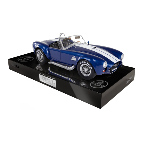
Your 1:8 model replicates the original 1965 Semi-Competition Cobra in intricate detail. From the detail on
the dashboard dials to the writing on the wheels, every piece is precisely reproduced.
In your second model pack, you will continue to build the Cobra 427 engine:
STAGE 07: ASSEMBLING THE ALTERNATOR
STAGE 08: WATER PUMP PULLEY, CRANK
SHAFT PULLEY AND TIMING BELT COVER
STAGE 09: LEFT CYLINDER HEAD COVER AND
EXHAUST MANIFOLD PIPES
STAGE 10: RIGHT CYLINDER HEAD COVER AND
EXHAUST MANIFOLD PIPES
STAGE 11: ROCKER COVERS , CAPS AND SPARK
WIRE HOLDERS
AGORAMODELS
Pack 02 | Build Instructions
sought-after American sports cars by collectors.
STAGE 12: DISTRIBUTOR, FUEL FILTER,
IGNITION COIL AND CYLINDER HEAD CAP
STAGE 13: ENGINE BLOCKS AND COOLING
FLUID TANK BRACKET
STAGE 14: FLYWHEEL COVER, GEARBOX,
INSPECTION COVER, GEARBOX RODS
STAGE 15: OIL PAN, PROTECTIVE PLATE ,
SPARK PLUGS , SPARK PLUG WIRE AND WIRE
CONNECTORS
1
SHELBY COBRA 427 S/C
Advertisement

Related Manuals for Agora Models SHELBY COBRA 427 SEMI-COMPETITION 1965


Summary of Contents for Agora Models SHELBY COBRA 427 SEMI-COMPETITION 1965
- Page 1 Pack 02 | Build Instructions In the 1960s, Carroll Shelby’s Cobras dominated racetracks worldwide, first winning races coast to coast across North America, then in 1965, winning the World Manufacturer’s GT Championship, achieving the ultimate goal of defeating Ferrari. The Semi-Competitions were modified from full competition models just enough to make them street legal.
- Page 2 Stage 07: Assembling the Alternator In stage 07, you will add the alternator to the oil filter assembly from stage 05. S T A G E 0 7 P A R T S L I S T Name Quantity Alternator housing Alternator bottom Pulley Mounting plate...
- Page 3 Stage 07: Assembling the Alternator S T E P 1 A S S E M B L E T H E A LT E R N A T O R A N D A T T A C H I T T O T H E O I L F I LT E R A S S E M B LY Align the two lugs on the alternator housing with the tiny holes on the alternator bottom.
- Page 4 Stage 07: Assembling the Alternator S T E P 2 Align the tiny holes on the mounting arm and the alternator as shown (study the photo carefully to check you have the parts the correct way up). Fix together using a TYPE OP06 screw. Align the holes on the mounting plate and the alternator in a similar way, and fix using another TYPE OP06 screw, taking care not to overtighten.
- Page 5 Stage 07: Assembling the Alternator Stage 07 complete! AGORAMODELS SHELBY COBRA 427 S/C...
- Page 6 Stage 08: Water Pump Pulley, Crank Shaft Pulley and Timing Belt Cover In stage 08, you will continue to build the engine S T A G E 0 8 P A R T S L I S T Name Quantity Timing Belt Cover Timing Belt Water Pump Pulley Part 1...
- Page 7 Stage 08: Water Pump Pulley, Crank Shaft Pulley and Timing Belt Cover S T E P 1 A S S E M B L E T H E W A T E R P U M P A N D C R A N K S H A F T P U L L E Y S Hold the water pump pulley part 1 so that the two lugs are facing up.
- Page 8 Stage 08: Water Pump Pulley, Crank Shaft Pulley Stage 08: Water Pump Pulley, Crank Shaft Pulley and Timing Belt Cover and Timing Belt Cover S T E P 2 A T T A C H T H E P U L L E Y S A N D T I M I N G B E LT C O V E R Align the lug on the water pump pulley with the hole on the assembly from stage 07.
- Page 9 Stage 08: Water Pump Pulley, Crank Shaft Pulley and Timing Belt Cover Stage 08 complete! AGORAMODELS SHELBY COBRA 427 S/C...
- Page 10 Stage 09: Left Cylinder Head Cover and Exhaust Manifold Pipes In stage 09 you will continue to build the engine. S T A G E 0 9 P A R T S L I S T Name Quantity Left Cylinder Head Cover Exhaust Manifold Pipe 1 Exhaust Manifold Pipe 2 Exhaust Manifold Pipe 3...
- Page 11 Stage 09: Left Cylinder Head Cover and Exhaust Manifold Pipes S T E P 1 A S S E M B L E T H E L E F T C Y L I N D E R H E A D Note that the left cylinder head has numbered holes along its length: 1, 4, 3, 2.
- Page 12 Stage 10: Right Cylinder Head Cover and Exhaust Manifold Pipes In stage 10 you will continue to build the engine. S T A G E 1 0 P A R T S L I S T Name Quantity Right Cylinder Head Cover Exhaust Manifold Pipe 5 Exhaust Manifold Pipe 6 Exhaust Manifold Pipe 7...
- Page 13 Stage 10: Right Cylinder Head Cover and Exhaust Manifold Pipes S T E P 1 A S S E M B L E T H E R I G H T C Y L I N D E R H E A D Note that the right cylinder head has numbered holes along its length: 6, 7, 8, 5.
- Page 14 Stage 11: Rocker Covers, Caps and Spark Wire Holders In stage 11, the engine will continue to take shape. S T A G E 1 1 P A R T S L I S T Name Quantity Left Rocker Cover Left Rocker Cover Cap Left Spark Wire Holder Right Rocker Cover...
- Page 15 Stage 11: Rocker Covers, Caps and Spark Wire Holders S T E P 1 A T T A C H T H E R O C K E R C O V E R C A P S Take the right rocker cover cap and align it with the hole on the right rocker cover.
- Page 16 Stage 11: Rocker Covers, Caps and Spark Wire Holders S T E P 2 A T T A C H T H E R O C K E R C O V E R S T O T H E E X H A U S T M A N I F O L D S Align the left cylinder head cover from stage 10 with the left rocker cover.
- Page 17 Stage 11: Rocker Covers, Caps and Spark Wire Holders S T E P 3 A T T A C H T H E S P A R K W I R E H O L D E R S Push the spark wire holders into position on the left and right rocker covers as shown.
- Page 18 Stage 11: Rocker Covers, Caps and Spark Wire Holders Stage 11 complete! AGORAMODELS SHELBY COBRA 427 S/C...
- Page 19 Stage 12: Distributor, Fuel Filter, Ignition Coil and Cylinder Head Cap In stage 12 the engine will continue to take shape. S T A G E 1 2 P A R T S L I S T Name Quantity Ignition Distributor Ignition Coil Cylinder Head Central Cover cap Fuel Filter...
- Page 20 Stage 12: Distributor, Fuel Filter, Ignition Coil and Cylinder Head Cap S T E P 1 A D D C O M P O N E N T S T O T H E E N G I N E B L O C K A S S E M B LY Take the engine block assembly from Stage 04 and position the distributor in one corner as shown.
- Page 21 Stage 12: Distributor, Fuel Filter, Ignition Coil and Cylinder Head Cap S T E P 2 A D D C O M P O N E N T S T O T H E L E F T C Y L I N D E R H E A D A S S E M B LY Take the left cylinder head assembly from stage 09.
- Page 22 Stage 12: Distributor, Fuel Filter, Ignition Coil and Cylinder Head Cap Stage 12 complete! AGORAMODELS SHELBY COBRA 427 S/C...
- Page 23 Stage 13: Engine Blocks and Cooling Fluid Tank Bracket In stage 13 the engine will continue to take shape. S T A G E 1 3 P A R T S L I S T Name Quantity Left Engine Block Right Engine Block Cooling Fluid Tank Bracket Screws TYPE OD03...
- Page 24 Stage 13: Engine Blocks and Cooling Fluid Tank Bracket S T E P 1 A T T A C H T H E C Y L I N D E R H E A D S T O T H E E N G I N E B L O C K S Identify the left and right engine blocks by the letters ‘L’...
- Page 25 Stage 13: Engine Blocks and Cooling Fluid Tank Bracket Stage 13 complete! AGORAMODELS SHELBY COBRA 427 S/C...
- Page 26 Stage 14: Flywheel Cover, Gearbox, Inspection Cover, Gearbox Rods In stage 14 you will add gearbox components to the engine. S T A G E 1 4 P A R T S L I S T Name Quantity Left Flywheel Cover Left Right Flywheel Cover Right Left Gear Box Right Gear Box...
- Page 27 Stage 14: Flywheel Cover, Gearbox, Inspection Cover, Gearbox Rods S T E P 1 A S S E M B L E T H E G E A R B O X I N S P E C T I O N C O V E R A N D F LY W H E E L C O V E R S Take the inspection plate and fix 2 x TYPE OP07 screws into the two screw holes.
- Page 28 Stage 14: Flywheel Cover, Gearbox, Inspection Cover, Gearbox Rods S T E P 2 A T T A C H T H E G E A R B O X Mount the right gearbox (indicated by an ‘R’) and sit it on top of the flywheel parts. Fix in place with a TYPE OD03 screw.
- Page 29 Stage 14: Flywheel Cover, Gearbox, Inspection Stage 14: Flywheel Cover, Gearbox, Inspection Cover, Gearbox Rods Cover, Gearbox Rods S T E P 4 A T T A C H T H E G E A R B O X R O D S Identify the gearbox rods 1, 2 and 3.
- Page 30 Stage 14: Flywheel Cover, Gearbox, Inspection Cover, Gearbox Rods Stage 14 complete! AGORAMODELS SHELBY COBRA 427 S/C...
- Page 31 Stage 15: Oil Pan, Protective Plate, Spark Plugs, Spark Plug Wire and Wire Connectors In stage 15 you will assemble the engine components together and install the spark wires in the correct firing sequence! S T A G E 1 5 P A R T S L I S T Name Quantity Oil Pan...
- Page 32 Stage 15: Oil Pan, Protective Plate, Spark Plugs, Spark Plug Wire and Wire Connectors S T E P 1 A T T A C H T H E P R O T E C T I V E P L A T E T O T H E O I L P A N Take the oil pan and the protective plate, aligning the lug and holes as shown.
- Page 33 Stage 15: Oil Pan, Protective Plate, Spark Plugs, Spark Plug Wire and Wire Connectors S T E P 2 F I T T W O O D 0 4 S C R E W S T O T H E E N G I N E B L O C K Take the engine block assembly from stage 12 and screw in 2 x TYPE OD04 screws.
- Page 34 Stage 15: Oil Pan, Protective Plate, Spark Plugs, Spark Plug Wire and Wire Connectors S T E P 4 A T T A C H T H E P R O T E C T I V E P L A T E Take the oil pan and protective plate assembly and slide the projecting screw heads between the channels on the engine block.
- Page 35 Stage 15: Oil Pan, Protective Plate, Spark Plugs, Spark Plug Wire and Wire Connectors S T E P 6 A T T A C H T H E L E F T E N G I N E B L O C K Take the left engine block and cylinder head assembly and slide it over the screw heads to hold everything in position.
- Page 36 Stage 15: Oil Pan, Protective Plate, Spark Plugs, Spark Plug Wire and Wire Connectors S T E P 8 F I T T H E S P A R K W I R E A N D C O N N E C T O R S Remove the spark wire connectors from their strip, twisting or using a blade.
- Page 37 Stage 15: Oil Pan, Protective Plate, Spark Plugs, Spark Plug Wire and Wire Connectors S T E P 8 T H E F O L L O W I N G P I C T U R E S S H O W T H E S P A R K W I R E S B E I N G C O N N E C T E D I N T H E C O R R E C T S E Q U E N C E , F R O M 1 T O 8 .
- Page 38 Stage 15: Oil Pan, Protective Plate, Spark Plugs, Spark Plug Wire and Wire Connectors S T E P 8 C O N T I N U E D ..K E Y S T E P 9 C O N N E C T T H E S P A R K W I R E T O T H E I G N I T I O N C O I L Finally position the 2.5cm length of wire as shown in...
- Page 39 Stage 15: Oil Pan, Protective Plate, Spark Plugs, Spark Plug Wire and Wire Connectors Stage 15 complete! AGORAMODELS SHELBY COBRA 427 S/C...
Need help?
Do you have a question about the SHELBY COBRA 427 SEMI-COMPETITION 1965 and is the answer not in the manual?
Questions and answers