
Related Manuals for Sega VIRTUA COP


Summary of Contents for Sega VIRTUA COP
- Page 1 1ST PRINTING APRIL ‘03 Deluxe Version Owner’s Manual SEGA AMUSEMENTS USA, INC. MANUAL NO. 999-1769 GAME CODE: VCT...
- Page 2 VISIT OUR WEBSITE!
- Page 3 BEFORE USING THE PRODUCT, BE SURE TO READ THE FOLLOWING: To maintain the safety: To ensure the safe usage of the product, be sure to read the following before using the product. The following instructions are intended for the users, operators and the personnel in charge of the opera- tion of the product.
- Page 4 SEGA shall not be held responsible for any accidents, compensation for damage to a third party, resulting from the specifications not designated by SEGA.
- Page 5 TABLE OF CONTENTS BEFORE USING THE PRODUCT, BE SURE TO READ THE FOLLOWING: TABLE OF CONTENTS INTRODUCTION OF THE OWNER’S MANUAL 1. HANDLING PRECAUTIONS ..................1 - 2 2. PRECAUTIONS CONCERNING INSTALLATION LOCATION ........3 - 4 3. OPERATION ........................5 - 8 4.
- Page 6 VIRTUA COP III DELUXE TYPE. This manual is intended for the owners, personnel and managers in charge of operation of the product. Operate the product after carefully reading and sufficiently understand- ing the instructions.
- Page 7 DEFINITION OF LOCATION MAINTENANCE MAN AND SERVICEMAN Non-technical personnel who do not have technical knowledge and expertise should refrain from performing such work that this manual requires the location's main- tenance man or a serviceman to carry out, or work which is not explained in this WARNING! manual.
- Page 8 NOTES:...
- Page 9 • SEGA shall not be held responsible for damage, compensation for damage to a third party, caused by specification changes not designated by SEGA.
- Page 10 Some parts are the ones designed and manufactured not specifically for this game machine. The manufacturers may discontinue, or change the specific- ations of, such general-purpose parts. If this is the case, Sega cannot repair or replace a failed game machine whether or not a warranty period has expired.
- Page 11 2. PRECAUTIONS CONCERNING INSTALLATION LOCATION This product is an indoor game machine. Do not install it outside. Even indoors, avoid installing in places mentioned below so as not to cause a fire, electric shock, WARNING! injury and or malfunctioning. Places subject to rain or water leakage, or places subject to high humidity in the proximity of an indoor swimming pool and or shower, etc.
- Page 12 To avoid machine malfunctioning and a fire, do not place any obstacles near the ventilation opening. SEGA shall not be held responsible for damage, compensation for damage to a third party, resulting from the failure to observe this instruction.
- Page 13 3. OPERATION PRECAUTIONS TO BE HEEDED BEFORE STARTING THE OPERATION To avoid injury and trouble, be sure to constantly give careful attention to the behavior and man- ner of the visitors and players. In order to avoid accidents, check the following before starting the operation: ...
- Page 14 Do not put any heavy item on this product. Placing any heavy item on the product can cause a falling down accident or parts damage. WARNING! Do not climb on the product. Climbing on the product can cause falling down accidents.
- Page 15 PRECAUTIONS TO BE HEEDED DURING OPERATION(PAYING ATTENTION TO CUSTOMERS) To avoid injury and trouble, be sure to constantly give careful attention to the behavior and man- ner of the visitors and players. To avoid injury and accidents, those who fall under the following categories are not allowed to play the game.
- Page 16 STOP The Gun Controller for use on 1P side (left side) and 2P side (right side) are dif- ferent. Ensure that players do not confuse the right and left side guns when start- IMPORTANT! ing play. www.seuservice.com...
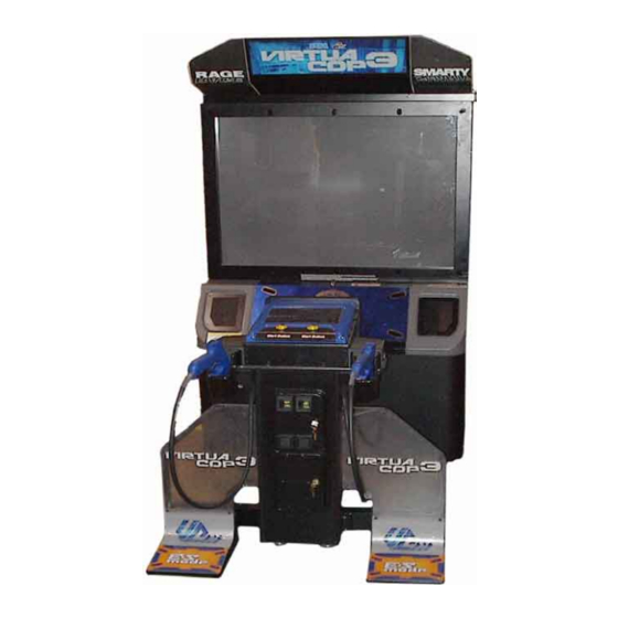
- Page 17 4. NAME OF PARTS BILLBOARD 50 TYPE PROJECTION DISPLAY CONTROLLER CABINET CONTROLLER FENCE L PTV CABINET COIN CHUTE DOOR AC UNIT CASHBOX DOOR FENCE R FOOT PEDAL Note: Actual Unit may differ from image. FIG. 4 TABLE 4 Width × Depth × Height Weight 44.88 in ×...
- Page 18 5. ACCESSORIES When transporting the machine, make sure that the following parts are supplied. TABLE 5 a ACCESSORIES DESCRIPTION KEY MASTER OWNERS MANUAL 220-5576 (2) Part No. Qty. 999-1769(1) For opening/closing For the CASHBOX DOOR Note the doors Figures NOTE: Parts not labeled with part numbers are as yet unregistered or cannot be registered.
- Page 19 HOW TO USE THE CHIHIRO BOARD CARTON BOX STOP Replacement or repair of the Game Board (Chihiro) for this product should be undertaken at the appropriate repair center. Be sure to follow the specifications be- IMPORTANT! low when requesting repairs/sending the board to the repair center. Not following the specifications may result in the board not being accepted or in extra charges being made.
- Page 20 Key Chip Filter Board Plastic bag Top surface cushioning material Corrugated cardboard Chihiro Board AVIP cable Bottom surface cushioning ma t Handles Three honeycomb buffers FIG. 5 a FIG. 5 b www.seuservice.com...
- Page 21 HOW TO USE THE CARTON BOX (GD-ROM DRIVE) STOP When you want to order for replacing or repairing service of the GD-ROM drive that is used by the product, pack it in a carton box as instructed below, and then IMPORTANT! deliver the carton box to a service agent.
- Page 22 6. ASSEMBLING AND INSTALLATION Perform assembly work by following the procedure herein stated. Failing to comply with the instructions can cause electric shock hazard. WARNING! Perform assembling as per this manual. Since this is a complex machine, erroneous assembling can cause an electric shock, machine damage and or not functioning as per specified performance.
- Page 23 When carrying out the assembling and installation, follow the following 9-item sequence. ASSEMBLING THE PTV ASSEMBLING THE CABINET INSTALLING THE FOOT PEDAL SECURING IN PLACE(ADJUSTER TUNING) INSTALLING THE GD-ROM DRIVE(SETTING THE GD-ROM DISC) POWER SUPPLY, AND EARTH CONNECTION TURNING POWER ON ASSEMBLING CHECK The master key (accessories) in addition to the tools such as a Phillips type screwdriver, wrench, socket wrench and Ratchet Handle are required for the assembly work.
- Page 24 ASSEMBLING THE PTV By using 2 Flat Head screws, secure the 2 Mask Bracket Uppers to the PTV ceiling. Secure the Mask Bracket Lower to the front of PTV with 4 screws. FLAT HEAD SCREW (2 each) M4×12 MASK BRACKET UPPER MASK BRACKET LOWER TRUSS SCREW (4), black...
- Page 25 Install the Mask to the PTV front. Install the Mask in a manner hooking up to both 2 Mask Bracket Uppers and the Mask Bracket Lower. Simultaneously insert the projections of the Mask into the square holes in the PTV Screen left and right. ...
- Page 26 ASSEMBLING THE CABINET Move the PTV to the rear of the PTV Cabinet. Connect wiring between the PTV and the PTV Cabinet. Connect the Connector. Connect the Connector. There are 4 cord clamps in the PTV front. FIG.
- Page 27 Secure the joining portion of the PTV and the PTV Cabinet with the 4 screws. TRUSS SCREW (4) M5×30, flat washer used. Have two people lift the Billboard and place it on top of the PTV. Place the Billboard so that the two Mask Bracket Uppers attached in Step 1 fit into the rectangular holes in the Billboard base plate, then slide the Billboard toward the PTV screen.
- Page 28 TRUSS SCREW (2ea), black BILLBOARD LID M4×8, flat washer used PHOTO 6. 2 a PHOTO 6. 2 b Having removed the Billboard Lids from both sides, attach the base plate with 2 screws. SCREW (2) M5×16, w/flat & spring washers PHOTO 6.
- Page 29 Attach Wire Covers L (left) and R WIRE COVER L WIRE COVER R (right) to protect the connectors on the right and left sides of the roof of the PTV. The larger wire cover is Wire Cover L and should be at- tached to the 2 connectors.
- Page 30 Move the controller cabinet nearer to the PTV cabinet. Connect the wires between the controller cabinet and the PTV cabinet. Connect the 7 connec- tors. Insert the controller cabinet into a square opening of the PTV cabinet. In this instance, be care- ful not to catch the wires in the cabinets.
- Page 31 INSTALLING THE FOOT PEDAL Attach the pedal and fence to the left and right of the controller cabinet. The foot base and fence have right and left versions; make sure they are aligned correctly before attaching. PEDAL (works for both right and left) PHOTO 6.
- Page 32 Instructions for attaching the R (right) side are included in this manual. The procedure for at- taching the L (left) side is the same. Attach the foot base to the U- shaped bracket sticking out from the side of the controller cabinet by inserting it from the side.
- Page 33 Attach the pedal to the foot base using 4 hexagonal bolts. Be sure not to tighten the hexagonal bolts completely. Pull wire from the pedal to the foot base and connect the connector on the end of the wire to the connector on the U-shaped bracket.
- Page 34 HEXAGONAL BOLT (2), black M8×35, w/spring washer, large flat washer used PHOTO 6. 3 j BASE HOLE LID Reattach the plate sash as it was before. Securely tighten the 4 hexagonal bolts on the pedal. Attach the base hole lid to the foot base and attach 6 screws.
- Page 35 SECURING IN PLACE (ADJUSTER TUNING) Make sure that all of the adjusters are in contact with the floor. If they are not, the cabinet can move and cause an accident. This product has 6 casters (4 for PTV Cabinet, 2 for CONTROLLER CABINET) and 8 Ad- justers (4 for PTV Cabinet, 4 for CONTROLLER CABINET).
- Page 36 INSTALLING THE GD-ROM DRIVE (SETTING THE GD-ROM DISC) Carefully handle the GD-ROM drive so as not to contaminate the disc and the readout lens with stains and dust particles. Do not continue to use the scratched GD-ROM disc. The scratched GD-ROM disc may cause the system to malfunction.
- Page 37 Use the 4 tapping screws to fix the GD-ROM drive bracket onto the GD-ROM drive. Be careful about a fixing direction. TAPPING SCREW (4) 4×8 FIG. 6. 6 a Remove the 1 truss head screw that fixes the GD-ROM drive lid (DISC LID).
- Page 38 Set the GD-ROM disc onto the GD-ROM drive with its labeled side facing upward. Return the lid to its original place, and fix it with 1 truss head screw. Be careful not to fasten the screw too tightly. PHOTO 6.
- Page 39 Unclamp the clamp on the upper right of the ASSY MAIN BD and disconnect the USB connec- tor from the connect board. Unclamp. USB CONNECTOR CONNECT BOARD PHOTO 6. 6 f Disconnect 7 connectors. CONNECTOR (7) PHOTO 6. 6 g ...
- Page 40 Remove the 2 screws that fix the ASSY MAIN BD's base (a wooden base). Take out the ASSY MAIN BD from the PTV cabinet. Be careful not to damage the wires in this instance. SCREW (2) M5×35, w/spring washer, flat washer used. GD-ROM DRIVE dirve is installed here.
- Page 41 Insert both the GD cable connector (for data communication) and the power cord connector (JST NH6P) into the GD-ROM drive. Be careful about an inserting direction in this instance. Make sure that the connectors are inserted firmly and completely. POWER CORD CONNECTOR GD CABLE CONNECTOR PHOTO 6.
- Page 42 Affix the enclosed stickers to the Game Board. Affix the 843- **** D-02 sticker to the Main Board and the 843- **** B sticker to the Media Board. Place the both stickers on top of the stick- ers already affixed. MEDIA BOARD KEY CHIP MAIN BOARD...
- Page 43 POWER SUPPLY, AND EARTH CONNECTION Be sure to independently use the power supply socket outlet equipped with an Earth Leakage Breaker. Using a power supply without an Earth Leakage WARNING! Breaker can cause a fire when electric leakage occurs. ...
- Page 44 Connect one end of the earth wire to the Connect the Earth Wire AC Unit earth terminal, and the other to the Earth Terminal. end to the indoor earth terminal. The AC Unit earth terminal has a Bolt and Nut combination.
- Page 45 TURNING POWER ON Turn on the AC unit's main switch to connect the power. When the power is connected, the fluo- rescent light in the billboard becomes on. A few seconds later a system startup screen appears and then an advertising screen (plying for a player screen) appears. Time until displaying an advertising screen is not constant;...
- Page 46 ASSEMBLING CHECK In the TEST MODE, ensure that the assembly has been made correctly and IC BD. is satis- factory (refer to Section 9). In the test mode, perform the following test: MEMORY TEST When "MEDIA BOARD TEST" is selected from the System Test Mode Menu Screen the Game Board memory is automatically tested.
- Page 47 C.R.T. TEST ������������������C.R.T.�TEST��1/2 In the TEST mode menu, selecting C.R.T. TEST allows the screen (on which the pro- �����1����������������������������������32 jector is tested) to be displayed. Although RED the projector adjustments have been made at the time of shipment from the factory, GREEN...
- Page 48 OUTPUT TEST Select OUTPUT TEST from the menu in the test mode to cause the screen (on which each lamp and wiring connections are tested) to appear. Ensure that lamp light up satisfactorily. ����������OUTPUT�TEST ���PLAYER�1�START�LAMP���OFF ���PLAYER�2�START�LAMP���OFF ���PLAYER�1�FOOT�PANEL���OFF ���PLAYER�2�FOOT�PANEL���OFF ���PLAYER�1�BILLBOARD����OFF ���PLAYER�2�BILLBOARD����OFF ->�EXIT ���SELECT�WITH�SERVICE�BUTTON �����AND�PRESS�TEST�BUTTON...
- Page 49 THE MAZE OF THE KINGS, U/R type and DX type THE HOUSE OF THE DEAD 3, U/R type and DX type VIRTUA COP 3, U/R type and DX type Disconnect the power. Remove the 2 truss head screws that fix the PTV cabinet lid upper, and unlock.
- Page 50 7. PRECAUTIONS TO BE HEEDED WHEN MOVING THE MACHINE When moving the machine, be sure to pull out the plug from the power sup- ply. Moving the machine with the plug as is inserted can cause the power WARNING! cord to be damaged and could result in a fire and or electric shock.
- Page 51 Do not push PTV from the back. Pushing the PTV from the back can cause the PTV to fall down. Push it from the side. Have caster make contact with the floor. FIG. 7 a GRIP PORTION When transporting the product in places with steps or step-like differences in grade, disassemble into each...
- Page 52 8. GAME CONTENTS The following explanations apply to the case the product is functioning satisfactorily. Should there be any moves different from the following contents, some sort of faults may have occurred. Immediately look into the cause of the fault and eliminate the cause thereof to ensure satisfactory operation.
- Page 53 The Main Characters Virtua Cop 3 has two main characters, RAGE (1P) and SMARTY (2P). JANET appears as an allied character during the game but cannot be controlled. 1P Character: RAGE Strong as an ox and just as uncontrollable, this hothead tends to act before he thinks.
- Page 54 Playing Virtua Cop 3 A) Start a New Game Press the START button to begin a new game. Mission Select follows. B) Calibrating at the Start of the Game The availability of calibration at the start of each game may be set in Test Mode. The following applies when calibration on demand is enabled.
- Page 55 III Bullets Left/Reload Shows bullets remaining in current gun. Shoot the gun away from the screen to reload your weapon. IV Weapon Palette, Weapon Change The player starts out with a Guardian II (10-round magazine, infinite reloads). Defeat special enemies and destroy background objects to get special weapons. Acquiring a special weapon will add a second weapon to the Weapon Palette.
- Page 56 F) ES Attack (Exceeding Sense Attack) ES Attack begins automatically in certain scenes. ES Attack displays special targeting sights that show points of particular vulnerability for a limited time. Speed and accuracy are essential. Hit all the targeted areas within the time given to clear the ES Attack. The outcome of an ES Attack affects the rest of the game's story.
- Page 57 9. EXPLANATION OF TEST AND DATA DISPLAY By operating the switch unit, periodically perform the tests and data check. When installing the machine initially or collecting cash, or when the machine does not function correctly, perform checking in accordance with the explanations given in this section. The following shows tests and modes that should be utilized as applicable.
- Page 58 9-1 SWITCH UNIT AND COIN METER Never touch places other than those specified. Touching places not specified can cause electric shock and short circuit accidents. WARNING! STOP Adjust the sound to the optimum volume, taking into consideration the environmental requirements of the installation location. IMPORTANT! ...
- Page 59 SYSTEM TEST MODE STOP Any settings that are changed by users during TEST MODE are saved upon exiting TEST MODE with the EXIT command in the SYSTEM MENU. If the IMPORTANT! unit is powered off prior to exiting, changes to settings will not take effect. ...
- Page 60 MEDIA BOARD TEST STOP Powering off the system during the MEDIA BOARD TEST with a DIMM BOARD will erase the game programme data. It may be necessary to reload the IMPORTANT! data. Always wait for the test to complete before attempting to exit. MEDIA BOARD TEST is used to check the memory and IC on the MEDIA BOARD connected to the Chihiro.
- Page 61 SYSTEM INFORMATION Use SYSTEM INFORMATION to check version and other information for system programmes. Screens may differ depending on the type of MEDIA BOARD connected to the unit. The following is the SYSTEM INFORMATION screen for a unit with a DIMM BOARD. ����SYSTEM�INFORMATION ��MAIN�BOARD ����REGION������������****...
- Page 62 JVS TEST JVS TEST is used to verify the specs of the I/O BOARD connected to the Chihiro and to run input tests. I/O BOARD specs are displayed initially. Screens may differ depending on the type of I/O BOARD connected to the unit. �����������JVS�TEST ����������INPUT�TEST ����������NEXT�NODE...
- Page 63 INPUT TEST Screen ��������������JVS�TEST �������������INPUT�TEST ����NODE�������1/1 ������SYSTEM�����00 ������PLAYER�1���0000 ������PLAYER�2���0000 ������COIN�1�����0000 ������COIN�2�����0000 ������ANALOG�1���0000 ������ANALOG�2���0000 ������ANALOG�3���0000 ������ANALOG�4���0000 ������ANALOG�5���0000 ������ANALOG�6���0000 ������ANALOG�7���0000 ������ANALOG�8���0000 PRESS�TEST�AND�SERVICE�BUTTON�TO�EXIT On-screen values change according to the input from switches and the volume. SYSTEM, PLAYER Values change with input from control panel/other switches. COIN Increases with input from the COIN SWITCH.
- Page 64 SOUND TEST Use SOUND TEST to test sound output and to select the stereo/mono/surround setting. ��������SOUND�TEST ��OUTPUT�TYPE�������STEREO ��RIGHT�SPEAKER�����OFF ��LEFT��SPEAKER�����OFF →EXIT SELECT�WITH�SERVICE�BUTTON ��AND�PRESS�TEST�BUTTON Use the SERVICE Button to move the cursor to the desired test item. Press the TEST Button to enter the selected item. OUTPUT TYPE(STEREO, MONO, SURROUND) Select the sound output from the I/O PANEL audio output interface setting among STEREO, MONO and SURROUND.
- Page 65 C.R.T. TEST Use the C.R.T. TEST to adjust monitor colours and verify screen size. COLOUR CHECK Screen Monitor COLOUR CHECK screen is displayed initially. Each of the colours (red, green and blue) is darkest at the far left and gets progressively lighter (32 steps) towards the right.
- Page 66 COIN ASSIGNMENTS Use COIN ASSIGNMENTS to set the credit rate for each coin inserted. Use the SERVICE Button to move the cursor to the desired test item. Press the TEST Button to change the setting or to open the detailed settings. ...
- Page 67 COIN TO CREDIT RATE Set the CREDIT RATE for each coin inserted. The "X COIN(S) COUNT AS Y CREDIT(S)" setting indicates that "Inserting X coins equals Y credits". Set this to "FREE PLAY" to allow game play without credits. When (A) COIN CHUTE TYPE is set to "COMMON", COIN CHUTE #2 settings are restricted to some extent by the settings for COIN CHUTE #1.
- Page 68 GAME COST SETTING Use this mode to set the number of credits required to start a game. Screens may differ depending on the game. ���������COIN�ASSIGNMENTS ���������GAME�COST�SETTING ��1�CREDIT(S)�TO�START ��1�CREDIT(S)�TO�CONTINUE →EXIT ����SELECT�WITH�SERVICE�BUTTON ������AND�PRESS�TEST�BUTTON Set the number of credits required to start a game. Set the number of credits required to continue a game.
- Page 69 CLOCK SETTING Use CLOCK SETTING to set the Chihiro internal clock. ������CLOCK�SETTING 20XX/XX/XX(XXX)��XX:XX:XX ���������YEAR ���������MONTH ���������DAY ���������HOUR ���������MINUTE �������→EXIT SELECT�WITH�SERVICE�BUTTON ��AND�PRESS�TEST�BUTTON Use the SERVICE Button to move the cursor to the item to be set. Move the cursor to the desired item and press the TEST Button to increase values. The max value for YEAR is "2099";...
- Page 70 NETWORK SETTING (CORE) Use the LAN PORT attached to the Main Board, and carry out the settings necessary for network communication. Note: This function is not available with this product. ����NETWORK�SETTING�(CORE) ->REMOTE(C)�������ENABLE ��IP�ADDRESS(C) ����---.---.---.--- ��SUBNET�MASK(C) ����---.---.---.--- ��GATE�WAY(C) ����---.---.---.--- ��PRIMARY�DNS(C) ����---.---.---.--- ��EXIT ����CURRENT�************ ������***.***.***.***...
- Page 71 NETWORK SETTING (MEDIA) Use NETWORK SETTING to establish and test network connections. This is only displayed the following error message screen. This game does not support network communication connections. ����NETWORK�SETTING(MEDIA) �����COMMUNICATION�ERROR www.seuservice.com...
- Page 72 GAME TEST MODE STOP When changing the game configuration, changes will not take effect until the Game Test Mode has been completed. Be sure to exit the Game Test Mode properly after IMPORTANT! configuration changes. Select ENTER GAME TEST from the System Menu screen to display the Game Test Menu screen as follows.
- Page 73 A. INPUT TEST Select INPUT TEST to display the following screen and check the status of input devices. This test should be used periodically to check that each input device is functioning correctly. ��������������INPUT�TEST ���������PLAYER������1������2 ���������TRIGGER����OFF����OFF ���������CHANGE�����OFF����OFF ���������PEDAL������OFF����OFF ���������GUN-X������00H����00H ���������GUN-Y������00H����00H ���������SCREEN������IN�����IN ���������START������OFF����OFF ���������SERVICE��������OFF...
- Page 74 B. OUTPUT TEST Select OUTPUT TEST to display the following screen and check the status of each lamp. This test should be used periodically to check that the lamps are functioning correctly. Press the SERVICE Button to move the cursor and the TEST Button to select. Displays ON when selected.
- Page 75 C. GAME ASSIGNMENTS Select GAME ASSIGNMENTS to display the current game settings and make changes. �����GAME�ASSIGNMENTS ���DIFFICULTY������NORMAL ���LIFT������������3 ���COLLISION�������3 ���GUN�LOOSENESS���5 ���CALIBRATION�����OFF ���ADVERTISE�SOUND�OFF ���CABINET�TYPE����DELUXE ->�EXIT SELECT�WITH�SERVICE�BUTTON ��AND�PRESS�TEST�BUTTON FIG. 9. 3 c GAME ASSIGNMENTS screen Perform the following settings for each item. ...
- Page 76 D. GUN ADJUSTMENT Select GUN ADJUSTMENT to display the following screen. This screen allows you to adjust the gun using the five calibration targets (TOP, LEFT, CENTER, RIGHT, BOTTOM). Use each target to calibrate as follows. Use the standard gun controller, carefully aim at the correct target and pull the trigger to calibrate the value.
- Page 77 Details for each item are as follows. TOP x y: Set the TOP value. The number on the left (x) is the horizontal component, and the number on the right (y) is the vertical component. Aim the controller at the TOP target (circle) and pull the trigger to set the value.
- Page 78 E. BOOKKEEPING Select BOOKKEEPING on the Game Test Menu screen to display the three screens of operating status data. Press the TEST Button on the BOOKKEEPING 1/3 and BOOKKEEPING 2/3 screens to move to the second and third (BOOKKEEPING 3/3) screens. Press the TEST Button in the third screen to return to the Game Test Menu screen.
- Page 79 ���������BOOKKEEPING��2/3 NUMBER�OF�GAMES����������������3 NUMBER�OF�GAME�START�����������3 NUMBER�OF�CONTINUE�������������0 NUMBER�OF�JOIN�GAMES�����������0 TOTAL�TIME�����������0D�0H10M49S PLAY�TIME������������0D�0H�1M55S LONGEST�PLAY�TIME�������0H�1M24S SHORTEST�PLAY�TIME������0H�0M14S AVERAGE�PLAY�TIME�������0H�0M38S ��PRESS�TEST�BUTTON�TO�CONTINUE FIG. 9. 3 e b BOOKKEEPING 2/3 screen The display items for the screen (Page 2 of 3) are as follows. NUMBER OF GAMES: The total number of games played by 1P and 2P. ...
- Page 80 F. BACKUP DATA CLEAR Select BACKUP DETA CLEAR to clear the contents of BOOKKEEPING, ranking data and coin/credit data. ����BACKUP�DATA�CLEAR �������YES�(CLEAR) ����->�NO��(CANCEL) SELECT�WITH�SERVICE�BUTTON ��AND�PRESS�TEST�BUTTON FIG. 9. 3 f BACKUP DATA CLEAR screen To clear data, use the SERVICE Button to move the cursor to YES (CLEAR) and then press the TEST Button.
- Page 81 10. CONTROL UNIT (GUN CONTROLLER) In order to prevent an electric shock and short circuit, be sure to turn power off before performing work by touching the interior parts of the product. WARNING! Be careful not to damage the wires. Damaged wires may cause electric shock or short circuit or present a fire risk.
- Page 82 REPLACING THE MICROSWITCH To replace the Gun Controller's internal components, first separate the left shell (Cover L) and right shell (Cover R). The controller's internal components are mounted on the right shell, so work with the gun lying on its right side. To replace the weapon change button microswitch, first remove the weapon change button from the right shell.
- Page 83 Remove the trigger microswitch from the right shell. MICROSWITCH 509-5080 Remove the soldering and detach the microswitch. PHOTO 10 c Remove the weapon change button from the right shell. WEAPON CHANGE BUTTON PHOTO 10 d Remove the spring from the right shell.
- Page 84 Remove 1 screw and detach the microswitch (with SW bracket attached) from the right shell. SCREW (1) M3×8, w/flat & spring washers PHOTO 10 f Disconnect the microswitch wire connector. Disconnect the connector. PHOTO 10 g Remove the 2 screws and remove the SW bracket from the microswitch. SCREW (2) M2.3×10, w/flat &...
- Page 85 Remove the soldering and extract the microswitch. Solder a new microswitch and rebuild the gun controller. Make sure that the wire in the right shell (Cover R) and the connector are wired as in the diagram before reattaching the left shell (Cover L) to the right shell.
- Page 86 REPLACING THE SENSOR UNIT Follow the first 3 steps of "Replacing the Microswitch" to remove the left shell. Detach the connector and pull out the sensor unit. Detach the connector. SENSOR UNIT JPT-2030 PHOTO 10 i www.seuservice.com...
- Page 87 PROJECTOR Since the Projector has been adjusted at the time of shipment, avoid making further adjustments without good reason. CAUTION! STOP The Projector is subject to color deviation due to Convergence deviation caused by the geomagnetism at the installation location and peripheral magnetic field. IMPORTANT! After the installation of machine, and before commencing operation, check for Convergence deviation and if deviated, make adjustments.
- Page 88 11-2 PROJECTOR ADJUSTMENT SETTING THE INTERFACE In this product, set to INPUT LEVEL: 0.7 V and IMPEDANCE: 75Ω. Failure to observe this can cause CRT membrane to burn or Shutdown device to function resulting in power off. The Projector's Connector Panel contains the Interface setting SW. WINNER AC IN LAMP...
- Page 89 AUTOMATIC COLOR MATCHING The Projector may be subject to color deviations affected by earth magnetism, the building steel frames, etc. When the Projector is initially installed or the Projector's installation position is changed, have the color matching performed automatically. (1) Keep pressing the P button (red) for approximately 3 seconds to have the ensuing movements performed automatically.
- Page 90 ADJUSTING THE SCREEN BRIGHTNESS Although the on-screen picture quality has been adjusted at the time of shipment from the factory, readjustment can be made if desired. When the Game Board is replaced, readjustment may be necessary. Changing the BRIGHTNESS causes the brightness of the on-screen images of black portions to be changed.
- Page 91 ADJUSTING THE ON-SCREEN DISPLAY POSITION Although the on-screen display position (H. POSI, V. POSI) has been adjusted at the time of shipment from the factory, readjustment can be made if desired. When the Game Board is replaced, readjustments may be necessary. ...
- Page 92 ADJUSTING THE SCREEN SIZE Although the on-screen size (H. SIZE, V. SIZE) has been adjusted at the time of shipment from the factory, readjustment can be made if desired. When the Game Board is replaced, readjustments may be necessary. ...
- Page 93 CONVERGENCE ADJUSTMENT (manual color matching) To avoid circuitry malfunctioning due to electrical load increase, never utilize CONVERGENCE ADJUSTMENT (Line Convergence Adjustment in particular) CAUTION! for adjusting screen size changes. There is no means to restore the Convergence Adjustment data once stored, to its original state.
- Page 94 STATIC CONVERGENCE ADJUSTMENT In the STATIC CONVERGENCE adjustment, each of red and blue images is comprehensively moved to and superimposed on the green color. If automatic color matching function is not sufficiently satisfactory, perform this adjustment. Be sure to perform automatic color matching before starting the above adjustment.
- Page 95 POINT CONVERGENCE ADJUSTMENT In the POINT CONVERGENCE adjustment, each of red, green and blue images is partially moved for color matching. The adjustment may be necessary when the Game Board is replaced or changed, or screen size is changed. Be sure to perform automatic color matching before starting the adjustment.
- Page 96 LINE CONVERGENCE ADJUSTMENT In the LINE CONVERGENCE adjustment, the adjustment point of the column line (vertical) or row line (horizontal) is comprehensively moved for color matching. It is convenient to utilize this adjustment when the color of the column line or row line is uniformly deviated. (1) Keep pressing the TEST button for approximately 3 seconds.
- Page 97 12. COIN SELECTOR HANDLING THE COIN JAM If the coin is not rejected when the REJECT button is pressed, open the coin chute door and open the selector gate. After removing the jammed coin, put a normal coin in and check to see that the selector correctly functions.
- Page 98 COIN DOOR www.seuservice.com...
- Page 99 13. REPLACING THE FLUORESCENT LAMP/OTHER LAMPS When performing work, be sure to turn power off. Working with power on can cause electric shock and short circuit hazards. CAUTION! The Fluorescent Lamp, when it gets hot, can cause burn. Be very careful when replacing the Fluorescent Lamp.
- Page 100 LAMP REPLACEMENT Take out the 8 screws and remove Control Panel DX. CONTROL PANEL DX TRUSS SCREW (8), chrome M4×8, flat washer used. FIG. 13 b Hold both sides of the switch portion with fingers and pull out from the button's base portion. At this time, be careful so as not to damage the wiring connected to the switch.
- Page 101 14. PERIODIC INSPECTION TABLE The items listed below require periodic check and maintenance to retain the performance of this machine and to ensure safe business operation. When handling the control unit, the player will be in direct contact with it . In order to always al- low the player to enjoy the game, be sure to clean it regularly.
- Page 102 15. TROUBLESHOOTING 15-1 PROBLEMS NOT INVOLVING THE GAME BOARD In case a problem occurs, first check wiring connector connections. In order to prevent electric shock and short circuit, be sure to turn power off before performing work. Be careful not to damage the wires. Damaged wires may cause electric shock or short circuit or present a fire risk.
- Page 103 TABLE 15. 1 b PROBLEMS CAUSE COUNTERMEASURES No sound is emit- Sound volume adjustment is not ap- Adjust sound volume ted. propriate. Board and Amplifier malfunctioning. Perform the sound test and confirm Control Unit Due to environmental changes, etc., Perform sighting adjustment in the test sighting is not sighting became inappropriate.
- Page 104 REPLACING THE LED BD In case two of LED's do not emit light, failure and malfunctioning may be considered. Replace in the following procedure. When removing surface soils, also use the following procedure. If the light emission from the 2 LED's can not be seen, replace. FIG.
- Page 105 15-2 ERROR CODES If an error code is displayed, have a Location's Maintenance Man or Service- man resolve it. If someone without specialized or technical knowledge attempts WARNING! to rectify the problem, electric shock, short circuits or fire may result. If there is no store maintenance person or technician available, turn the power OFF im- mediately, and contact your retailer or the office listed in this manual.
- Page 106 Error 11 [DISPLAY] Error 11 JVS I/O board is not connected to main board. [CAUSE] (1) I/O BOARD is not connected. (2) Unreliable connection between MAIN BOARD and I/O BOARD. [COUNTERMEASURES] (1) Connect the I/O BOARD to the MAIN BOARD. Verify that the power cable is connected to I/O BOARD.
- Page 107 Error 25 [DISPLAY] Error 25 Cannot access GD-ROM drive. [CAUSE] (1) Unable to access GD-ROM DRIVE. (2) The GD-ROM DRIVE cover is open. [COUNTERMEASURES] (1) Verify that the GD CABLE and the power cable are properly connected to the GD-ROM DRIVE. (2) Close the GD-ROM cover securely.
- Page 108 16. GAME BOARD In order to prevent electric shock and short circuit hazards, be sure to turn power off before performing work. Be careful not to damage the wires. Damaged wires may cause electric shock or short circuit or present a fire risk. ...
- Page 109 Disconnect all connectors from the ASSY MAIN BD. There are 3 connectors on the left side. Unclamp the cord clamp on the upper right and disconnect the USB connector attached to the connect board. CONNECTOR (3) PHOTO 16. 1 b Remove the cord clamp.
- Page 110 Loosen the screws on either side of the D-SUB connector connected to the Chihiro Board and disconnect. D-SUB CONNECTOR PHOTO 16. 1 e SCREW (2) Remove the 2 screws that fasten M5×35, w/spring washer, flat washer used. the ASSY MAIN BD wooden Base PHOTO 16.
- Page 111 Work with the ASSY MAIN BD set on a level surface. PHOTO 16. 1 h Unplug all connectors connected to the Chihiro Board. Unplug the GD Cable connector on the side of the Media Board on the upper part of the Chihiro Board.
- Page 112 Remove the 4 screws and remove the Chihiro Board from the Base. SCREW (4) M4×16, w/flat & spring washers PHOTO 16. 1 k www.seuservice.com...
- Page 113 REMOVING THE GD-ROM DRIVE Take out the ASSY MAIN BD from the PTV cabinet; and then remove the GD-ROM drive from the ASSY MAIN BD as follows: Carry out the "Removing the Game Board" procedures and remove the ASSY MAIN BD from the cabinet.
- Page 114 16-2 COMPOSITION OF THE GAME BOARD STOP Once the Chihiro Board has the Key Chip inserted, it is this product's specialized Game Board. IMPORTANT! ASSY CASE BOX VCT EXP(843-0003D-02) FIG. 16. 2 a DIP SW SETTING Use this product with the DIP SW settings shown in the figure below. FIG.
- Page 115 16-3 REPLACING THE MAIN BOARD BATTERY To prevent overheating, explosion, or fire: • Do not recharge, disassemble, heat, incinerate, or short the battery. WARNING! • Do not allow the battery to come into direct contact with metallic objects or other batteries. •...
- Page 116 16-4 REPLACING THE MEDIA BOARD BATTERY PACK Prohibitions and Cautions to Handle the Battery Pack Be careful when handling the battery pack. We bear no responsibility for problems caused by handling clearly contrary to the content of this manual. Do not disassemble the battery pack and the batteries. If you should fail to observe this instruction, the internal wires and/or WARNING! protective devices may be damaged;...
- Page 117 Do not tightly seal the battery pack when installing it onto an external device. Flammable gas is generated from the battery when its safety mechanism has WARNING! functioned. If you should fail to observe the above-described instruction, sparks from motors, switches, etc. may cause the gas to fire. Therefore, install the battery pack so that the gas can be quickly released from the external device.
- Page 118 If the GD-ROM read time becomes excessively long, it is likely that the Media Board battery pack life if running low. No battery pack charger is available. Follow the procedure to replace the battery pack. Remove 4 screws from the upper face of the board. ...
- Page 119 17. DESIGN RELATED PARTS ITEM NO. PART NO. DESCRIPTION NOTE VCT-0525 BILLBOARD PLATE VCT VCT-0526 BILLBOARD PLATE L VCT VCT-0527 BILLBOARD PLATE R VCT VCT-0531 DECAL BILLBOARD VCT VCT--0511 DECAL PTV SIDE LorR 999-1770 CONTROL PANEL INSTRUCTIONS 999-1771 CONTROL PANEL START DECAL 999-1772 DECAL CONTROL PANEL L 999-1773...
- Page 120 18. PARTS LIST 1 TOP ASSY VCT DX D-1/2 www.seuservice.com...
- Page 121 1 TOP ASSY VCT DX D-2/2 ITEM NO. PART NO. DESCRIPTION NOTE VCT-0500 ASSY PTV VCT-1000 ASSY PTV CABINET DX VCT-1150 ASSY FENCE L VCT-1160 ASSY FENCE R SPY-0001 JOINT BRKT L SPY-0002 JOINT BRKT R JEY-0005 DENOMI PLATE SGM-4346 POLY COVER 1200×1200×1300 SGM-4426 POLY COVER 800×750×900...
- Page 122 www.seuservice.com...
- Page 123 2 ASSY PTV (VCT-0500) D-1/2 www.seuservice.com...
- Page 124 2 ASSY PTV (VCT-0500) D-2/2 ITEM NO. PART NO. DESCRIPTION NOTE VCT-0510 PTV W/STICKER VCT DX VCT-0520 ASSY BILLBOARD DX SPY-0530 ASSY MASK HOD-1101 PTV HOLDER FRQ-1114 MASK BRKT UPPER SMB-1501 MASK BRKT LOWER VCT-0501 WIRE COVER L VCT-0502 WIRE COVER R 000-T00520-0B M SCR TH BLK M5×20 000-F00412...
- Page 125 3 PTV W/STICKER VCT DX (VCT-0510) BOTH SIDES ITEM NO. PART NO. DESCRIPTION NOTE VCT-0511 STICKER PTV SIDE 200-5788-31 PROJECTION DSPL T 50TYPE 31K 280-5009-01 CORD CLAMP 21 011-F00310 TAP SCR FH 3×10 www.seuservice.com...
- Page 126 4 ASSY BILLBOARD DX (VCT-0520) D-1/2 www.seuservice.com...
- Page 127 4 ASSY BILLBOARD DX (VCT-0520) D-2/2 ITEM NO. PART NO. DESCRIPTION NOTE VCT-0521 BILLBOARD BOX VCT-0522 BILLBOARD SASH VCT-0523 BILLBOARD LID VCT-0524 BD BASE VCT-0525 BILLBOARD PLATE VCT VCT-0526 BILLBOARD PLATE L VCT VCT-0527 BILLBOARD PLATE R VCT VCT-0528 PLATE HOLDER L VCT-0529 PLATE HOLDER R VCT-0530...
- Page 128 5 ASSY MASK (SPY-0530) ITEM NO. PART NO. DESCRIPTION NOTE SPY-0531 MASK BASE JPT-1082 IR COVER 838-13145-02 LED BD GUN SENSE HOD 280-5008 CORD CLAMP 15 050-U00300 U NUT M3 068-330808-PN FLT WSHR PLASTIC 3.3-8×0.8 050-H00400 HEX NUT M4 060-F00400 FLT WSHR M4 060-S00400 SPR WSHR M4...
- Page 129 6 ASSY CABINET DX (VCT-1000) D-1/2 www.seuservice.com...
- Page 130 6 ASSY CABINET DX (VCT-1000) D-2/2 ITEM NO. PART NO. DESCRIPTION NOTE VCT-1001 ASSY SUB-CABI PTV DX SPY-1050 AC UNIT VCT-1060 ASSY LID UPPER VCT-1070 ASSY LID LOWER VCT-4000 ASSY MAIN BD FRQ-1071 SPEAKER BRKT VCT-1003 SPEAKER COVER L VCT-1004 SPEAKER COVER R FRQ-1007 SPEAKER NET L...
- Page 131 7 ASSY SUB-CABI PTV DX (VCT-1001) D-1/2 www.seuservice.com...
- Page 132 7 ASSY SUB-CABI PTV DX (VCT-1001) D-2/2 ITEM NO. PART NO. DESCRIPTION NOTE FRQ-1002X PTV CABINET FRQ-1009 LEG CASTER BRKT A SPY-1005 HOLDER PLATE FRQ-1012 LEG CASTER BRKT B SPY-1006 HOLDER BRKT L SPY-1007 HOLDER BRKT R 117-5284 PLATE 6-80 BLACK HOD-1003 LOCKING BRKT HOD SPY-1080...
- Page 133 8 FAN UNIT (SPY-1080) CONNECTOR POSITION ITEM NO. PART NO. DESCRIPTION NOTE SPY-1081 FAN BRKT 260-0011-02 AXIAL FLOW FAN AC100V 50-60HZ 601-8543 FAN GUARD 000-P00312-W M SCR PH W/FS M3×12 www.seuservice.com...
- Page 134 10 ASSY LID UPPER (VCT-1060) ITEM NO. PART NO. DESCRIPTION NOTE SPY-1061 LID UPPER VCT-1061 STICKER LID UPPER TH-1015 LOCKING TONGUE 220-5575 CAM LOCK MASTER W/O KEY www.seuservice.com...
- Page 135 11 ASSY LID LOWER (VCT-1070) ITEM NO. PART NO. DESCRIPTION NOTE VCT-1071 LID LOWER SPY-1071 LID BRKT VCT-1072 BD BASE 280-5009-01 CORD CLAMP 21 838-13143-08 IC BD GUN SENSE SPY 838-13143-10 IC BD GUN SENSE SPY EXTRA 280-5256 TIE BASE TMIS4 050-F00400 FLG NUT M4 011-F00310...
- Page 136 12 ASSY MAIN BD (VCT-4000) D-1/2 www.seuservice.com...
- Page 137 12 ASSY MAIN BD (VCT-4000) D-2/2 ITEM NO. PART NO. DESCRIPTION NOTE VCT-4001 MAIN BASE 843-0001D-22 ASSY CASE BOX COM DIMM EXP 839-0979 CONDENSER BD 839-1221 RGB LED DECODER BD 839-1176-01 CONN BD JVS 400-5443 SW REGU FOR CHIHIRO 610-0674 POWER PROTECT UNIT FOR CHIHIRO 837-13551-92 I/O CONTROL BD FOR JVS...
- Page 138 13 ASSY CONTROLLER CABINET (VCT-1100) D-1/2 www.seuservice.com...
- Page 139 13 ASSY CONTROLLER CABINET (VCT-1100) D-2/2 ITEM NO. PART NO. DESCRIPTION NOTE VCT-1101 ASSY SUB-CABI CONTROLLER 999-XXXX CONTROL PANEL COVER VCT-2100 CONTROL UNIT SPY-1170 SW UNIT HOD-1590 METER UNIT CPT-1017 CABLE CLAMP 253-5366 CASH BOX 000-T00416-0C M SCR TH CRM M4×16 000-T00430-0C M SCR TH CRM M4×30 000-P00416-W...
- Page 140 14 ASSY SUB-CABI CONTROLLER (VCT-1101) D-1/3 www.seuservice.com...
- Page 141 14 ASSY SUB-CABI CONTROLLER (VCT-1101) D-2/3 ITEM NO. PART NO. DESCRIPTION NOTE VCT-1102 CONTROLLER CABINET SPY-1103 JOINT NUT PLATE SPY-1104 PLATE 8-70 SPY-1105 JOINT PART LID VCT-1104 CONN PNL BRKT 105-5106 CASH BOX COVER 105-5107 CHUTE 105-5188 HOLE COVER DP-1167 TNG LKG 105-5170 LOCK BRACKET S...
- Page 142 14 ASSY SUB-CABI CONTROLLER (VCT-1101) D-3/3 ITEM NO. PART NO. DESCRIPTION NOTE 600-6455-02 WIRE HARN C.C DOOR SINGLE SPY-60014 WH TOWER EXT 2 SPY-60015 WH START EXT 2 SPY-60016X WH RECIEVER EXT 2 SPY-60022 WH EARTH CTRL CABI 600-6972-0280 WIRE HARN EARTH ID5 0280MM 600-6972-0120 WIRE HARN EARTH ID5 0120MM 600-6972-0480...
- Page 143 15 ASSY CTRL PANEL DX (VCT-2000) D-1/2 www.seuservice.com...
- Page 144 15 ASSY CTRL PANEL DX (VCT-2000) D-2/2 ITEM NO. PART NO. DESCRIPTION NOTE VCT-2001-01 CTRL PNL ENG 999-1774 VAC FORM CONTROL PANEL 509-5712-01S SW PB W/L 6V YELLOW 280-5009-01 CORD CLAMP 21 280-5275-SR10 CORD CLAMP SR10 HOD-60020 WIRE HARN CONTROL PANEL www.seuservice.com...
- Page 145 16 CONTROL UNIT EXP (VCT-2100-01) D-1/2 www.seuservice.com...
- Page 146 16 CONTROL UNIT EXP (VCT-2100-01) D-2/2 ITEM NO. PART NO. DESCRIPTION NOTE VCT-2101-01 COVER L EXP VCT-2102-01 COVER R EXP VCT-2103-01 HAMMER EXP VCT-2104 TRIGGER VCT-2105 CHANGE BUTTON VCT-2106 SW BRKT VCT-2107 COM SPRING JPT-2030 SENSOR UNIT 125-5124 TORSION SPRING 280-5124-04 NYLON CLAMP NK04 310-5029-D20...
- Page 147 17 SENSOR UNIT (JPT-2030) ITEM NO. PART NO. DESCRIPTION NOTE JPT-2031 SENSOR HOLDER 838-13144 SENSOR BD GUN SENSE 012-P00306 TAP SCR #2 PH 3×6 www.seuservice.com...
- Page 148 18 SW UNIT (SPY-1170) ITEM NO. PART NO. DESCRIPTION NOTE SPY-1171 SW BRKT 421-8126 STICKER SWITCH PANEL 509-5028 SW PB 1M (MIYAMA DS-412R) 220-5754 VOL CONT B5KOHM (RV24YN 15S) 601-0042 KNOB 22 MM 310-5029-F20 SUMI TUBE FF 20MM SPY-60017 WH SW UNIT www.seuservice.com...
- Page 149 19 METER UNIT (HOD-1590) ITEM NO. PART NO. DESCRIPTION NOTE HOD-1591 METER BRKT 421-6591-01 STICKER COIN METER 220-5617-01 MAG CNTR DC5V W/CONN 6P WH 220-5643-01 MAG CNTR DC5V 6P WH MZ-674-D04 www.seuservice.com...
- Page 150 20 ASSY FENCE L (VCT-1150) ITEM NO. PART NO. DESCRIPTION NOTE VCT-1151 FENCE FRAME L VCT-1152 DESIGN PLATE L VCT-1153 GUARD PLATE L FAS-290034 HEX SKT LH CAP SCR STN M5×15 www.seuservice.com...
- Page 151 21 ASSY FENCE R (VCT-1160) ITEM NO. PART NO. DESCRIPTION NOTE VCT-1161 FENCE FRAME R VCT-1162 DESIGN PLATE R VCT-1163 GUARD PLATE R FAS-290034 HEX SKT LH CAP SCR STN M5×15 www.seuservice.com...
- Page 152 22 ASSY FOOT PEDAL DX (VCT-1200) D-1/2 www.seuservice.com...
- Page 153 22 ASSY FOOT PEDAL DX (VCT-1200) D-2/2 ITEM NO. PART NO. DESCRIPTION NOTE VCT-1201X PEDAL BASE DX VCT-1202X PEDAL VCT-1203 FOOT PLATE VCT-1204 COM SPRING VCT-1205 SPRING COVER VCT-1206 SHADE PLATE VCT-1207 SENSOR BRKT VCT-1208 WIRE COVER VCT-1209 STOPPER RUBBER VCT-1210 RUBBER CUSHION VCT-1211...
- Page 154 23 ASSY FOOT BASE L (VCT-1300) ITEM NO. PART NO. DESCRIPTION NOTE VCT-1301 FOOT BASE FRAME L 601-5699X LEG ADJUSTER BOLT M16×75 280-5009-01 CORD CLAMP 21 050-H01600-0B HEX NUT BLK M16 www.seuservice.com...
- Page 155 24 ASSY FOOT BASE R (VCT-1310) ITEM NO. PART NO. DESCRIPTION NOTE VCT-1311 FOOT BASE FRAME R 601-5699X LEG ADJUSTER BOLT M16×75 280-5009-01 CORD CLAMP 21 050-H01600-0B HEX NUT BLK M16 www.seuservice.com...
- Page 156 25 ASSY XFMR 100V AREA (SMB-4100) ITEM NO. PART NO. DESCRIPTION NOTE FRQ-4101 PWR SPLY BASE 560-5384 XFMR 100-120V 100V 10A WB 280-5207 HARNESS LUG CC-1005 011-T03512 TAP SCR TH 3.5×12 000-P00516-W M SCR PH W/FS M5×16 SMB-60052 WIRE HARN XFMR IN SMB-60053 WIRE HARN XFMR OUT www.seuservice.com...
- Page 157 25 ASSY XFMR 200V AREA (SMB-4200) ITEM NO. PART NO. DESCRIPTION NOTE FRQ-4101 PWR SPLY BASE 560-5377 PWR XFMR 200-240V 100V10A CE 280-5207 HARNESS LUG CC-1005 011-T03512 TAP SCR TH 3.5×12 000-P00516-W M SCR PH W/FS M5×16 SMB-60052 WIRE HARN XFMR IN SMB-60053 WIRE HARN XFMR OUT www.seuservice.com...
- Page 158 19. WIRE COLOR CODE TABLE THE WIRE COLOR CODE is as follow: PINK SKY BLUE BROWN PURPLE LIGHT GREEN Wires other than those of any of the above 5 single colors will be displayed by 2 alphanumeric characters. BLUE YELLOW GREEN WHITE ORANGE...
- Page 159 Warranty Your new Sega Product is covered for a period of 90 days from the date of shipment. This certifies that the Printed Circuit Boards, Power Supplies and Monitor are to be free of defects in workman- ship or materials under normal operating conditions. This also certifies that all Interactive Control Assemblies are to be free from defects in workmanship and materials under normal operating condi- tions.
- Page 160 SEGA AMUSEMENTS USA, INC.
Need help?
Do you have a question about the VIRTUA COP and is the answer not in the manual?
Questions and answers