Table of Contents
Advertisement
420-0015-00UK
2
nd
Printing
Sega Amusements Europe Limited.
42 Barwell Business Park, Leatherhead Road, Chessington, Surrey, KT9 2NY. United Kingdom.
Telephone: +44 (0) 208 391 8090
Facsimile:
+44 (0) 208 391 8099
email: mailbox@sega.co.uk
Web: http://www.sega-amusements.co.uk
© SEGA
IMPORTANT
• Before using this product, read this manual carefully to understand the
contents herein stated.
• After reading this manual, be sure to keep it near the product or in a
convenient place for easy reference when necessary.
Advertisement
Table of Contents

Related Manuals for Sega Virtua Tennis 4


Summary of Contents for Sega Virtua Tennis 4
- Page 1 420-0015-00UK Printing Sega Amusements Europe Limited. 42 Barwell Business Park, Leatherhead Road, Chessington, Surrey, KT9 2NY. United Kingdom. Telephone: +44 (0) 208 391 8090 Facsimile: +44 (0) 208 391 8099 email: mailbox@sega.co.uk Web: http://www.sega-amusements.co.uk © SEGA IMPORTANT • Before using this product, read this manual carefully to understand the contents herein stated.
- Page 2 BEFORE USING THE PRODUCT, BE SURE TO READ THE FOLLOWING: To maintain safety: To ensure the safe operation of this product, be sure to read the following before usage. The following instructions are intended for the users, operators and the personnel in charge of the operation of the product.
- Page 3 SEGA shall not be held responsible for any accidents, compensation for damage to a third party, resulting from the specifications not designated by SEGA.
-
Page 4: Table Of Contents
TABLE OF CONTENTS HANDLING PRECAUTIONS PRECAUTIONS REGARDING INSTALLATION PRECAUTIONS REGARDING OPERATION PART DESCRIPTIONS ACCESSORIES ASSEMBLY AND INSTALLATION 6-1 INSTALLING THE CABINET 6-2 FIXATION TO SITE 6-3 POWER SUPPLY AND OTHER CONNECTIONS 6-4 TURNING ON THE POWER 6-5 CONFIRMATION OF ASSEMBLY PRECAUTIONS WHEN MOVING THE MACHINE 7-1 PRECAUTIONS WHEN MOVING FROM SITE GAME DESCRIPTION... - Page 5 LAMPS AND LIGHTING 13-1 REPLACING THE BILLBOARD LED BAR 13-2 REPLACING THE HEADER LED BAR 13-3 REPLACING THE LOWER LED BAR PERIODIC INSPECTION TROUBLESHOOTING 15-1 TROUBLESHOOTING (WHEN NO ERROR MESSAGE IS SHOWN) GAME BOARD (RINGEDGE) 16-1 HANDLING PRECAUTIONS 16-2 PARTS DETAILS 16-3 RINGWIDE COMPONENTS 16-4 ERROR CODES DISPLAY 16-5 REPLACING THE BUTTON BATTERY...
- Page 6 This manual is intended to provide detailed descriptions together with all the necessary information covering the general operation of electronic assemblies, electro-mechanicals, servicing control, spare parts, etc. for the product, “Virtua Tennis 4.” This manual is intended for the owners, personnel and managers in charge of operation of the product.
- Page 7 Indicates a warning or caution that, if ignored, may result in the mishandling of the product and cause faulty operation or damage to the product. Sega Amusements Europe Limited. 42 Barwell Business Park, Leatherhead Road, Chessington, Surrey, KT9 2NY. United Kingdom.
- Page 8 Release version numbers are for SEGA's administrative use only. If you require these numbers, please contact the office listed in this manual or the point of purchase for this product.
- Page 9 The WEEE (Waste of Electrical and Electronic Equipment) directive places an obligation on all EU based manufac- turers and importers of Electrical and Electronic Equipment to take back products at the end of their useful life. Sega Amusements Europe Ltd accepts its responsibility to finance the cost of treatment and recovery of redundant WEEE in the United Kingdom in accordance with the specified WEEE recycling requirements.
-
Page 10: Handling Precautions
HANDLING PRECAUTIONS When installing or inspecting the machine, be very careful of the following points and pay attention to ensure that the player can enjoy the game safely. Non-compliance with the following points or inappropriate handling running counter to the cautionary matters herein stated can cause personal injury or damage to the machine. - Page 11 CONCERNING THE STICKER DISPLAY This SEGA product has stickers attached describing the product manufacture No. (Serial No.) and Electrical Specifications. It also has a Sticker describing where to contact for repair and for purchasing parts. When inquiring about or asking for repairs, mention the Serial No. and Name of Machine indicated on the Sticker.
- Page 12 Take care when servicing within these areas. Serial number and Rating plate Electrical Waste Logo WEEE Ringwide Serial Number...
- Page 13 • The operator MUST apply the Epileptiform Seizure Label to this product. Failing to apply this label may result in the player/observer suffering from a photosensitive seizure. Warning the potential player/ observer of this before the start of a game may prevent such accidents. •...
-
Page 14: Precautions Regarding Installation
PRECAUTIONS REGARDING INSTALLATION This product is an indoor game machine. Do not install it outside. Even indoors, avoid installing in places mentioned below so as not to cause a fire, electric shock, injury and/or malfunction. - Places subject to rain or water leakage, or places subject to high humidity in the proximity of an indoor swimming pool and/or shower, etc., or places where a water jet (high pressure washing device) could be used. - Page 15 ● For safe operation, use and operate this product in an area measuring at least 1.16 m (45.6 in) in width and 104 m (55.3 in) in depth. SEGA shall not be held responsible for damage or compensation for damage to a third party, resulting from the failure to observe this instruction.
- Page 16 OPERATION AREA 1.16 m (45.6 in) 0.25 m (9.8 in) 0.25 m (9.8 in) 0.15 m (5.9 in)
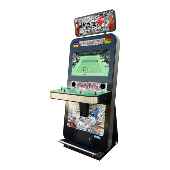
- Page 17 Width 0.86m (33.8in) Depth 0.85m (33.4in) Height 2.13m (83.8in) Weight 140kg Installation space 1166mm x 865mm x 2300mm Monitor Position Applicable resolutions - 640×480 HORIZONTAL - 1280×720 - 1920×1080...
-
Page 18: Precautions Regarding Operation
PRECAUTIONS REGARDING OPERATION To avoid injury and trouble, be sure to pay attention to the behavior of visitors and players. 3-1 BEFORE OPERATION ● To avoid injury, be sure to provide sufficient space by considering the potentially crowded situation at the installation location. Insufficient installation space can cause contact, collisions, and/or trouble between customers. ● During daily cleaning, be sure to check the surface of the control unit and other parts that the player touches with his/her hands for damage, cracks, or loose screws. If a player uses the machine while it is damaged, cracked, or has a loose screw, the player may become injured. - Page 19 ● To ensure maximum safety for the players and the customers, ensure that where the product is operated has sufficient lighting to allow any warnings to be read. Operation under insufficient lighting can cause bodily contact with each other, hitting accident, and/or trouble between customers. ● Check if all of the adjusters are in contact with the surface. If they are not, the cabinet can move and cause an accident. Ensure that the leg adjusters are both correctly adjusted so that the front castors are raised approximately 5mm from the floor surface.
- Page 20 3-2 PAYING ATTENTION TO CUSTOMERS To avoid injury and trouble, be sure to constantly give careful attention to the behavior and manner of the visitors and players. • For safety reasons, do not allow any of the following people to play the game. - Those who have high blood pressure or a heart problem. - Those who have experienced muscle convulsion or loss of consciousness w hen playing video games, etc. - Those who have neck or spinal cord problems. - Those who are intoxicated or under the influence of drugs. - Pregnant women. - Those who are not in good health.
-
Page 21: Part Descriptions
PART DESCRIPTIONS Assembly Billboard Assy LCD Display Speakers Service Door (control Panel) Cash Door Foot Rest Coin Insert Assy Control Panel Rear Service Panels AC Unit... -
Page 22: Accessories
ACCESSORIES Confirm that the accessories listed in the table below are present when setting up the product. Accessories marked “Spare” in the note column are consumable items but included as spares. Part name / number Diagram / Use etc. Quantity Owners Manual Key Master Key (for cash box) -
Page 23: Assembly And Installation
ASSEMBLY AND INSTALLATION • Perform assembly work by following the procedure herein stated. Failure to comply with the instructions can cause electric shock. • Perform assembly as per this manual. Since this is a complex machine, incorrect assembling can cause an electric shock, machine damage and/or improper functioning as per specified performance. • When assembling, more than one person is required. Depending on the assembly work, there are some cases in which working by one person alone can cause personal injury or parts damage. • Ensure that connectors are properly connected. Improper connections can cause electric shock. • Be careful not to damage the wires. Damaged wires may cause electric shock or short circuit or present a risk of fire. • Do not unnecessarily push the display screen. • This work should be carried out by site maintenance personnel or other qualified professionals. Work performed by non-technical personnel can cause a severe accident such as electric shock. Failing to comply with this instruction can cause a severe accident such as electric shock to the player during operation. If no one with proper technological expertise is available, request service from the office indicated in this document or the point of purchase so as to ensure safety. • Provide sufficient space so that assembling can be performed. Performing work in places with narrow space or low ceiling may cause an accident and assembly work to be difficult. • To perform work safely and avoid serious accident such as the cabinet falling down, do not perform work in places where step-like grade differences, a ditch, or slope exist. • This product does not use any connectors other than those connected to and used by the game board when it leaves the factory. Do not needlessly connect wires to unused connectors. This could lead to overheating, generation of smoke and burn related injuries. -
Page 24: Installing The Cabinet
INSTALLING THE CABINET • To perform work safely and securely, be sure to prepare a step which is in a safe and stable condition. Performing work without using a step may lead to injury of damage to components. Tools required for installation Allen Key (M4) - Attaching Billboard Adjustable Wrench - Secure cabinet into position. Phillips No1 Screwdriver - Removing the Rear Service Panel. - Page 25 6-1-1 INSTALLING THE ASSY BILLBOARD Unscrew the M4x10 MSCR BLK (8) and remove the Rear Panel Rear panel M4x10 MSCR (8) Using a stool or ladder, lift and place the Assy Billboard on to the top of the cabinet. Thread the LED Harness throught the cabinet so that a connetion can be made inside.
- Page 26 Replace the Rear Service Panel by following the instructions in step one in reverse. Rear panel M4x10 MSCR (8)
-
Page 27: Fixation To Site
FIXATION TO SITE • Make sure that all the adjusters contact the floor. Otherwise the cabinet could move, causing an accident. • Provide a ventilation space at least 20cm wide behind the cabinet. There are ventilation holes on the back of the cabinet. Do not block the ventilation holes. Doing so could trap heat inside resulting in fire. It could also result in equipment damage or cause parts to become exhausted prematurely. The product is equipped with 4 casters and 2 adjusters. When installation position / site has been determined, have the adjusters come in direct contact with the floor. - Page 28 • Provide a ventilation space at least 20cm wide behind the cabinet. There are ventilation holes on the back of the cabinet. Do not block the ventilation holes. Doing so could trap heat inside resulting in fire. It could also result in equipment damage or cause parts to become exhausted prematurely. Leave a 200mm gap for ventilation...
-
Page 29: Power Supply And Other Connections
POWER SUPPLY AND OTHER CONNECTIONS • Use the power supply equipped with an earth leakage breaker. Use of power supply without such a breaker could result in fire if there is a current leakage. • If an integral EARTH is not available, prepare a securely grounded indoor ground terminal. Without proper grounding, customers could be electrocuted and product operations might not always be stable. • Do not expose the power cord or ground wire. If these are exposed, customers could stumble over them, for instance, and easily damage them. Additionally, if these lines are damaged, there could be a risk of electrical shock or short circuit. Set these lines at locations where they will not interfere with customer traffic, or attach covers to them. -
Page 30: Turning On The Power
Set the main switch of the AC unit to ON and engage the power. When you turn on the power, the billboard lighting will come on. After the SEGA LOGO start up screen is displayed on the LCD screen, the Advertise (Attract) Mode will start. - Page 31 COMPONENTS WHICH CHANGE STATE WHEN POWER IS APPLIED Billboard illumination Illuminates Attract Mode - Game Audio output Illuminates...
-
Page 32: Confirmation Of Assembly
CONFIRMATION OF ASSEMBLY In the test mode, ascertain that the assembly has been made correctly and IC Board is satisfactory. In the test mode, perform the following test: (refer to chapter 9). 9-3-3 INPUT TEST This menu is used to test the system inputs such as steering, pedals and buttons. To implement the test, press each device that is listed and check the results on screen. -
Page 33: Precautions When Moving The Machine
PRECAUTIONS WHEN MOVING THE MACHINE • Always disconnect the power cable before moving the product. If it is moved with the power cable connected, the cable could be damaged, causing fire or electric shock. • To move the unit over the floor, pull in the adjustors and have the casters contact the floor. While moving the unit, be careful that the casters do not roll over the power cord or the ground wire. If cord or wire is damaged, there could be electrical shocks and/or short circuits. -
Page 34: Precautions When Moving From Site
PRECAUTIONS WHEN MOVING FROM SITE • When moving the cabinet, do not grip or push the Billboard Plate. Doing so could deform or damage the part. • If moving through a door or place with a low ceiling such as an elevator, you should take apart the billboard and billboard plate. Detailed instructions for removing the Assy Billboard and Billboard Plate can be found in Chapter 6 of this manual. Please follow these instruction in reverse order for removal. Remove the Billboard when transporting the machine in and out of buildings or when passing through areas with low ceilings. -
Page 35: Game Description
GAME DESCRIPTION GETTING STARTED Virtua Tennis 4 is a versus type tennis game played using 1 lever and 3 buttons, and featuring a lineup of 18 real pro tennis players. Supports a maximum 4 players. GAME FLOW Pressing the START button during Advertise Mode displays Main Menu A. Players select their desired play mode from this menu. - Page 36 - When playing Singles Mode 1-Player Stage-by-stage play. Take part in a tennis tournament held in various worldwide locations, and aim to become the world champion of the year. Additional credits are required to continue both when advancing to the next stage and when the continue screen is displayed after losing.
- Page 37 ● Clay Shooting Break as many clay targets as possible with well-aimed shots. Score extra points by breaking stacked targets with one shot, or by breaking golden targets. When you’re running low on targets, break a red target to restock. ●...
- Page 38 ● Royal Poker Flip cards over by hitting them with balls, and put together poker hands. The higher the hand, the higher the score. Aim for lit-up cards to efficiently build hands. ● Wind Match If there is only 1 player, the objective is to keep a rally going with your opponent on a windswept court. Hitting a balloon on the court makes the wind’s direction change.
- Page 39 ● Wall Match Sliding walls atop the net impede regular play. You can move them up and down by stepping on the corresponding- ly-colored switches on the court. Walls can bounce the ball back when up, so use them to your advantage. The more panels up when a point is scored, the higher the bonus.
-
Page 40: Basic Controls And Function
BASIC CONTROLS AND FUNCTION Lever Move cursor/Move player/Set shot direction Super Shot (SS) button You can perform a Super Shot when the Match Momentum gauge is full. When it is not full, pressing this button will perform a Top Spin. Top Spin (T) button Hit a Top Spin shot. -
Page 41: Match Screen
MATCH SCREEN Singles Mode 2P Display + Score Display 1P Match Momentum Gauge 2P Match Momentum Gauge Player 2 Singles Match Screen Player 1 1P Display + Score Display Doubles Mode 2P Display + Score Display 3P Match Momentum Gauge 2P Match Momentum Gauge 1P Match Momentum Gauge 4P Match Momentum Gauge... - Page 42 Mini Game Mode (1 Player) Score Display Current Level Display Time Limit Display Mini Game Screen 1 Mini Game Mode (Multiplayer) Time Limit Display 2P Score Display 3P Score Display 1P Score Display 4P Score Display Mini Game Screen 2...
-
Page 43: Explanation Of Test And Data Display
EXPLANATION OF TEST AND DATA DISPLAY Perform tests and data checks periodically by manipulating the TEST Button and SERVICE Button in the cabinet. Follow the instructions in this chapter to conduct checks when the game machine is first installed, when money is being collected, or when the game machine does not operate properly. -
Page 44: Switch Unit And Coin Meter
9-1 SWITCH UNIT AND COIN METER. Never touch places other than those specified. Touching places not specified can cause electric shock and short circuit accidents. • Adjust the sound to the optimum volume, taking into consideration the environmental requirements of the installation location. • Removing the Coin Meter circuitry renders the game inoperable. 9-1-1 SWITCH UNIT Open the front service door situated beneath the Control Panel. The functioning of each SW is as follows: Credit Bd Test Button Service Button... -
Page 45: System Test Mode
Press the TEST Button, enter TEST MODE, and the SYSTEM TEST MENU screen will be displayed. For Virtua Tennis 4, use the settings as listed below for “COIN ASSIGNMENTS” in SYSTEM TEST MODE. (See also RINGEDGE service manual.) - Page 46 9-2-1 SYSTEM INFORMATION The SYSTEM INFORMATION screen displays system information. The following information is displayed on this screen. SYSTEM INFORMATION 1/2 The SYSTEM INFORMATION 1/2 screen displays system information. ■ SYSTEM INFORMATION 1/2 Screen SYSTEM INFORMATION 1/2 KEYCHIP KEYCHIP ID A72*-*********** MODEL TYPE REGION MOTHER BOARD MAIN ID ****-***********...
- Page 47 SYSTEM INFORMATION 2/2 The SYSTEM INFORMATION 2/2 screen displays system information. Press the TEST Button on the SYSTEM INFORMATION 2/2 screen to return to the SYSTEM TEST MODE screen. ■ SYSTEM INFORMATION 2/2 Screen SYSTEM INFORMATION 2/2 + *.** [V] VOLTAGE CPU CORE + *.** [V] VOLTAGE 3.3V + *.** [V] VOLTAGE 5V...
- Page 48 9-2-2 STORAGE INFORMATION The STORAGE INFORMATION screen displays information on the game stored in the program installer device. This screen is also used when uninstalling the game stored within the program installer device. Until preparations to launch the game are complete, a now checking screen will be displayed and uninstall cannot be performed.
- Page 49 If no JVS I/O boards are connected, the message “NO JVS NODE” will be displayed. ■ JVS TEST Screen JVS TEST INPUT TEST NODE -> EXIT NAME SEGA ENTERPRISES,LTD.: I/O BD JVS :837-13551: Ver1.00 CMD VER JVS VER COM VER SWITCH...
- Page 50 The following information is displayed on this screen. The currently displayed JVS I/O board number and the total number of connected NODE JVS I/O boards NAME Name of the connected I/O board, etc. CMD VER Command format version JVS VER JVS standard version COM VER Communication version...
- Page 51 JVS INPUT TEST Use the JVS INPUT TEST to test the JVS input. The hexadecimal input information from the JVS I/O board will be displayed in real time. ■ JVS INPUT TEST Screen JVS TEST INPUT TEST NODE SYSTEM ROTARY 0000 PLAYER 0000 ROTARY 0000 PLAYER 0000...
- Page 52 9-2-4 MONITOR TEST Use MONITOR TEST to check the output of the monitor. Enter MONITOR TEST and the MONITOR TEST 1/2 Screen will be displayed. ■ MONITOR TEST Screen 1/2 MONITOR TEST 1/2 PRESS TEST BUTTON TO NEXT Press TEST Button and the screen will change to the MONITOR TEST 2/2 Screen. ■ MONITOR TEST Screen 2/2 MONITOR TEST 2/2 PRESS TEST BUTTON TO EXIT...
- Page 53 9-2-5 SPEAKER TEST Use SPEAKER TEST to check the output of each speaker by having them each emit a test sound. Select each speaker with the cursor and press the TEST Button to turn that speaker ON or OFF. When set to ON a test sound will be emitted from that speaker. It is possible to set multiple speakers to emit the test sound at the same time.
- Page 54 9-2-6 COIN ASSIGNMENTS Use COIN ASSIGNMENTS to alter the credit settings. The game will award players the number of credits determined here. Settings will only be saved if they have been changed. ■ COIN ASSIGNMENTS Screen COIN ASSIGNMENTS COIN CHUTE TYPE COMMON ••••••••••••••••••••• (A) SERVICE TYPE COMMON •••••••••••••••••••••...
- Page 55 (C-1) COIN CHUTE #1 COIN TO CREDIT RATE (Coin and credit conversion rate 1) 1 COIN(S) COUNT AS 1 CREDIT(S) 1 coin counts as 1 credit 2 COIN(S) COUNT AS 1 CREDIT(S) 2 coins count as 1 credit 3 COIN(S) COUNT AS 1 CREDIT(S) 3 coins count as 1 credit 4 COIN(S) COUNT AS 1 CREDIT(S) 4 coins count as 1 credit 5 COIN(S) COUNT AS 1 CREDIT(S) 5 coins count as 1 credit...
- Page 56 The following information is displayed on this screen. (E-1) COIN CHUTE #1 MULTIPLIER Coin conversion rate for #1. (How many coins 1 inserted coin counts for) (E-2) COIN CHUTE #2 MULTIPLIER Coin conversion rate for #2. (How many coins 1 inserted coin counts for) NOTE: When (A) COIN CHUTE TYPE is set to “COMMON,” COIN CHUTE #1 and COIN CHUTE #2 can be set separately.
- Page 57 (H) GAME COST SETTING Use the COIN ASSIGNMENTS GAME COST SETTING screen to set the cost (number of required credits) that the game program will use to determine if there are enough credits to play the game. A total of 8 game costs can be defined. The game cost is defined by the BOOT ID, and when the second boot recognizes the game, the game cost defined by the BOOT ID will be displayed.
- Page 58 9-2-7 CLOCK SETTINGS Use CLOCK SETTING to set the date and time. Use the SERVICE Button to move the cursor to the category that you wish to change and press the TEST Button to increase that value. Holding the TEST Button down will make the value continuously increase. ■ CLOCK SETTING Screen CLOCK SETTING CLOCK...
- Page 59 CLOCK SETTING CLOCK 20**/ */ *(TUE) 12:00:00 TIMEZONE UTC+09:00 DAYLIGHT SAVING TIME(DST) •••••••••••••••••••••• ENABLE DST START MAR/2nd/SUN 02:00:00 DST END NOV/1st/SUN 02:00:00 -> EXIT SELECT WITH SERVICE BUTTON AND PRESS TEST BUTTON [DAYLIGHT SAVING TIME (DST): ENABLE] (C) DAYLIGHT SAVING TIME (DST) Displays the daylight saving time setting. If set to ENABLE, you can specify when to start and end daylight saving time.
- Page 60 9-2-8 NETWORK SETTINGS Use NETWORK SETTING to determine network settings or to test the network. There is no need to alter these settings for a game that does not use a network. ■ NETWORK SETTING (Setting Menu) Screen NETWORK SETTING MAIN NETWORK NETWORK TEST -> EXIT SELECT WITH SERVICE BUTTON AND PRESS TEST BUTTON The following information is displayed on this screen.
- Page 61 MAIN NETWORK Select MAIN NETWORK on the NETWORK SETTING (Setting Menu) and the following screen will be displayed. ■ NETWORK SETTING (Network Setting) Screen NETWORK SETTING MAC ADDRESS **-**-**-**-**-** ••••••••••••••••••• A DHCP ******** •••••••••••••••••••••••• B IP ADDRESS ••••••••••••••••••••••••••••••••••• C ***.***.***.*** SUBNET MASK ••••••••••••••••••••••••••••••••• D ***.***.***.*** GATEWAY ••••••••••••••••••••••••••••••••••••...
- Page 62 NETWORK TEST Check the network connection. The test will begin as soon as this screen is displayed. The machine cannot be operated until the test is finished. ■ NETWORK TEST Screen NETWORK TEST DHCP ------------ **** LOOPBACK -------- **** LINKUP ---------- **** GATEWAY --------- **** ROUTER ---------- **** HOPS SERVER ---------- ****...
-
Page 63: Game Test Mode
9-3 GAME TEST MODE Press the TEST Button, and the SYSTEM TEST MODE screen will be displayed. (See also RINGEDGE service manual.) Select GAME TEST MODE from the SYSTEM TEST MODE screen to display the Game Test Menu screen. 9-3-1 GAME TEST MENU GAME TEST MENU BOOKKEEPING... - Page 64 9-3-2 BOOKKEEPING Displays all operation data up until the present. BOOKKEEPING 1/3 COIN 1 COIN 2 COIN 3 COIN 4 TOTAL COINS COIN CREDITS SERVICE CREDITS TOTAL CREDITS PRESS TEST BUTTON TO CONTINUE BOOKKEEPING Screen (1/3) Controls Press the TEST Button to enter the selected item. Menu Items COIN 1 The number of coins counted through each coin slot. COIN 2 The number of coins counted through each coin slot.
- Page 65 BOOKKEEPING 2/3 NUMBER OF GAMES TOTAL TIME 00D 00H 00M 00S TOTAL PLAY TIME 00H 00M 00S AVERAGE PLAY TIME 00H 00M 00S LONGEST PLAY TIME 00H 00M 00S SHORTEST PLAY TIME 00H 00M 00S PRESS TEST BUTTON TO CONTINUE BOOKKEEPING Screen (2/3) Controls Pressing the TEST Button will bring up the following screen.
- Page 66 BOOKKEEPING 3/3 PLAY TIME HISTOGRAM 0M00S - 0M59S 1M00S - 1M59S 2M00S - 2M59S 3M00S - 3M59S 4M00S - 4M59S 5M00S - 5M59S 6M00S - 6M59S 7M00S - 7M59S 8M00S - 8M59S 9M00S - 9M59S OVER 10M00S PRESS TEST BUTTON TO EXIT BOOKKEEPING Screen (3/3) Controls Press the TEST Button to return to the Game Test Menu screen.
- Page 67 9-3-3 INPUT TEST Tests input devices. INPUT TEST PLAYER DOWN RIGHT LEFT SHOT1 SHOT2 SHOT3 START SERVICE TEST PRESS TEST AND SERVICE BUTTON TO EXIT INPUT TEST Screen If the number of connected I/O boards is 1, the 1P and 2P displays will flash. If the number is 2, all displays from 1P to 4P will flash.
- Page 68 9-3-4 OUTPUT TEST Tests output devices. OUTPUT TEST LED 1 LED 2 > EXIT SELECT WITH SERVICE BUTTON AND PRESS TEST BUTTON OUTPUT TEST Screen Controls - Use the SERVICE Button to move the cursor to the desired test item. - Press the TEST Button to enter the selected item.
- Page 69 9-3-5 GAME ASSIGNMENTS Configure the game settings. GAME ASSIGNMENTS LANGUAGE ADVERTISE SOUND SHORT MODE SPEED INDICATOR km/h DEUCE > EXIT SELECT WITH SERVICE BUTTON AND PRESS TEST BUTTON GAME ASSIGNMENTS Screem Controls - Use the SERVICE Button to move the cursor to the desired test item. - Press the TEST Button to enter the selected item.
- Page 70 9-3-6 BACKUP DATA CLEAR Erases all data within BOOKKEEPING, as well as current credits, ranking data and Mini Game best scores. BACKUP DATA CLEAR YES(CLEAR) > NO(CANCEL) SELECT WITH SERVICE BUTTON AND PRESS TEST BUTTON BACKUP DATA CLEAR Screen Controls - Use the SERVICE Button to move the cursor to the desired test item.
-
Page 71: Controller Unit(S)
CONTROLLER UNIT(S) • When working with the product, be sure to turn the power off. Working with the power on may cause an electric shock or short circuit. • Be careful not to damage the wires. Damaged wires may cause an electric shock, short circuit or present a risk of fire. • Exercise due caution in performing soldering work. If soldering iron is handled carelessly, there could be fires or burns. ●SW1: T op Spin (T) button ●SW2: S lice (S) button ●SW3: S uper Shot (SS) button ●LEVER: 8 ways... -
Page 72: Removing The Control Panel
10-1 REMOVING THE CONTROL PANEL REPLACEMENT PROCEDURE This procedure requires the following tools: M4 socket or nut wrench, a pair of wire cutters to cut through any cable ties. Lower the Service Door beneath the Control Panel Assy. Remove the (11) M4 serated nuts which secure the panel to the base. Disconnect all connectors and cut any cable ties which may prevent removing the Control Panel. - Page 73 M4 fixing points (11) Replace in reverse order.
-
Page 74: Graphics Display
GRAPHICS DISPLAY 11-1 SAFETY PRECAUTIONS WHEN HANDLING THE MONITOR Responding to breakdown or abnormality ● If smoke or a strange odor appears, immediately unplug the power cable from the power source. Continuing to use the product may cause a fire or an electric shock. Ensure that smoke is no longer emitted, and contact the point of purchase. ● If nothing displays on the screen, immediately unplug the power cable from the power source. Continuing to use the product may cause a fire or an electric shock. Contact the point of purchase and request an inspection. ● If water or a foreign object enters the monitor’s interior, immediately unplug the power cable from the power source. Continuing to use the product may cause a fire or an electric shock. Contact the point of purchase and request an inspection. ● If the monitor is dropped or the cabinet is damaged, immediately unplug the power cable from the power source. Continuing to use the product may cause a fire or an electric shock. Contact the point of purchase and request an inspection. During operation ● Do not repair, reconstruct, or disassemble the monitor. The monitors interior contains high voltage parts. A fire or an electric shock could result. For inspections, adjustments, and repair of the monitors interior, request work from the point of purchase. - Page 75 11-2 CLEANING THE SCREEN SURFACE ● Use a soft, dry cloth (flannel-type) to wipe away dirt. Do not use materials such a s coarse mesh gauze. ● Alcohol (ethanol) is the recommended solvent for removing dirt. When using a c leaning agent, follow the precautions below. - Dilute neutral cleaning agents for home use with water. Soak a soft cloth in the s olution, and wring it thoroughly before wiping the screen. - Do not use abrasive cleaning agents or powders, or cleaning agents c ontaining bleach. - Do not use alkaline cleaning agents such as glass cleaners, or solvents such as t hinners. ● Do not scrub or scratch the screen surface with abrasive materials such as b rushes or scrub brushes. CLEAN THE SCREEN DAILY. 11-3 ADJUSTMENT METHOD All adjustment values are set accurately at the time of shipping from the factory. Do not readjust these values needlessly or apply adjustments not specified in this manual. The display may not appear properly if the values are incorrect.
-
Page 76: Coin Handling
COIN HANDLING Handling the Coin Jam If the coin is not rejected when the REJECT button is pressed, open the coin chute door and open the selector gate. After removing the jammed coin, put a normal coin in and check to see that the selector correctly functions. 12-1 ACCESSING THE COIN SELECTOR Before starting any work, TURN THE POWER OFF. - Page 77 Loosen the Coin Mech Retaining Screws (2) and carefully lift up the Coin Mech Housing. Once you have about 1CM clearance, pull the Coin Mech Houseing towards you to release. Coin Mech Housing Slide forward Coin Mech Housing Then lift to remove Disconnect the harness from the Coin Acceptor before complete removal.
-
Page 78: Cleaning The Coin Selector
12-2 CLEANING THE COIN SELECTOR ● Remove and clean smears by using a soft cloth dipped in water or diluted chemical detergent and then squeezed dry. ● Never apply machine oil, etc. to the Coin Selector. ● After cleaning the Coin Selector, insert a regular coin in the normal working status and ensure that the selector correctly functions. The Coin Selector should be cleaned once every 3 months. When cleaning, follow the procedure below: Turn the power for the machine OFF. Open the Coin Chute Door Remove the Coin Selector from the Coin Chute Door Open the gate and dust off by using a soft brush (Small soft Paint Brush, etc.) GATE... - Page 79 CLEANING THE COIN SELECTOR (MECHANICAL). Remove and clean smears by using a soft cloth dipped in water or diluted chemical detergent and then squeezed dry. Remove the CRADLE.. When removing the retaining ring (E ring) be very careful so as not to bend the rotary shaft.
- Page 80 CLEANING THE COIN SELECTOR (SR3 / NRI) Remove and clean smears by using a damp soft cloth dipped in water. DO NOT use any diluted chemical detergent or cleansing agent as this will impair the workings of the component. GATE Open the reject gate to gain access to the rundown path.
-
Page 81: Fault Finding
12-2 FAULT FINDING Fault Finding The following information is presented for customers’ guidance in rectifying a fault but does not cover all possible causes. All acceptors with electronic faults should be returned to an approved service centre for repair. SYMPTOM INVESTIGATE POSSIBLE CAUSE Poor Contact... -
Page 82: Adjusting The Price Of Play (Excel)
12-3 ADJUSTING THE PRICE OF PLAY (EXCEL) ● The price of play is determined by the configuration of switches located on either an EXCEL board or VTS board. The type of board used is determined by product location. Switch settings for both types of board remain the same. This product comes equipped with a Crane NRI Coin Acceptor. To adjust the price of play ALL credit setting are adjusted via the EXCEL CREDIT BOARD. IMPORTANT! The CREDIT SETTINGS within the SYSTEM TEST MODE must be set to 1 coin 1 credit to allow the CREDIT BOARD to function correctly. - Page 83 REGIONAL AND ACCEPTOR SETTINGS (SW3)
- Page 84 STERLING PRICE OF PLAY SETTINGS (SW1)
- Page 85 EURO PRICE OF PLAY SETTINGS (SW1)
-
Page 86: Nri Options - Sterling / Euro Select
12-5 NRI OPTIONS - STERLING / EURO SELECT SELECTING STERLING / EURO OPTION The NRI coin acceptor (supplied) is programmed to accept UK Sterling and the Euro. Factory setting is for the UK Sterling. If the configuration needs to change to the Euro, then please follow the instructions below for changing over to the Euro and visa versa. -
Page 87: Nri Options - Teach And Run Programming
12-6 NRI OPTIONS - TEACH AND RUN PROGRAMMING TEACH AND RUN PROGRAMMING (NRI) If the machine is positioned in location where only tokens are used, then the NRI Coin Acceptor can be programmed to accept and credit special coins/tokens. Please follow the instructions below to enable and program the TEACH & RUN facility. TEACHING COIN CHANNELS USING TEACH MODE In order to generate new acceptance bands you can teach up to eight coin channels using the lower switching block on the coin validator. -
Page 88: Lamps And Lighting
LAMPS AND LIGHTING • When working with the product, be sure to turn the power off. Working with the power on may cause an electric shock or short circuit. • You may get burned by a hot fluorescent lamp or other lamps. Pay full attention to the lamps when performing the work. - Page 89 Before replacing any lamp, TURN THE POWER OFF. Remove the ASSY BILLBOARD from the cabinet (See chapeter 6 for illustraition). Assy Billboard Rear service Door Unscrew the M4x10 M SCR BLK (8) from around the outside edge of the Billboard Cover. Remove the Back cover to reveal the LED BAR.
-
Page 90: Replacing The Header Led Bar
13-2 REPLACING THE HEADER LED BAR MAKE SURE THAT THE MAIN SUPPLY VOLTAGE TO THE MACHINE IS SWITCHED OFF BEFORE ATTEMPTING TO CARRY OUT THIS WORK Before replacing any lamp, TURN THE POWER OFF. Using the instructions from the previous steps - remove the Rear Service Panel. M4x10 M SCR PH BLK (2) Upper LED BKT... - Page 91 Once the LEB BKT has been removed, carefully unclip the LED bard from the mounts (2) and extract as shown. Unclip the LED bar from it’s mounts and carefully extract as shown LED Bar Replace the LED BAR , to refit, follow these instructions in reverse order.
-
Page 92: Replacing The Lower Led Bar
13-3 REPLACING THE LOWER LED BAR MAKE SURE THAT THE MAIN SUPPLY VOLTAGE TO THE MACHINE IS SWITCHED OFF BEFORE ATTEMPTING TO CARRY OUT THIS WORK Before replacing any lamp, TURN THE POWER OFF. Located either Left or Right Lower LED Panels. Removal for either unit is the same. LED PANELS / LEFT &... - Page 93 Using a M4 socket, undo the M4 NUT SER PAS (4) which secure the LED BARD to the BKT. Disconnect and remove. M4 NUT SER PAS LED BRKT LED BAR Replace LED BAR. To refit, follow these instructions in reverse order.
-
Page 94: Periodic Inspection
PERIODIC INSPECTION The items listed below require periodic check and maintenance to retain the performance of this machine and to ensure safe business operation. When handling the controller, the player will be in direct contact with it. In order to always allow the player to enjoy the game, be sure to clean it regularly. - Page 95 Cleaning the Cabinet Surfaces • Never use a water jet or any other pressurised cleaning equipement to clean the inside and/or outside of this cabinet. • If wetness occurs for any reason, do not use the product until it has completely dried. • D o not operate outdoors at anytime and especially during the rainy season at Wimbledon as the prodcut can become very wet and may cause a double fault. When the cabinet surfaces are badly soiled, remove stains with a soft cloth dipped in water or diluted (with water) chemical detergent and squeezed dry.
-
Page 96: Troubleshooting
TROUBLESHOOTING 15-1 TROUBLESHOOTING (WHEN NO ERROR MESSAGE IS SHOWN) • In order to prevent electric shock and short circuit, be sure to turn power off before performing work. • Be careful so as not to damage wirings. Damaged wiring can cause electric shock or short circuit. - Page 97 Colors on the monitor Faulty connection for the visual signal Check the visual signal connector screen are strange. connector. connection and make sure it is secured properly. Screen adjustment is not appropriate. Make adjustment appropriately. The on-screen image The power source and voltage are no Make sure that the power supply and sways and/or shrinks.
- Page 98 Replacing Fuses • In case fuse replacements other than those stated in this manual are necessary, contact where you purchased the product from for inquiries regarding this matter. • In order to prevent an electric shock, be sure to turn power off and unplug from the socket outlet before performing work by touching the internal parts of the product. • Be careful so as not to damage wirings. Damaged wiring can cause electric shock and short circuit accidents.
-
Page 99: Game Board (Ringedge)
GAME BOARD (RINGEDGE) ● When working with the product, be sure to turn the power off. Working with the power on may cause an electric shock or short circuit. ● Be careful not to damage the wires. Damaged wires may cause an electric shock, short circuit or present a risk of fire. ● Do not use this product with connectors other than those that were connected and used with the game board at the time of shipping. Do not carelessly connect wires to connectors that were not used at the time of shipping, as this may cause overheating, smoke or fire damage. In this product, setting changes are made during the test mode. The game board need not be operated. Use the game board, etc. as is with the same setting made at the time of shipment so as not to cause electric shock and malfunctioning. Static electricity from your body may damage some electronics devices on the IC board. Before handling the IC board, touch a grounded metallic surface so that the static electricity can be discharged. - Page 100 Internet-based services. By using the software, you accept these terms. If you do not accept them, do not use or copy the software. Instead, contact Sega to determine its return policy for a refund or credit.
- Page 101 Sega’s software packaging. If you receive the label separately, it is not valid. You should keep the label on the device or packaging to prove that you are licensed to use the software. To identify genuine Microsoft software, see...
- Page 102 You may not retain any copies of the software including the backup copy. 8. Not Fault Tolerant. The software is not fault tolerant. Sega installed the software on the device and is responsible for how it operates on the device.
-
Page 103: Handling Precautions
16-1 HANDLING PRECAUTIONS ● To prevent electric shock or IC Board malfunctioning, be sure to turn off the power for the cabinet when installing or removing the IC Board. ● Extraneous matter such as dust on the IC Board can cause the IC Board to generate heat and result in a fire due to short circuit, etc. Ensure the IC Board surfaces are always kept clean. ● Keep the IC board well cooled. RINGEDGE is provided with ventilating fans. Do not block the air outlets of these fans. Also do not place anything closely to RINGWIDE. Failure to observe these instructions may cause an overheating and fire. ● Always follow the usage conditions from SEGA as well as the usage conditions for the cabinet you are using for RINGEDGE. Failure to do so may cause an overheating and fire. ● To avoid an electric shock or malfunctioning, do not pull out the power cord while the power is on. ● To avoid an electric shock or malfunctioning, do not touch the power input port with a wet hand. ● To avoid causing a fire or an electric shock, do not put things on or damage the power cords. ● When, or after installing the product, do not unnecessarily pull the power cord. If damaged, the power cord can cause a fire or an electric shock. ● In case the power cord is damaged, ask for a replacement through where the product was purchased from or the office herein stated. Using the cord as is damaged can cause fire, an electric shock or leakage. ● Be sure to connect the IC Board and connectors completely. Insufficient insertion can damage IC Board, etc. ● For the IC Board circuit inspection, only the use of Logic Tester is permitted. The use of ordinary testers is not permitted as these can damage the IC Board. -
Page 104: Parts Details
16-2 PARTS DETAILS Shield case Exhaust vent (Do not block or cover.) Intake vent (Do not block or cover.) Board number Board serial number... - Page 105 CONNECTORS, SWITCHES AND LED ● When connecting the connector, check the orientation and type carefully and connect securely. The connector must be connected in the proper direction and type. If it is connected in the wrong direction or indiscriminately at an incline, or connected wrong connector, so that a load is applied, the connector or its terminal pins could break, causing a short circuit or fire. ● Do not connect components to JVS I/O that are not designated by SEGA. Connecting unspecified components could cause an accident such as an electric shock or fire. 2 13 2 12 Test/Service button external input port DIP SW (Dip switches) Service button (SW2) LED1, LED2 (From right to left: 1, 2) Test button (SW1)
- Page 106 1 Test/Service Button External Input Port Terminal No. Signal Name 2 DIP SW No. 1, No. 2 and No.3: Use differs depending on game software. Set according to the Service Manual provided with the game software itself. No. 4: Changes the facing of the monitor. Use differs depending on game software. Set according to the Service Manual provided with the game software itself.
- Page 107 No. 8: Use differs depending on game software. Set according to the Service Manual provided with the game software itself. The factory settings when a game board (RINGEDGE ) is purchased as a stand-alone unit. No. 1 No. 2 No. 3 No.
-
Page 108: Ringwide Components
16-3 RINGWIDE COMPONENTS ■ ACCESSORIES Parts not labeled with part numbers are as yet unregistered or cannot be registered. Be sure to handle all parts with care, as some parts are not available for purchase separately. DESCRIPTION/PART NO. FIGURES/NOTES SERVICE MANUAL 420-7206-01 This manual. -
Page 109: Error Codes Display
16-4 ERROR CODES DISPLAY ● If an error code is displayed get on-site maintenance personnel or other qualified professional to look at it. An unqualified person attempting to resolve an error code problem may lead to electric shock, short circuit and risk of fire. If no on-site maintenance personnel or qualified professional is available immediately turn off the power and contact the customer services in this manual or your supplier. ● If a problem not described in this manual occurs, or the resolution to a problem described in this manual is not effective, do not make further attempts to resolve the problem yourself. Immediately turn off the power and contact the office listed in this manual or your supplier. Any unguided attempts to solve such problems may lead to a serious accident. If an error number or message not listed below appears, cease using the product immediately and contact the office listed in this manual or the point of purchase for this product. RINGEDGE is equipped to display various errors on-screen to help solve any problems. If an error is displayed the game cannot be used. - Page 110 DISPLAY Error 0010 Unexpected Game Program Failure CAUSE The game program crashed due to an unexpected error. COUNTERMEASURES Turn the power off and then restart the RINGEDGE. If that doesn’t fix the problem, contact the office listed in this manual or the point of purchase for this product. DISPLAY Error 0020 EXIO Not Found...
- Page 111 DISPLAY Error 0049 Install Media Access Failed CAUSE Failed to access the install media. COUNTERMEASURES Check that the install media (DVD DRIVE etc.) is connected correctly. Check that the game disk is not scratched, damaged or dirty. If that doesn’t fix the problem, contact the office listed in this manual or the point of purchase for this product.
- Page 112 DISPLAY Error 0084 Storage Device Malfunctioning CAUSE The storage device may be broken. COUNTERMEASURES Turn the power off and then restart the RINGEDGE. If that doesn’t fix the problem, contact the office listed in this manual or the point of purchase for this product. DISPLAY Error 0085 Invalid Storage Format...
- Page 113 DISPLAY Error 0533 - 0550 (No message) CAUSE The connected device cannot be recognized. COUNTERMEASURES Turn the power off and then restart the RINGEDGE. If that doesn’t fix the problem, contact the office listed in this manual or the point of purchase for this product. DISPLAY Error 0901 Wrong Platform...
- Page 114 DISPLAY Error 0910 Wrong Resolution Setting CAUSE The game does not support the current resolution settings. COUNTERMEASURES Change the DIP SW to the correct settings and restart the RINGEDGE. DISPLAY Error 0911 Wrong Horizontal/Vertical Setting. CAUSE The monitor horizontal/vertical settings are incorrect. COUNTERMEASURES Change the DIP SW to the correct settings and restart the RINGEDGE.
- Page 115 DISPLAY Error 8004 Network setting error (Dup.IP) CAUSE The SYSTEM TEST MODE NETWORK SETTING is incorrect. COUNTERMEASURES Check the NETWORK SETTING. DISPLAY Error 8005 Network type error (WAN) CAUSE The line type of the connected ALL.Net router is incorrect. COUNTERMEASURES Check the line type of the connected ALL.Net router.
- Page 116 DISPLAY Error 8106 ALL.Net System Caution CAUSE A connection could not be established with ALL.Net. COUNTERMEASURES Check the RINGEDGE network connection, the in-store network connection and the connection between the ALL.Net router and network cable, and then follow the startup procedures to restart the system.
- Page 117 DISPLAY Error 8303 Network error (GAME) CAUSE A connection could not be established with ALL.Net. COUNTERMEASURES Check the RINGEDGE network connection, the in-store network connection and the connection between the ALL.Net router and the network cable, and then follow the startup procedures to restart the system.
-
Page 118: Replacing The Button Battery
16-5 REPLACING THE BUTTON BATTERY ● Make sure you do not damage the printed board and wires. Such damage can lead to electric shock, short circuit and fire hazard. ● To prevent overheating, explosion, or fire: - Do not recharge, disassemble, heat, incinerate, or short the battery. - Do not allow the battery to come into direct contact with metallic objects or other batteries. - To preserve the battery, wrap it in tape or other insulating material. ● Follow local regulations when disposing of the battery. Improper disposal can damage the environment. ● Even the site maintenance personnel or other qualified professionals must not perform replacement operations for parts not described in this manual. In the event that such work is required either contact the office listed in this manual or first confirm the procedure with the place or office of purchase. Failure to do so may lead to electric shock or short circuit. ● Do not turn on the power with current carrying parts exposed. Doing so could result in electric shock or short circuit. To avoid risk of malfunction and damage: - Make sure the positive and negative ends are aligned correctly. - Use only batteries approved for use with this unit. ● The batteries in RINGEDGE can be used for approximately 8 years of standard usage. If the battery appears to require replacement sooner than 8 years it is more likely that an error has occurred with some other part of the board. Rather than exchanging the battery requesting repair of the board itself may be more appropriate. ● Static electricity from your body may damage some electronics devices on the IC board. Before handling the IC board, touch a grounded metallic surface so that the static electricity can be discharged. - Page 119 The button battery that require replacement can be found on the main board, inside the RINGEDGE shield case. Remove the unit on which RINGEDGE is placed from the game cabinet. RINGEDGE must be removed still attached to the base (wooden shelf, etc.). Remove 2 screws for the RINGEDGE lid.
- Page 120 Remove the 2 screws from both sides of the metal plate fastening the top of the video board, and take off the metal plate. METAL PLATE SCREW (2) M3 x 6, w/flat & spring washers Remove the screw fastening the video board to the case, and remove the video board by pulling it straight up. VIDEO BOARD SCREW (1) M3 x 6, w/flat & spring washers...
- Page 121 Replace the button battery on the main board. Change the jumper socket attached to the connector as shown in the figure. Before moving After moving CONNECTOR SIDE Refer to Steps 1 to 6 and work in reverse order to attach the RINGEDGE to the cabinet. Turn on the power to the game cabinet, and turn off the power after 1 second.
-
Page 122: Cleaning Ringwide
16-6 CLEANING RINGWIDE ● Clean RINGEDGE once a year or whenever either “Error 0090” or “Error 0091” occurs. Dust accumulating in game boards may not function properly. ● Set each cabinet to correct settings after cleaning the product. Be sure to set RINGEDGE to correct settings when returning. If the proper settings are not used, the units may not function properly. Once a year remove RINGEDGE from the cabinet and use a vacuum cleaner to clean around the RINGEDGE’s air vents and installation area. Refer to the manual included with the game machine, and remove RINGEDGE from the cabinet. Remove the 2 screws and take off the RINGEDGE metal filter. - Page 123 Clean around installment parts of RINGEDGE in the cabinet with a vacuum cleaner. Be sure not to damage wirings and boards. Electronic devices on boards may damage by static electricity, and be sure not to vacuum electronic devices by a vacuum cleaner. Set each RINGEDGE you removed by the reverse method.
-
Page 124: Game Board (Ringedge) - Location/Removal
16-7 GAME BOARD (RINGEDGE) - LOCATION/REMOVAL ● When returning the game board after making repairs or replacements, make sure that there are no errors in the connection of connectors. Erroneous connections can lead to electrical shock, short circuits or fires. ● When connecting a connector, check the direction carefully. Connectors must be connected in only one direction. If indiscriminate loads are applied in making connections, the connector or its terminal fixtures could be damaged, resulting in electrical shock, short circuits or fires. ● When working with the product, be sure to turn the power off. Working with the power on may cause an electric shock or short circuit. ● Be careful not to damage the wires. Damaged wires may cause an electric shock, short circuit or present a risk of fire. - Page 125 Disconnect all connections made at the connector Panel. Remove the fixings (4) at each corner of the Ringedge Game Bd case. Fixing points Remove the fixings (4) at each corner of the Ringedge Game Bd case.
-
Page 126: Fuses And Fuse Replacement
FUSES AND FUSE REPLACEMENT ● In case fuse replacements other than those stated in this manual are necessary, contact where you purchased the product from for inquiries regarding this matter. ● In order to prevent an electric shock, be sure to turn power off and unplug from the socket outlet before performing work by touching the internal parts of the product. ● Be careful not to damage the cable. Damaged cables may cause electric shock or short circuit or present a fire risk. ● Be sure to use fuses meeting specified rating. Using fuses exceeding the specified rating can cause fire and electric shock accidents. ● After eliminating the cause of the blowing of fuse, replace the fuse. Depending on the cause of fuse blowing, continued use with the fuse as is blown can cause generation of heat and fire hazard. For continued protection against risk of fire, replace only with the same type of fuse having the same electrical ratings. 17-1 MAIN FUSE REPLACEMENT Remove power from the machine and disconnect the mains lead.. Locate the main IEC inlet and the fuse compartment. fuse mains switch... - Page 127 Open the compartment. There are normally 2 fuses within the compartment. The fuse closest to the outer edge is a spare and can replace the fuse at the rear of the compartment if nesscasary. Main Fuse Spare Fuse Fuses are located on the following: MAINS INPUT (EU) 3.15A CERAMIC 20mm Fuse Type - T MAINS INPUT (US)
-
Page 128: Design-Related Parts (Artwork)
DESIGN-RELATED PARTS (ARTWORK) For the warning display stickers, refer to Section 1. DECAL Billboard 3-7P-1831 DECAL Sub Instruction 3-7P-1830 DECAL Instruction 2-7A-1633 DECAL Control Panel 2-7A-1658 DECAL Cabinet 2-7A-1661... -
Page 129: Parts List
PARTS LIST 1 ASSY TOP VIRTUA TENNIS 4 (D-1/5) ITEM NO PART NO DESCRIPTION 4-m-1508 Cabinet Main 4-m-1511 Back Door LCD 4-m-1501 Rear Cabinet 2-6C-0101 Cash Box 847-0001D-02 Assy Case Edg W 4-m-1526 Cash box surround 4-m-0685 Cash box door... - Page 130 (D-2/5) 4-m-1530 Lower LED Bracket 2-7P-0593 LED Bar Bracket 2-1V-0010 2-6G-0051 Fan Grille 4-m-1531 Billboard Frame 4-m-1532 Billboard Rear Cover 2-7P-0592 Billboard Panel 2-4D-0037 M4 Flange nut 2-1A-0080 2-7P-0589 Terminal Strip Guard 2-1A-0081 Speaker 6-E-2171 32” LCD 4-m-1515 Monitor Bracket Bottom 6-E-2217 SR3 STD Body EP1380-1...
- Page 131 (D-3/5)
- Page 132 (D-4/5)
- Page 133 (D-5/5)
-
Page 134: Wire Colour Code Table
WIRE COLOUR CODE TABLE The DC power wire color for this product is different from previous SEGA titles. Working from the previous wire colors will create a high risk of fire. The color codes for the wires used in the diagrams in the following chapter are as follows. -
Page 135: Schematic Diagrams
(D-1/2) SCHEMATIC DIAGRAMS... - Page 136 (D-2/2)...
Need help?
Do you have a question about the Virtua Tennis 4 and is the answer not in the manual?
Questions and answers