Table of Contents
Advertisement
Quick Links
420-6759-01UK
Before using this product, read this SERVICE MANUAL carefully to understand the contents stated herein.
After reading this manual, be sure to keep it available nearby the product or somewhere convenient in order
to be able to refer to it whenever necessary.
SERVICE MANUAL
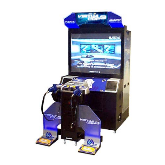
DELUXE TYPE
Manufactured in the UK by
REV 0
Advertisement
Table of Contents

Related Manuals for Sega Virtua Cop 3 Deluxe Type


Summary of Contents for Sega Virtua Cop 3 Deluxe Type
- Page 1 420-6759-01UK REV 0 SERVICE MANUAL DELUXE TYPE Before using this product, read this SERVICE MANUAL carefully to understand the contents stated herein. After reading this manual, be sure to keep it available nearby the product or somewhere convenient in order to be able to refer to it whenever necessary.
-
Page 2: Table Of Contents
CONTENTS BEFORE USING THIS PRODUCT......................1 1.1. INSPECTIONS IMMEDIATELY AFTER TRANSPORTING THE PRODUCT TO THE LOCATION ..2 INTRODUCTION TO THIS SERVICE MANUAL ...................4 INSTALLATION AND SERVICE INSTRUCTIONS................5 3.1. HANDLING AND INSTALLATION PRECAUTIONS ................5 3.2. COIN HANDLING..........................5 3.3. NAME OF PARTS ..........................6 3.4. - Page 3 5.2.2. SYSTEM INFORMATION ......................58 5.2.3. JVS TEST ..........................59 5.2.4. INPUT TEST Screen.........................60 5.2.5. SOUND TEST ...........................61 5.2.6. C.R.T. TEST ..........................62 5.2.7. COIN ASSIGNMENTS ......................63 5.2.8. CLOCK SETTING ........................66 5.2.9. NETWORK SETTING (CORE) ....................67 5.2.10. NETWORK SETTING (MEDIA) ....................68 5.3. GAME TEST MODE.........................69 5.3.1.
-
Page 4: Before Using This Product
Depending on the potential risk, terms such as” WARNING!” “CAUTION” and “IMPORTANT!” are used where an explanation is given that requires special attention. SEGA is not responsible for injury or damage caused by use in a manner contrary to the instructions given in this document. -
Page 5: Inspections Immediately After Transporting The Product To The Location
TO THE LOCATION · Only QUALIFIED SERVICE PERSONNEL should carry out inspection. Normally, at the time of shipment, SEGA products are in a state to allowing usage immediately after transporting to the location. Nevertheless, an irregular situation may arise during transportation preventing this. - Page 6 CONCERNING THE STICKER DISPLAY CONCERNING WARNING STICKERS SEGA product has stickers describing the product SEGA product has warning displays on manufacture number (Serial Number) and stickers, labels or printed instructions electrical specification. If you require service adhered/attached to or incorporated in the assistance you will require the Serial Number.
-
Page 7: Introduction To This Service Manual
INTRODUCTION TO THIS SERVICE MANUAL SEGA ENTERPRISES LTD. supported by its experience in electronic high technology of VLSI’s, microprocessors etc. and with a wealth of experience, has for more than 30 years been supplying various innovative and popular games to the world market. This Service Manual is intended to provide detailed descriptions together with all the necessary information covering the general operation of electronic assemblies, electro-mechanicals, servicing controls, spare parts, etc. -
Page 8: Installation And Service Instructions
Standard Sega machines are fitted with a SR3 coin mechanism, however, as a service to our customers Sega machines can be supplied with no coin mechanism or door allowing the customer to fit a coin handling option from the approved list. Fit only the coin handling arrangements detailed below and follow the instructions provided in section 3.8. -
Page 9: Name Of Parts
3.3. NAME OF PARTS Weight (kg) Width (cm) Length (cm) Height (cm) [Approx] BILLBOARD MAIN CABI DX GUN CABI When Assembled... -
Page 10: Accessories
3.4. ACCESSORIES The machine is supplied with an installation kit. Please ensure the following parts are supplied: Item Part No. Description Component Reference VCT-0520UK ASSY BILLBOARD DX HOD-0006 L BRKT 440-CS0186UK STICKER C EPILEPSY MULTI VCT-0502UK WIRE COVER R VCT-0501UK WIRE COVER L 000-T00412-0B M4X12 MSCR TH BLK... -
Page 11: Shipping The Game Board
3.5. SHIPPING THE GAME BOARD Replacement or repair of the Game Board (Chihiro) for this product should be undertaken at the appropriate repair centre. Be sure to follow the specifications below when requesting repairs/sending the board to the repair centre. Not following the specifications may result in the board not being accepted or in extra charges being made. -
Page 13: Shipping The Media Board
3.6. SHIPPING THE MEDIA BOARD When sending the Media Board for repairs, follow the specifications below and request repairs or send the Board to your retailer/the repair centre. Not following the specifications may result in the board not being accepted or in extra charges being made. -
Page 14: Shipping The Gd-Rom Drive
3.7. SHIPPING THE GD-ROM DRIVE · When returning the GD-ROM DRIVE for repair or replacement, be sure to package it in the original card transit box - THERE ARE NO USER- SERVICEABLE PARTS INSIDE. · Ensure the GD-ROM Disk is removed and the GD-ROM Drive Lid is replaced on the unit, with fixing screw, before packaging. -
Page 15: Assembly Instructions
3.8. ASSEMBLY INSTRUCTIONS · Perform the assembly by following the procedure herein stated. Failure to comply with the instructions, for example, inserting the plug into an outlet at a stage not mentioned in this manual can cause an electric shock ·... -
Page 16: Assemble The Machine
3.8.1. ASSEMBLE THE MACHINE 3.8.1.1.ASSEMBLE THE PTV 1. Place the PTV and PTV Cabinet in roughly their final position, in close enough proximity to make the connections shown. It is imperative that the earth eyes are connected to the plate at the bottom of the PTV. 2. -
Page 17: Fitting The Billboard
3.8.1.2.FITTING THE BILLBOARD 1. Have two people lift the Billboard and place it on top of the PTV. Place the Billboard so that the two Mask Bracket Uppers attached in Step 1 fit into the rectangular holes in the Billboard base plate, then slide the Billboard toward the PTV screen. - Page 18 TRUSS SCREW (x2) BLACK M4x8, FLAT WASHER BILLBOARD LID 3. Having removed the Billboard Lids from both sides, attach the base plate with 2 screws SCREW M5 x 16, W/FLAT & SPRING WASHERS 4. Pull the wires through the rectangular holes on either side of the Billboard and connect them to the connectors on the roof of the PTV.
- Page 19 5. Attach Wire Covers L (left) and R (right) to protect the connectors on the right and left sides of the roof of the PTV. The larger wire cover is Wire Cover L and should be attached to the 2 connectors. 6.
-
Page 20: Installing The Foot Pedal
3.8.1.3. INSTALLING THE FOOT PEDAL 1. Attach the pedal and fence to the left and right of the controller cabinet. The foot base and fence have right and left versions; make sure they are aligned correctly before attaching. - Page 21 Instructions for attaching the R (right) side are included in this manual. The procedure for attaching the L (left) side is the same. 2. Attach the foot base to the U-shaped bracket sticking out from the side of the controller cabinet by inserting it from the side.
- Page 22 7. Remove the 2 screws and remove the plate sash from the pedal. 8. Insert the fence into the pedal and attach with 4 hexagonal bolts. Use the large flat washers with the hexagonal bolts used on the cabinet.
- Page 23 9. Reattach the plate sash as it was before. 10. Securely tighten the 4 hexagonal bolts on the pedal. 11. Attach the base hole lid to the foot base and attach 6 screws.
-
Page 24: Attach The Gun Cabinet
3.8.1.4. ATTACH THE GUN CABINET 1. After fitting the guard rails to the gun cabinet fit the gun cabinet to the main cabinet. 2. Slide the gun cabinet into the hole in the main cabinet as shown. 3. Fix the gun cabinet in position using the joint brackets and M8 bolts provided. -
Page 25: Leg-Levelling Procedure
3.8.2. LEG-LEVELLING PROCEDURE · This operation requires 2 people. Ensure that all leg adjusters are in contact with the floor otherwise the machine may move and cause injury. · Only QUALIFIED SERVICE PERSONNEL should carry out this operation. This machine has 4 castors and 8 leg adjusters. When the installation position is decided, unscrew the leg adjusters so that they raise each castor a minimum of 5mm from the floor. -
Page 26: Coin Handling Installation
3.8.3. COIN HANDLING INSTALLATION. · Only QUALIFIED SERVICE PERSONNEL should carry out this operation. When fitting the coin mechanism to the door please refer to the specific manufacturers installation instructions for that coin mechanism. To fit the door to the machine, follow the procedure below. ·... -
Page 27: Wiring Connections
3.8.3.1.WIRING CONNECTIONS. COIN MECH LOOM INSTALLATION C220B LM1006IDC · Attach the lamp holder to the bracket on the coin return button. LM1006LAMP-0.1 · Attach one 15-way connector to the C220 coin mech. · Attach the other 15-way connector to Validator A on the credit board. -
Page 28: Connection To The Power Supply
3.8.4. CONNECTION TO THE POWER SUPPLY · This operation may only be carried out once the machine has been completely assembled. · Only QUALIFIED SERVICE PERSONNEL should carry out this operation. Once the machine has been fully assembled and fixed in position it is ready to be connected to the power supply 1. -
Page 29: Adjacent Control Interference Prevention
3.8.5. ADJACENT CONTROL INTERFERENCE PREVENTION · Be sure that the machine is not connected to the mains supply before attempting this operation. · Be careful not to damage wiring. · The Game Board area should be accessed only if necessary. ·... -
Page 30: Assembly Check
3.9. ASSEMBLY CHECK · Only QUALIFIED SERVICE PERSONNEL should carry out this operation. In the TEST MODE, ensure that the assembly has been made correctly and IC Board is satisfactory (refer to Section ). In the test mode, perform the following test: MEMORY TEST 3.9.1. -
Page 31: Test
3.9.2. C.R.T. TEST In the TEST mode menu, selecting C.R.T. TEST allows the screen (on which the moniter is tested) to be displayed. Although the moniter adjustments have been made at the time of shipment from the factory, make judgment as to whether an adjustment is needed by watching the test mode screen. -
Page 32: Input Test
3.9.3. INPUT TEST Selecting the INPUT TEST on the game test mode menu screen causes the screen (on which each switch is tested) to be displayed. Press each switch. If the display beside each switch indicates "ON," the switch and wiring connections are satisfactory. -
Page 33: Gun Adjustment
3.9.5. GUN ADJUSTMENT Before starting the operation, play the game by yourself and make sure that the gun readjustment is not needed and that you can play the game without a problem. Although completed at the factory, the gun adjustment may be necessary because, after the adjustment, the product has been disassembled for packing and shipping. -
Page 34: Moving The Machine
3.10. MOVING THE MACHINE · When moving the machine, be sure to remove the plug from the power supply. Moving the machine with the plug inserted can cause the power cord to be damaged, resulting in a fire or electric shock. ·... -
Page 35: Fuses
3.11. FUSES · Never touch places other than those specified. Touching places other than those specified can cause electric shock and short circuit. Disconnect the machine from the supply before attempting the replacement of any fuse. · Only QUALIFIED SERVICE PERSONNEL should replace FUSES. ·... -
Page 36: Replacement Of Fluorescent Lamp And Other Lamps
3.12. REPLACEMENT OF FLUORESCENT LAMP AND OTHER LAMPS · Never touch places other than those specified. Touching places other than those specified can cause electric shock and short circuit. Disconnect the machine from the supply before attempting the replacement of any lamp. ·... -
Page 37: Lamp Replacement
3.12.2.LAMP REPLACEMENT 1. Remove the control panel cover as shown by removing the 8 screws holding it in position. 2. Carefully lift the control panel cover up until it is possible to disconnect the wire harness plugs attaching the start switches to the cabinet. 3. -
Page 38: Troubleshooting
3.13. TROUBLESHOOTING · Only QUALIFIED SERVICE PERSONNEL should carry out these procedures. If a problem occurs, first check the wiring connections. PROBLEMS CAUSE COUNTERMEASURES When the main The power is not ON. Firmly insert the plug into the outlet. switch is turned ON, the machine is not activated Incorrect power source/voltage. -
Page 39: Controller Unit
3.14. CONTROLLER UNIT · Only QUALIFIED SERVICE PERSONNEL should carry out these procedures. · During daily cleaning and maintenance, check the surface of the control unit (Gun Controller) for cracks and other damage and ensure that screws are securely fastened. Loose screws, cracks, and other damage could cause harm to players and other customers if left un-repaired. -
Page 40: Control Unit (Gun Controller)
3.14.2.CONTROL UNIT (GUN CONTROLLER) · Follow these directions carefully to avoid damaging or losing small parts. In the cases where the gun's operation is not satisfactory or the gun sight deviates from the direction in which the control unit is pointed, the gun's interior parts may have been damaged. Replace the parts by disassembling the gun using the following procedure. - Page 41 Remove the trigger microswitch from the right shell. MICROSWITCH / 509-5080 Remove the soldering and detach the microswitch. Remove the Change Button from the right shell. Remove the spring from the right shell.
- Page 42 Remove 1 screw and detach the microswitch (with SW bracket attached) from the right shell. SCREW (1) / M3 x 8, W/flat & spring washers Disconnect the microswitch wire connector. 10. Remove the 2 screws and remove the SW bracket from the microswitch. SCREW (2) / M2 x 10, W/flat &...
- Page 43 Remove the soldering and extract the microswitch. Solder in the new microswitch and reassemble the Gun Controller. Be careful not to tighten the screws too tightly. Test the trigger (or Weapon Change Button) to make sure that the new microswitch functions properly.
-
Page 44: Replacing The Sensor Unit
3.14.2.2.REPLACING THE SENSOR UNIT Follow instructions (1) – (3) of “Replacing the Microswitch” to remove the left shell. Detach the connector and pull out the sensor unit. SENSOR UNIT / JPT-2030... -
Page 45: Gameboard
3.15. GAMEBOARD · Turn off the mains power and remove the power cord before opening the machine. · To prevent risk of shock or fire, be careful not to damage any wiring. · The GAME BOARD should not require any work to be carried out upon it. All settings and tests can be achieved without access to the GAME BOARD. - Page 46 5. Pull the ASSY MAIN BD out of the Cabinet and set it on a level surface before continuing. 6. Unplug all connectors connected to the Chihiro Board. 7. Unplug the GD Cable connector on the side of the Media Board on the Chihiro Board. 8.
-
Page 47: Removing The Gd-Rom Drive
3.15.2.REMOVING THE GD-ROM DRIVE Take out the ASSY MAIN BD from the PTV cabinet and remove the GD-ROM Drive from the ASSY MAIN BD as follows: Following the above procedure (steps 1 to 5), take out the ASSY MAIN BD. 2. -
Page 48: Composition Of The Game Board
3.16. COMPOSITION OF THE GAME BOARD... -
Page 49: Periodic Check And Inspection
3.17. PERIODIC CHECK AND INSPECTION The items listed below require periodic check and maintenance to retain the performance of the machine and ensure safe operation: · Be sure to check annually to see if the power cords are damaged. The plug is securely inserted and that there is no dust in the interior of the machine or between the socket and the power cord. -
Page 50: How To Play
HOW TO PLAY Use this section to confirm the machine is operating correctly; if the machine doesn’t operate as described there may be a fault. While power is connected, the billboard is continuously lit and demonstration footage and ranking data are displayed on the screen. -
Page 51: Game Contents
4.1. GAME CONTENTS Press the appropriate START button to begin play as 1P or 2P. If enough credits for a game are remaining, the other player’s START button will flash. Press the flashing START button to join a game. -
Page 52: The Main Characters
4.1.1. The Main Characters Virtua Cop 3 has two main characters, RAGE (1P) and SMARTY (2P). JANET appears as an allied character during the game but cannot be controlled. 4.1.1.1.1P Character: RAGE Strong as an ox and just as uncontrollable, this hothead tends to act before he thinks. -
Page 53: Game Screen
4.1.2.4.Game Screen 1. Points/Point Multiplier Meter The eight-digit number indicates total points earned. After 3-point shots, Justice shots, and other special attacks the name of the attack and points earned are shown beneath the score display. The more enemies you shoot, the more the gauge above the score display lengthens. When the gauge is completely filled, your level increases. -
Page 54: Es Gauge
4.1.2.5.ES Gauge Shows remaining energy in ES Mode. The ES Gauge falls during ES Mode and recovers when you defeat enemies. 4.1.2.5.1.ES Mode (Exceeding Sense Mode) Hold down the foot pedal to activate ES Mode. ES Mode enhances your character’s senses, making time appear to move slower. -
Page 55: Game Over
4.1.2.5.2.ES Attack (Exceeding Sense Attack) ES Attack begins automatically in certain scenes. ES Attack displays special targeting sights that show points of particular vulnerability for a limited time. Speed and accuracy are essential. Hit all the targeted areas within the time given to clear the ES Attack. -
Page 56: Maintenance Instructions
MAINTENANCE INSTRUCTIONS 5.1. EXPLANATION OF TEST AND DATA DISPLAY Perform the tests and data check periodically when installing the machine initially or collecting cash, or when the machine does not function correctly. Perform checks in accordance with the explanations given in this section. - Page 57 ITEM DESCRIPTION / REFERENCES INTERVAL INSTALLATION OF When the machine is installed perform the following Monthly THE MACHINE checks: · Check to see that each setting is as per the standard settings input at the time of shipment. 3.9 · In the INPUT TEST mode, check each switch. 3.9.3 ·...
-
Page 58: Vts Assembly
5.1.1. VTS ASSEMBLY · Do not touch places other than those specified. Touching places not specified could cause an electric shock or short circuit. Opening the Coin Chute door will reveal the VTS Assembly shown above. The function of each switch is as follows. -
Page 59: System Test Menu Mode
5.2. SYSTEM TEST MENU MODE System Test Mode can be used to check that the main circuit operations are correct, adjust Monitor colour, and perform coin/credit settings. However, this product can only be used with the settings shown below. SOUND TEST - OUTPUT TYPE: STEREO COIN ASSIGNMENTS - COIN CHUTE TYPE: COMMON... -
Page 60: Media Board Test
5.2.1. MEDIA BOARD TEST Powering off the system during the MEDIA BOARD TEST with a DIMM BOARD will erase the game programme data. It may be necessary to reload the data. Always wait for the test to complete before attempting to exit. MEDIA BOARD TEST is used to check the memory and IC on the MEDIA BOARD connected to the Chihiro. -
Page 61: System Information
5.2.2. SYSTEM INFORMATION Use SYSTEM INFORMATION to check version and other information for system programmes. Screens may differ depending on the type of MEDIA BOARD connected to the unit. The following is the SYSTEM INFORMATION screen for a unit with a DIMM BOARD. Press the TEST Button to return to the SYSTEM MENU screen. -
Page 62: Jvs Test
5.2.3. JVS TEST JVS TEST is used to verify the specs of the I/O BOARD connected to the Chihiro and to run input tests. I/O BOARD specs are displayed initially. Screens may differ depending on the type of I/O BOARD connected to the unit. Use the SERVICE Button to move the cursor to the desired test item. -
Page 63: Input Test Screen
5.2.4. INPUT TEST Screen On-screen values change according to the input from switches and the volume. SYSTEM, PLAYER Values change with input from control panel/other switches. COIN Increases with input from the COIN SWITCH. The count is cleared when exiting TEST MODE. ANALOG Displays analog values from "0000"... -
Page 64: Sound Test
5.2.5. SOUND TEST Use SOUND TEST to test sound output and to select the stereo/mono/surround setting. (1) Use the SERVICE Button to move the cursor to the desired test item. (2) Press the TEST Button to enter the selected item. (A) OUTPUT TYPE (STEREO, MONO, SURROUND) Select the sound output from the I/O PANEL audio output interface setting among STEREO, MONO and SURROUND. -
Page 65: Test
5.2.6. C.R.T. TEST Use the C.R.T. TEST to adjust monitor colours and verify screen size. COLOUR CHECK Screen (1) Monitor COLOUR CHECK screen is displayed initially. Each of the colours (red, green and blue) is darkest at the far left and gets progressively lighter (32 steps) towards the right. -
Page 66: Coin Assignments
5.2.7. COIN ASSIGNMENTS Use COIN ASSIGNMENTS to set the credit rate for each coin inserted. (1) Use the SERVICE Button to move the cursor to the desired test item. (2) Press the TEST Button to change the setting or to open the detailed settings. (3) Move the cursor to EXIT and press the TEST Button to return to the SYSTEM MENU screen. - Page 67 (C) COIN TO CREDIT RATE Set the CREDIT RATE for each coin inserted. The "r COIN(S) COUNT AS £ CREDIT(S)" setting indicates that "Inserting r coins equals £ credits". Set this to "FREE PLAY" to allow game play without credits. When (A) COIN CHUTE TYPE is set to "COMMON", COIN CHUTE #2 settings are restricted to some extent by the settings for COIN CHUTE #1.
- Page 68 (H) GAME COST SETTING Use this mode to set the number of credits required to start a game. Screens may differ depending on the game. Set the number of credits required to start a game. (J) Set the number of credits required to continue a game.
-
Page 69: Clock Setting
5.2.8. CLOCK SETTING Use the SERVICE Button to move the cursor to the item to be set. (1) Move the cursor to the desired item and press the TEST Button to increase values. (2) The max value for YEAR is "2099"; further increases return the value to "2000". (3) Move the cursor to EXIT and press the TEST Button to return to the SYSTEM MENU screen. -
Page 70: Network Setting (Core)
5.2.9. NETWORK SETTING (CORE) Use the LAN PORT attached to the Main Board, and carry out the settings necessary for network communication. *This game does not support network communication connections. * HIS OPTION IS FOR POSSIBLE FUTURE GAMES ONLY ELECT EXIT AND GO DIRECTLY TO THE NEXT TEST MODE Use the SERVICE Button to move the cursor to the desired test item. -
Page 71: Network Setting (Media)
5.2.10.NETWORK SETTING (MEDIA) Use NETWORK SETTING to establish and test network connections. This is only displayed when a network enabled MEDIA BOARD is connected to the Chihiro. *This game does not support network communication connections and only an error message will be displayed. * HIS OPTION IS FOR POSSIBLE FUTURE GAMES ONLY ELECT EXIT AND GO DIRECTLY TO THE NEXT TEST MODE... -
Page 72: Game Test Mode
5.3. GAME TEST MODE · When changing the game configuration, changes will not take effect until the Game Test Mode has been completed. Be sure to exit the Game Test Mode properly after configuration changes. · Do not configure the game in ways not described in this text. It is possible that the game will not function properly. -
Page 73: Input Test
5.3.1. INPUT TEST Select INPUT TEST to display the following screen and check the status of input devices. This test should be used periodically to check that each input device is functioning correctly. The items refer to the following input devices. ●... -
Page 74: Output Test
5.3.2. OUTPUT TEST Select OUTPUT TEST to display the following screen and check the status of each lamp. This test should be used periodically to check that the lamps are functioning correctly. Press the SERVICE Button to move the cursor and the TEST Button to select. Displays ON when selected. Actual screen may differ for depending on cabinet type. -
Page 75: Game Assignments
5.3.3. GAME ASSIGNMENTS Select GAME ASSIGNMENTS to display the current game settings and make changes. Perform the following settings for each item. ● DIFFICULTY: Set the game’s difficulty level. Five settings are available, from VERY EASY to VERY HARD. ● LIFE: Set the number of lives each player starts the game with. -
Page 76: Gun Adjustment
5.3.4. GUN ADJUSTMENT Select GUN ADJUSTMENT to display the following screen. This screen allows you to adjust the gun using the five calibration targets (TOP, LEFT, CENTER, RIGHT, BOTTOM). Use each target to calibrate as follows. Use the standard gun controller, carefully aim at the correct target and pull the trigger to calibrate the value. Select between the calibration targets with the 1P and 2P START buttons or SERVICE button. -
Page 77: Bookkeeping
for 1P, red for 2P) where the controller hits the screen. Use this cursor to check calibration. ● OUT OF SCREEN: Displays “OUT OF SCREEN” when the controller is pointed outside the screen. Values cannot be set when the controller is out of screen. Changes to settings are not enabled until the Test Mode is exited. - Page 78 Press the TEST Button to display the next screen. The display items for the screen (Page 2 of 3) are as follows. ● NUMBER OF GAMES: The total number of games played by 1P and 2P. ● NUMBER OF GAME STARTS: Number of games started.
-
Page 79: Backup Data Clear
PLAY TIME HISTOGRAM shows the number of plays and the respective play times. This histogram should be referred to when setting the Game Difficulty. This displays play times on a scale from 0M00S to 9M59S with 30-second intervals. All play times over ten minutes are included in the item OVER 10M00S. Press the TEST Button after viewing. -
Page 80: Coin Mech Installation And Credit Board Set Up
COIN MECH INSTALLATION AND CREDIT BOARD SET UP 6.1. INTRODUCTION Game credits between the Coin Mechanism and the game board for this machine are controlled by a VTS board. This electronic circuit allows the price of play to be set for a range of different countries. These functions are set on Dual In Line (DIL) PCB mounted switches. - Page 81 Credit Board Mode Settings Switch 3 Country Setting Switch 3 Setting Coin Validator Programming C120/SR3 Only SW1 SW2 SW3 SW4 SW5 SW6 COIN1 COIN2 COIN3 COIN4 COIN5 COIN6 COIN7 COIN8 COIN9 COIN10 COIN11 COIN12 Coin Controls OFF OFF £1 50p new 50p old C220 Parallel Coin Controls...
-
Page 82: Price Of Play Settings Uk
6.1.1. PRICE OF PLAY SETTINGS UK Price Bonus DIL Switch 1 Switch 1 Switch 2 Switch 3 Switch 4 Switch 5 No Bonus 6 = 50p No Bonus 3 = 50p 6 = £1 12 =£2 No Bonus 1.66 = 50p 4 = £1 8 = £2 2 = 50p... -
Page 83: Price Of Play Settings Euro
6.1.2. PRICE OF PLAY SETTINGS EURO Price Bonus DIL Switch 1 Switch 1 Switch 2 Switch 3 Switch 4 Switch 5 10¢ No Bonus 10¢ 6 = 50¢ 20¢ No Bonus 20¢ 3 = 50¢ 6 = €1 12 =€2 30¢... -
Page 84: Price Of Play Settings Austria-Czech-Denmark-Norway-Israel-France2
6.1.3. PRICE OF PLAY SETTINGS Austria-Czech-Denmark-Norway-Israel- France2 Price Bonus Switch 1 Switch 1 Switch 2 Switch 3 Switch 4 Switch 5 No Bonus 11 = 10 6 = 5 No Bonus 6 = 10 3 = 5 No Bonus 4 = 10 2 = 5 No Bonus 3 = 10... -
Page 85: Design Related Parts
DESIGN RELATED PARTS Item Part No. Description VCT-0525UK BILLBOARD PLATE VCT VCT-0531UK STICKER BILLBOARD VCT VCT-0526 BILLBOARD PLATE L VCT VCT-0527 BILLBOARD PLATE R VCT VCT-1008UK STICKER CABI TOP L VCT-1009UK STICKER CABI TOP R VCT-1061UK STICKER LID UPPER VCT-2001-BUK BUTTON SHEET VCT DX VCT-2001-C-01UK STICKER CTRL PNL TOP VCT... -
Page 86: Parts List
PARTS LIST 8.1. VCT-0000UK - TOP ASSY VIRTUA COP 3 DX Item Component Part Description Component Reference VCT-0500UK ASSY PTV VCT-1000UK ASSY PTV CABI DX VCT-1100UK ASSY CONTROLLER CABINET HOD-2003 DENOMI PLATE SGM-4346 POLY COVER 1200X1200X1300 SGM-4426 POLY COVER 800X750X900 421-7987-VCT-D STICKER ELEC SPEC VCT DX NEXT TO AC UNIT... -
Page 87: Vct-0500Uk - Assy Ptv
8.2. VCT-0500UK - ASSY PTV Item Component Part Qty. Description Component Reference SPX-0530UK ASSY MASK VCT-0511UK STICKER PTV SIDE HOD-1101 PTV HOLDER SPX-0532UK PROTECT SCREEN PTV (101)-1 SPX-0533UK RETAINING BRKT HORIZ PTV (5)-2 200-5788-31 PROJECTION DSPL T 50TYPE 31K 000-T00520-0B M5X20 MSCR TH BLK (1)-4 000-T00525-0B... -
Page 88: Vct-0520Uk - Assy Billboard Dx
8.3. VCT-0520UK - ASSY BILLBOARD DX... - Page 89 Item Component Part Description Component Reference VCT-0521UK BILLBOARD BOX VCT-0522UK BILLBOARD SASH VCT-0523UK BILLBOARD LID VCT-0524UK BD BASE VCT-0525UK BILLBOARD PLATE VCT VCT-0526 BILLBOARD PLATE L VCT KD PART VCT-0527 BILLBOARD PLATE R VCT KD PART VCT-0528UK PLATE HOLDER L VCT-0529UK PLATE HOLDER R VCT-0530...
-
Page 90: Spx-0530Uk Assy Mask
8.4. SPX-0530UK ASSY MASK ITEM PART NUMBER DESCRIPTION COMPONENT REF HOD-1151 MASK BASE JPT-1082 IR COVER 101 838-13145-02 LED BD GUN SENSE HOD (101)-20 201 050-U00300 M3 NUT NYLOK PAS (101)-20 202 068-330808-PN M3 WSHR 8OD FLT NYLON EARTH-1 203 050-F00400 M4 NUT FLG SER PAS 301 SPY-60024 WIRE HARN MASK SHORT... -
Page 91: Vct-1000Uk Assy Ptv Cabi Dx
8.5. VCT-1000UK ASSY PTV CABI DX... - Page 92 Item Component Part Description Component Reference VCT-1002UK PTV CABINET HOD-1020UK ASSY AC UNIT UK VCT-1060UK ASSY LID UPPER VCT-1070UK ASSY LID LOWER VCT-4000UK ASSY MAIN BD DX HOD-1070UK ASSY SPEAKER UK SPX-1010UK SPEAKER COVER HOD-1003 LOCKING BRKT HOD VCT-1530UK FAN UNIT DC UK 253-5460-01 AIR VENT BLACK 253-5396-91...
-
Page 93: Hod-1020Uk Assy Ac Unit
8.6. HOD-1020UK ASSY AC UNIT INDENT PART NO. DESCRIPTION COMPONENT REF HOD-1021UK AC BRKT UK LB1096 STICKER PROTECTIVE EARTH (EARTH STUD) EP1379 FILTER EMI 10A ARCOTRONICS SW1109 SWITCH ROCKER 250V AC EP1302 EUROSOCKET FUSED 1OA 250Vac 514-5078-5000 FUSE 5X20 CERAMIC SB 5000mA 310-5029-D508 HEAT SHRINK SLEEVING 50.8DIA 0.04... -
Page 94: Vct-1060Uk Assy Lid Upper
8.7. VCT-1060UK ASSY LID UPPER Item Component Part Qty. Description Component Reference HOD-1051-A FRONT LID U BLANK VCT-1061UK STICKER LID UPPER TH1015UK LOCKING TONGUE UK 220-5575UK LOCK... -
Page 95: Vct-1070Uk Assy Lid Lower
8.8. VCT-1070UK ASSY LID LOWER Item Component Part Qty. Description Component Reference HOD-1061-AUK FRONT LID L BLANK HOD-1062-A FRONT LID BRKT BLANK 050-F00400 M4 NUT FLG SER PAS (2)-3 060-F00400-0B M4 WSHR FORM A FLT BLK (2)-3... -
Page 96: Hod-1070Uk Assy Speaker
8.9. HOD-1070UK ASSY SPEAKER ITEM PART NO. DESCRIPTION COMPONENT REF CPT-1061UK SPEAKER BRKT UK 130-5096 ASSY SERVO SPEAKER BOX 000-P00512-W M5X12 MSCR POSI PAN W/FS PAS (101)-2 HOD-60025 WIRE HARN SPEAKER UNIT... -
Page 97: Vct-1100Uk Assy Controller Cabinet
8.10. VCT-1100UK ASSY CONTROLLER CABINET Item Component Part Description Component Reference VCT-2000UK ASSY CTRL PANEL DX VCT-1103 HOLDER VTS-HOD-D VTS BOARD HOD VCT-1302UK GUN HOLDER CABI 253-5366 CASH BOX JPT-3101 TUBE CLAMP HOD-1304 JOINT PART LID DUT-0302UK COIN PATH PLATE SPY-1106 HOLDER BRKT HOD-1307-A... - Page 98 CONTINUED FROM PREVIOUS PAGE ITEM PART NUMBER DESCRIPTION COMPONENT REFERENCE 000-T00416-0B M4X16 MSCR TH BLK (1)-8,(7)-4 068-441616-0B M4 WSHR 16OD FLT BLK (1)-8 008-T00430-0B M4X30 TMP PRF TH BLK (12)-8 000-T00440-0B M4X40 MSCR TH BLK (14)-4 000-P00420-W M4X20 MSCR PAN W/FS PAS (3)-4,(18)-5 030-000630-SB M6X30 BLT W/S BLK...
-
Page 99: Vct-1150Uk Assy Fence L
8.11. VCT-1150UK ASSY FENCE L Item Component Part Description Component Reference VCT-1151UK FENCE FRAME L VCT-1152 DESIGN PLATE L VCT-1153 GUARD PLATE L FAS-290034 M5 X15 HEX SKT LH CAP SCR STN (3)-6... -
Page 100: Vct-1160Uk Assy Fence R
8.12. VCT-1160UK ASSY FENCE R Component Item Component Part Description Reference VCT-1161UK FENCE FRAME R VCT-1162 DESIGN PLATE R VCT-1163 GUARD PLATE R FAS-290034 M5 X15 HEX SKT LH CAP SCR STN (3)-6... -
Page 101: Vct-1200 Assy Foot Pedal Dx
8.13. VCT-1200 ASSY FOOT PEDAL DX Item Component Part Description Component Reference VCT-1201 PEDAL BASE DX VCT-1202 PEDAL VCT-1203 FOOT PLATE artwork VCT-1204 COM SPRING VCT-1205 SPRING COVER VCT-1206 SHADE PLATE VCT-1207 SENSOR BRKT VCT-1208 WIRE COVER VCT-1209 STOPPER RUBBER VCT-1210 RUBBER CUSHION VCT-1211... -
Page 102: Vct-1300Uk Assy Foot Base L
8.14. VCT-1300UK ASSY FOOT BASE L Item Component Part Description Component Reference VCT-1301 FOOT BASE FRAME L 601-5699X LEG ADJUSTER BOLT M16 X 75 280-5009-01 CORD CLAMP 21 050-H01600-0B HEX NUT BLK M16 068-651616-0B M6 WSHR 16OD FLT BLK NOT SHOWN 030-000616-SB M6X16 BLT W/S BLK NOT SHOWN... -
Page 103: Vct-1310Uk Assy Foot Base R
8.15. VCT-1310UK ASSY FOOT BASE R Item Component Part Description Component Reference VCT-1311 FOOT BASE FRAME R 601-5699X LEG ADJUSTER BOLT M16 X 75 280-5009-01 CORD CLAMP 21 050-H01600-0B HEX NUT BLK M16 068-651616-0B M6 WSHR 16OD FLT BLK NOT SHOWN 030-000616-SB M6X16 BLT W/S BLK NOT SHOWN... -
Page 104: Hdt-1530Uk Assy Fan Unit Dc Uk
8.16. HDT-1530UK ASSY FAN UNIT DC UK Item Component Part Qty. Description Component Reference 105-5340-01 FAN BRKT LONG EC814500 12V DC FAN 120MM KD1 FN1012 MESH GUARD METAL 120mm FAN 000-P00312-W M3X12 MSCR PAN W/FS PAS (1)-4 HDT-60004UK WH 12V FAN LINK... -
Page 105: Vct-2000Uk Assy Ctrl Panel Dx
8.17. VCT-2000UK ASSY CTRL PANEL DX Item Component Part Qty. Description Component Reference VCT-2001-A-W CTRL PNL BLANK W/NUT PLATES VCT-2001-B BUTTON SHEET DX VCT-2001-C-01UK STICKER CTRL PNL TOP ENG VCT-2001-DUK STICKER CNTRL PANEL L VCT DX VCT-2001-EUK STICKER CNTRL PANEL R VCT DX 101 509-5712-01S SW PB W/L 6V YELLOW 301 HOD-60020... -
Page 106: Sensor Unit (Jpt-2030)
8.18. SENSOR UNIT (JPT-2030) ITEM NO. PART NO. DESCRIPTION NOTE JPT-2031 SENSOR HOLDER 838-13144 SENSOR BD GUN SENSE 012-P00306 TAP SCR #2 PH 3X6... -
Page 107: Vct-2100-01 Control Unit Exp
8.19. VCT-2100-01 CONTROL UNIT EXP Item Component Part Description Component Reference VCT-2101-01 COVER L EXP VCT-2102-01 COVER R EXP VCT-2103-01 HAMMER EXP VCT-2104 TRIGGER VCT-2105 CHANGE BUTTON VCT-2106 SW BRKT VCT-2107 COM SPRING JPT-2030 SENSOR UNIT 125-5124 TORSION SPRING 280-5124-04 NYLON CLAMP NK04 310-5029-D20 SUMITUBE F D 20MM... -
Page 108: Vct-4000Uk Assy Main Bd Dx
8.20. VCT-4000UK ASSY MAIN BD DX Item Component Part Description Component Reference SPY-4001UK WOODEN BASE MAIN BD DX TMB-4003 SW REGU BRKT 843-0001D-12 ASSY CASE BOX COM NAO DIMM EXP 105-5435 GD DRIVE BRKT STD LB1101 LABEL WARNING BATTERY 610-0617 GD-ROM DRIVE UNIT NAOMI 610-0652-0003 GD SOFT VCT... - Page 109 Continued from previous page Item Component Part Description Component Reference 012-P03512-F N6X1/2" S/TAP FLG PAS (103)-4 012-P00410-F N8X3/8" S/TAP FLG PAS (6)-4 SPY-60010UK WIRE HARN HIGH FRQNCY JUMPER CN1 ON IC BD GUN SENSE SPY 600-7159-039 WIRE HARN JVS PWR 039CM SPY-60009 WIRE HARN CTRL BD RECIEVER SMB-60013...
-
Page 110: Vct-4200Uk Assy Pwr Sply
8.21. VCT-4200UK ASSY PWR SPLY Item Component Part Qty. Description Component Reference HOD-4101UK WOODEN BASE PWR SPLY 560-5422UK XFMR NOB 838-11856CE-02 CONN BD W/FUSE 6.3A CE 000-P00416-W M4X16 MSCR PAN W/FS PAS (XFMR)-4 012-P00325 N4X1" S/TAP PAN PAS (CONN BD)-2 HDT-62000UK WIRE HARN AC-CONN BD HDT-62001UK... -
Page 111: Vct-Inst-Dx Assy Inst Kit Hdt Dx
8.22. VCT-INST-DX ASSY INST KIT HDT DX ITEM PART NO. DESCRIPTION COMPONENT REFERENCE VCT-0520UK ASSY BILLBOARD DX HOD-0006 L BRKT 440-CS0186UK STICKER C EPILEPSY MULTI VCT-0502UK WIRE COVER R VCT-0501UK WIRE COVER L 211 000-T00412-0B M4X12 MSCR TH BLK (18)-2, (19)-3 212 068-441616-0B M4 WSHR 160D FLT BLK (18)-2, (19)-3... -
Page 112: Appendix A - Electrical Schematic
APPENDIX A - ELECTRICAL SCHEMATIC 9.1. WIRE COLOURS THE WIRE COLOUR CODE IS AS FOLLOWS: PINK SKY BLUE BROWN PURPLE LIGHT GREEN Wires other than those of any of the colours listed above will be displayed by 2 alphanumeric characters: BLUE YELLOW GREEN... - Page 113 LOCATE A3 SCHEMATIC DRAWING 1 HERE...
- Page 114 LOCATE A3 SCHEMATIC DRAWING 2 HERE...
- Page 115 SEGA AMUSEMENTS EUROPE LTD./ SEGA SERVICE CENTRE Suite 3a Oaks House 12 - 22 West Street Epsom Surrey United Kingdom KT18 7RG Telephone: +44 (0) 1372 731820 Fax: +44 (0) 1372 731849 ã SEGA 2002...
Need help?
Do you have a question about the Virtua Cop 3 Deluxe Type and is the answer not in the manual?
Questions and answers