Table of Contents
Advertisement
420-6759-02UK
REV 0
SERVICE MANUAL
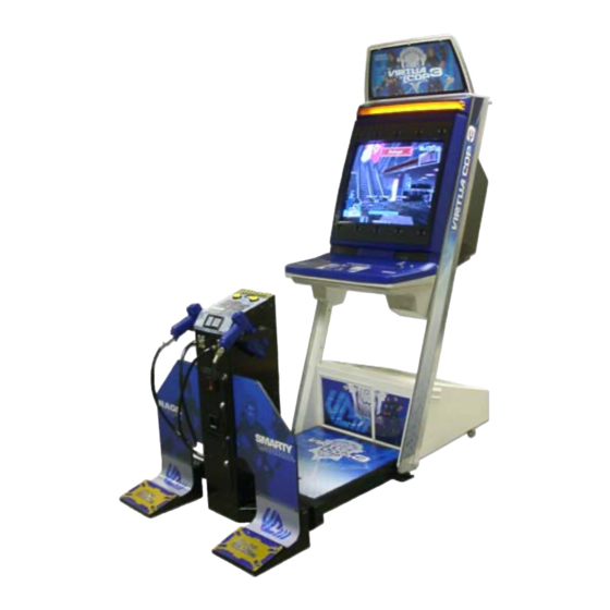
UPRIGHT TYPE
Before using this product, read this SERVICE MANUAL carefully to understand the contents stated herein.
After reading this manual, be sure to keep it available nearby the product or somewhere convenient in order to
be able to refer to it whenever necessary.
Manufactured in the UK by
Advertisement
Table of Contents

Related Manuals for Sega Virtua Cop 3


Summary of Contents for Sega Virtua Cop 3
- Page 1 420-6759-02UK REV 0 SERVICE MANUAL UPRIGHT TYPE Before using this product, read this SERVICE MANUAL carefully to understand the contents stated herein. After reading this manual, be sure to keep it available nearby the product or somewhere convenient in order to be able to refer to it whenever necessary.
-
Page 2: Table Of Contents
GAME CONTENTS ..........................50 5.1.1. The Main Characters ........................51 5.1.1.1. 1P Character: RAGE ......................51 5.1.1.2. 2P Character: SMARTY.....................51 5.1.2. Playing Virtua Cop 3........................51 5.1.2.1. Start a New Game ......................51 5.1.2.2. Calibrating at the Start of the Game ..................51 5.1.2.3. Mission Select........................51 5.1.2.4. - Page 3 6.3.3. MEDIA BOARD TEST.......................59 6.3.4. SYSTEM INFORMATION ......................60 6.3.5. JVS TEST ..........................61 6.3.6. INPUT TEST Screen.........................62 6.3.7. SOUND TEST ...........................63 6.3.8. C.R.T. TEST ..........................64 6.3.9. COIN ASSIGNMENTS ......................65 6.3.10. CLOCK SETTING .........................67 6.3.11. NETWORK SETTING (CORE) .....................68 6.3.12. NETWORK SETTING (MEDIA) ....................69 6.4.
-
Page 4: Before Using This Product
Depending on the potential risk, terms such as” WARNING!” “CAUTION” and “IMPORTANT!” are used where an explanation is given that requires special attention. SEGA is not responsible for injury or damage caused by use in a manner contrary to the instructions given in this document. -
Page 5: Inspections Immediately After Transporting The Product To The Location
TO THE LOCATION · Only QUALIFIED SERVICE PERSONNEL should carry out inspection. Normally, at the time of shipment, SEGA products are in a state to allowing usage immediately after transporting to the location. Nevertheless, an irregular situation may arise during transportation preventing this. - Page 6 CONCERNING THE STICKER DISPLAY CONCERNING WARNING STICKERS SEGA product has stickers describing the product SEGA product has warning displays on manufacture number (Serial Number) and stickers, labels or printed instructions electrical specification. If you require service adhered/attached to or incorporated in the assistance you will require the Serial Number.
-
Page 7: Introduction To This Service Manual
INTRODUCTION TO THIS SERVICE MANUAL SEGA ENTERPRISES LTD., supported by its experience in electronic high technology of VLSI’s, microprocessors etc. and with a wealth of experience, have for more than 30 years been supplying various innovative and popular games to the world market. This Service Manual is intended to provide detailed descriptions together with all the necessary information covering the general operation of electronic assemblies, electro-mechanicals, servicing controls, spare parts, etc. -
Page 8: Installation And Maintenance Instructions
Standard Sega machines are fitted with a SR3 coin mechanism, however, as a service to our customers Sega machines can be supplied with no coin mechanism or door allowing the customer to fit a coin handling option from the approved list. Fit only the coin handling arrangements detailed below and follow the instructions provided in section 4. -
Page 9: Name Of Parts
3.3. NAME OF PARTS Width (cm) Length (cm) Height (cm) CABINET FLOOR WHEN ASSEMBLED 93.5... -
Page 10: Accessories
3.4. ACCESSORIES HDT-INST-U ASSY INST KIT U/R Item Component Part Qty. Description Component Reference VCT-5000UK ASSY FLOOR VCT U/R VCT-INST-SUB1-U ASSY SUB1 INST VCT-INST-SUB2-U ASSY SUB2 INST PK0323 INST KIT PACKING WEDGE VCT-INST-SUB1-U ASSY SUB1 INST ITEM PART NO. DESCRIPTION COMPONENT REF. -
Page 11: Shipping The Game Board
3.5. SHIPPING THE GAME BOARD Replacement or repair of the Game Board (Chihiro) for this product should be undertaken at the appropriate repair centre. Be sure to follow the specifications below when requesting repairs/sending the board to the repair centre. Not following the specifications may result in the board not being accepted or in extra charges being made. -
Page 13: Shipping The Media Board
3.6. SHIPPING THE MEDIA BOARD When sending the Media Board for repairs, follow the specifications below and request repairs or send the Board to your retailer/the repair centre. Not following the specifications may result in the board not being accepted or in extra charges being made. -
Page 14: Shipping The Gd-Rom Drive
3.7. SHIPPING THE GD-ROM DRIVE · When returning the GD-ROM DRIVE for repair or replacement, be sure to package it in the original card transit box - THERE ARE NO USER- SERVICEABLE PARTS INSIDE. · Ensure the GD-ROM Disk is removed and the GD-ROM Drive Lid is replaced on the unit, with fixing screw, before packaging. -
Page 15: Assembly Instructions
3.8. ASSEMBLY INSTRUCTIONS · Perform the assembly by following the procedure herein stated. Failure to comply with the instructions, for example, inserting the plug into an outlet at a stage not mentioned in this manual can cause an electric shock ·... -
Page 16: Installing The Display Card
3.8.1. INSTALLING THE DISPLAY CARD · Only QUALIFIED SERVICE PERSONNEL should carry out this operation. Insert ASSY BILLBOARD to the top part of the cabinet Secure with the two Tamperproof screws. -
Page 17: Installing The Floor
3.8.2. INSTALLING THE FLOOR · Ensure all connections are secure - poor connections can cause electric shock or short circuit. · Take care not to damage wiring during installation, as this can cause electric shock or short circuit. · Please read these instructions carefully and follow them in step by step. ·... - Page 18 Secure the Coin Tower to the Floor using the 6x M8 Hex head bolts and M8 washers (provided) at location shown in fig 5. Move the Coin Tower and Floor Assembly onto its side (Fig 6) and thread the Flexihose through the ribs on the underside of the Floor.
- Page 19 Refit the Elbow joint onto the open end of the Flexipipe. 10. Fit the Joint Bracket onto the machine end of the Floor (Fig 8) 11. Offer the Floor to the machine and fit the Flexipipe Elbow Joint into the recess as shown in Fig 9.
- Page 20 Push the Floor uptight to the machine and secure it using the 2 x M8 Chrome Shoulder Bolts provided (Fig 10 & 11). Finally, secure Joint Brkt L and Joint Brkt R to the Floor and Adjustable feet using 2 x M8 Hex HD Bolts Blk and 2 x M8 Washers Blk (Fig 12).
-
Page 21: Securing In Place (Leg Adjuster Adjustment)
3.8.3. SECURING IN PLACE (LEG ADJUSTER ADJUSTMENT) · Make sure all of the leg adjusters are in contact with the floor. If not the machine may move and cause injury. This operation requires 2 people. · Only QUALIFIED SERVICE PERSONNEL should carry out this operation. This machine has four castors and two leg adjusters. -
Page 22: Installing The Foot Pedal
3.8.4. INSTALLING THE FOOT PEDAL 1. Attach the pedal and fence to the left and right of the controller cabinet. The foot base and fence have right and left versions; make sure they are aligned correctly before attaching. - Page 23 Instructions for attaching the L (left) side are included in this manual. The procedure for attaching the R (right) side is the same. 2. Attach the foot base to the U-shaped bracket sticking out from the side of the controller cabinet by inserting it from the side.
- Page 24 5. Attach the pedal to the foot base using 4 hexagonal bolts. Be sure not to tighten the hexagonal bolts completely. 6. Pull wire from the pedal to the foot base and connect the connector on the end of the wire to the connector on the U-shaped bracket.
- Page 25 8. Insert the fence into the pedal and attach with 4 hexagonal bolts. Use the large flat washers with the hexagonal bolts used on the cabinet. (M8 x 20, W/SPRING WASHER, FLAT WASHER). 9. Reattach the plate sash as it was before. 10.
- Page 26 Ensure adequate ventilation is maintained as detailed below: (Actual machines may differ slightly from the illustration)
-
Page 27: Coin Handling Installation
3.8.5. COIN HANDLING INSTALLATION · Only QUALIFIED SERVICE PERSONNEL should carry out this operation. When fitting the coin mechanism to the door please refer to the specific manufacturers installation instructions for that coin mechanism. To fit the door to the machine, follow the procedure below. ·... -
Page 28: Wiring Connections
3.8.5.1. WIRING CONNECTIONS. COIN MECH LOOM INSTALLATION C220B LM1006IDC · Attach the lamp holder to the bracket on the coin return button. LM1006LAMP-0.1 · Attach one 15-way connector to the C220 coin mech. · Attach the other 15-way connector to Validator A on the credit board. -
Page 29: Connection To The Power Supply
3.8.6. CONNECTION TO THE POWER SUPPLY · Be sure that the machine is not connected to the mains supply before attempting this operation · Only QUALIFIED SERVICE PERSONNEL should carry out this operation. 1. The AC Unit is located on the right hand side of the base unit, when viewing the screen. It houses the IEC inlet, mains switch and fuse. -
Page 30: Adjacent Control Interference Prevention
3.8.7. ADJACENT CONTROL INTERFERENCE PREVENTION · Be sure that the machine is not connected to the mains supply before attempting this operation. · Be careful not to damage wiring. · The Game Board area should be accessed only if necessary. ·... -
Page 31: Assembly Check
3.9. ASSEMBLY CHECK · Only QUALIFIED SERVICE PERSONNEL should carry out this operation. In the TEST MODE, ensure that the assembly has been made correctly and IC Board is satisfactory (refer to Section ). In the test mode, perform the following test: 3.9.1. -
Page 32: Test
3.9.2. C.R.T. TEST In the TEST mode menu, selecting C.R.T. TEST allows the screen (on which the moniter is tested) to be displayed. Although the moniter adjustments have been made at the time of shipment from the factory, make judgment as to whether an adjustment is needed by watching the test mode screen. -
Page 33: Input Test
3.9.3. INPUT TEST Selecting the INPUT TEST on the game test mode menu screen causes the screen (on which each switch is tested) to be displayed. Press each switch. If the display beside each switch indicates "ON," the switch and wiring connections are satisfactory. -
Page 34: Gun Adjustment
3.9.5. GUN ADJUSTMENT Before starting the operation, play the game by yourself and make sure that the gun readjustment is not needed and that you can play the game without a problem. Although completed at the factory, the gun adjustment may be necessary because after the adjustment the product has been disassembled for packing and shipping. -
Page 35: Moving The Machine
3.10. MOVING THE MACHINE · When moving the machine, be sure to remove the plug from the power supply. Moving the machine with the plug inserted can cause the power cord to be damaged, resulting in a fire or electric shock. ·... - Page 36 (Actual machine may differ slightly from illustration)
-
Page 37: Controller
3.11. CONTROLLER · Follow these directions carefully to avoid damaging or losing small parts. In the cases where the gun's operation is not satisfactory or the gun sight deviates from the direction in which the control unit is pointed, the gun's interior parts may have been damaged. Replace the parts by disassembling the gun using the following procedure. - Page 38 Remove the trigger microswitch from the right shell. MICROSWITCH / 509-5080 Remove the soldering and detach the microswitch. Remove the Change Button from the right shell. Remove the spring from the right shell.
- Page 39 Remove 1 screw and detach the microswitch (with SW bracket attached) from the right shell. SCREW (1) / M3 x 8, W/flat & spring washers Disconnect the microswitch wire connector. 10. Remove the 2 screws and remove the SW bracket from the microswitch. SCREW (2) / M2 x 10, W/flat &...
- Page 40 Remove the soldering and extract the microswitch. Solder in the new microswitch and reassemble the Gun Controller. Be careful not to tighten the screws too tightly. Test the trigger (or Weapon Change Button) to make sure that the new microswitch functions properly.
-
Page 41: Replacing The Sensor Unit
3.11.1.2. REPLACING THE SENSOR UNIT Follow instructions (1) – (3) of “Replacing the Microswitch” to remove the left shell. Detach the connector and pull out the sensor unit. SENSOR UNIT / JPT-2030... -
Page 42: Replacement Of Led Board
3.12. REPLACEMENT OF LED BOARD · Only QUALIFIED SERVICE PERSONNEL should carry out these procedures. The operation of the ten LED boards located around the CRT can easily be checked by viewing from the front with the power switched on. Two red points of light from the LEDs should be visible through each of the ten black lenses: if any of the LEDs are not lit, the corresponding LED board(s) should be replaced as follows. -
Page 43: Replacement Of Fluorescent Lamp And Start Lamps
3.13. REPLACEMENT OF FLUORESCENT LAMP AND START LAMPS · Never touch places other than those specified. Touching places other than those specified can cause electric shock and short circuit. Disconnect the machine from the supply before attempting the replacement of any lamp. ·... -
Page 44: Start Lamp Replacement
3.13.2. START LAMP REPLACEMENT 1. Remove the control panel cover as shown by removing the 5 screws holding it in position. 2. Carefully lift the control panel cover up until it is possible to disconnect the wire harness plugs attaching the start switches to the cabinet. 3. -
Page 45: Game Board
3.14. GAME BOARD · Turn off the mains power and remove the power cord before opening the machine. · To prevent risk of shock or fire, be careful not to damage any wiring. · The GAME BOARD should not require any work to be carried out upon it. All settings and tests can be achieved without access to the GAME BOARD. - Page 46 5. Remove all connectors from the filter board of the Game Board. Also remove the GD cable connector from the DIMM Board. 6. Remove four screws securing the Game Board to the base. 7. Reassemble in reverse order.
-
Page 47: Removing The Gd-Rom Drive
3.14.2. REMOVING THE GD-ROM DRIVE Take out the ASSY MAIN BD from the cabinet and remove the GD-ROM Drive from the ASSY MAIN BD as follows: 1. Following the above procedure (steps 1 to 5), take out the ASSY MAIN BD. 2. -
Page 48: Composition Of The Game Board
3.15. COMPOSITION OF THE GAME BOARD... -
Page 49: Troubleshooting
3.16. TROUBLESHOOTING · Only QUALIFIED SERVICE PERSONNEL should carry out these procedures. If a problem occurs, first check the wiring connections. PROBLEMS CAUSE COUNTERMEASURES When the main switch The power is not ON. Firmly insert the plug into the outlet. is turned ON, the machine is not activated... -
Page 50: Fuses
3.17. FUSES · Never touch places other than those specified. Touching places other than those specified can cause electric shock and short circuit. Disconnect the machine from the supply before attempting the replacement of any fuse. · Only QUALIFIED SERVICE PERSONNEL should replace FUSES. ·... -
Page 51: Periodic Check And Inspection
PERIODIC CHECK AND INSPECTION The items listed below require periodic check and maintenance to retain the performance of the machine and ensure safe operation: · Be sure to check annually to see if the power cords are damaged, the plug is securely inserted and that there is no dust in the interior of the machine or between the socket and the power cord. -
Page 52: How To Play
HOW TO PLAY Use this section to confirm the machine is operating correctly; if the machine doesn’t operate as described there may be a fault. While power is connected, the billboard is continuously lit and demonstration footage and ranking data are displayed on the screen. -
Page 53: Game Contents
5.1. GAME CONTENTS Press the appropriate START button to begin play as 1P or 2P. If enough credits for a game are remaining, the other player’s START button will flash. Press the flashing START button to join a game. -
Page 54: The Main Characters
5.1.1. The Main Characters Virtua Cop 3 has two main characters, RAGE (1P) and SMARTY (2P). JANET appears as an allied character during the game but cannot be controlled. 5.1.1.1. 1P Character: RAGE Strong as an ox and just as uncontrollable, this hothead tends to act before he thinks. -
Page 55: Game Screen
5.1.2.4. Game Screen 1. Points/Point Multiplier Meter Total points earned are indicated by the eight digit number. After 3-point shots, Justice shots, and other special attacks the name of the attack and points earned are shown beneath the score display. The more enemies you shoot, the more the gauge above the score display lengthens. -
Page 56: Gauge
5.1.2.5. ES Gauge This shows the remaining energy in ES Mode. The ES Gauge falls during ES Mode and recovers when you defeat enemies. 5.1.2.5.1. ES Mode (Exceeding Sense Mode) Hold down the foot pedal to activate ES Mode. ES Mode enhances your character’s senses, making time appear to move slower. -
Page 57: Game Over
5.1.2.5.2. ES Attack (Exceeding Sense Attack) ES Attack begins automatically in certain scenes. ES Attack displays special targeting sights that show points of particular vulnerability for a limited time. Speed and accuracy are essential. Hit all the targeted areas within the time given to clear the ES Attack. -
Page 58: Maintenance Instructions
MAINTENANCE INSTRUCTIONS 6.1. EXPLANATION OF TEST DATA AND DISPLAY Use the switches inside the Control Panel to enter the TEST MODE. This will allow you to carry out post installation and periodic checks and adjustments. The following section details the function of each of the tests: Refer to the service manual supplied with the Monitor for detailed instructions. -
Page 59: Internal Switches And Coin Meters
6.2. INTERNAL SWITCHES AND COIN METERS · Never touch places other than those specified. Touching places not specified can cause electric shock and short circuits · Be careful not to damage wiring. Damaged wiring can cause electric shock and short circuits. ·... -
Page 60: System Test Mode
6.3. SYSTEM TEST MODE 6.3.1. EXPLANATION OF TEST AND DATA DISPLAY Perform the tests and data check periodically when installing the machine initially or collecting cash, or when the machine does not function correctly. Perform checks in accordance with the explanations given in this section. -
Page 61: System Test Menu Mode
6.3.2. SYSTEM TEST MENU MODE System Test Mode can be used to check that the main circuit operations are correct, adjust Monitor colour, and perform coin/credit settings. However, this product can only be used with the settings shown below. SOUND TEST - OUTPUT TYPE: STEREO COIN ASSIGNMENTS - COIN CHUTE TYPE: COMMON... -
Page 62: Media Board Test
6.3.3. MEDIA BOARD TEST Powering off the system during the MEDIA BOARD TEST with a DIMM BOARD will erase the game programme data. It may be necessary to reload the data. Always wait for the test to complete before attempting to exit. MEDIA BOARD TEST is used to check the memory and IC on the MEDIA BOARD connected to the Chihiro. -
Page 63: System Information
6.3.4. SYSTEM INFORMATION Use SYSTEM INFORMATION to check version and other information for system programmes. Screens may differ depending on the type of MEDIA BOARD connected to the unit. The following is the SYSTEM INFORMATION screen for a unit with a DIMM BOARD. Press the TEST Button to return to the SYSTEM MENU screen. -
Page 64: Jvs Test
6.3.5. JVS TEST JVS TEST is used to verify the specs of the I/O BOARD connected to the Chihiro and to run input tests. I/O BOARD specs are displayed initially. Screens may differ depending on the type of I/O BOARD connected to the unit. Use the SERVICE Button to move the cursor to the desired test item. -
Page 65: Input Test Screen
6.3.6. INPUT TEST Screen On-screen values change according to the input from switches and the volume. SYSTEM, PLAYER Values change with input from control panel/other switches. COIN Increases with input from the COIN SWITCH. The count is cleared when exiting TEST MODE. -
Page 66: Sound Test
6.3.7. SOUND TEST Use SOUND TEST to test sound output and to select the stereo/mono/surround setting. (1) Use the SERVICE Button to move the cursor to the desired test item. (2) Press the TEST Button to enter the selected item. (A) OUTPUT TYPE (STEREO, MONO, SURROUND) Select the sound output from the I/O PANEL audio output interface setting among STEREO, MONO and SURROUND. -
Page 67: Test
6.3.8. C.R.T. TEST Use the C.R.T. TEST to adjust monitor colours and verify screen size. COLOUR CHECK Screen (1) Monitor COLOUR CHECK screen is displayed initially. Each of the colours (red, green and blue) is darkest at the far left and gets progressively lighter (32 steps) towards the right. -
Page 68: Coin Assignments
6.3.9. COIN ASSIGNMENTS Use COIN ASSIGNMENTS to set the credit rate for each coin inserted. (1) Use the SERVICE Button to move the cursor to the desired test item. (2) Press the TEST Button to change the setting or to open the detailed settings. (3) Move the cursor to EXIT and press the TEST Button to return to the SYSTEM MENU screen. - Page 69 (C) COIN TO CREDIT RATE Set the CREDIT RATE for each coin inserted. The "r COIN(S) COUNT AS £ CREDIT(S)" setting indicates that "Inserting r coins equals £ credits". Set this to "FREE PLAY" to allow game play without credits. When (A) COIN CHUTE TYPE is set to "COMMON", COIN CHUTE #2 settings are restricted to some extent by the settings for COIN CHUTE #1.
-
Page 70: Clock Setting
(H) GAME COST SETTING Use this mode to set the number of credits required to start a game. Screens may differ depending on the game. Set the number of credits required to start a game. (J) Set the number of credits required to continue a game. 6.3.10. -
Page 71: Network Setting (Core)
6.3.11. NETWORK SETTING (CORE) Use the LAN PORT attached to the Main Board, and carry out the settings necessary for network communication. *This game does not support network communication connections. * HIS OPTION IS FOR POSSIBLE FUTURE GAMES ONLY ELECT EXIT AND GO DIRECTLY TO THE NEXT TEST MODE Use the SERVICE Button to move the cursor to the desired test item. -
Page 72: Network Setting (Media)
CURRENT This displays the present setting value during a set-up of each item [(B), (C), (D), (E)]. Pressing TEST Button on SET position, the settings are memorized and the screen is changed. 6.3.12. NETWORK SETTING (MEDIA) *This game does not support network communication connections. * HIS OPTION IS FOR POSSIBLE FUTURE GAMES ONLY ELECT EXIT AND GO DIRECTLY TO THE NEXT TEST MODE THIS GAME DOES NOT SUPPORT NETWORK COMMUNICATION CONNECTIONS... -
Page 73: Game Test Mode
6.4. GAME TEST MODE · When changing the game configuration, changes will not take effect until the Game Test Mode has been completed. Be sure to exit the Game Test Mode properly after configuration changes. · Do not configure the game in ways not described in this text. It is possible that the game will not function properly. -
Page 74: Input Test
6.4.1. INPUT TEST Select INPUT TEST to display the following screen and check the status of input devices. This test should be used periodically to check that each input device is functioning correctly. The items refer to the following input devices. ●... -
Page 75: Output Test
6.4.2. OUTPUT TEST Select OUTPUT TEST to display the following screen and check the status of each lamp. This test should be used periodically to check that the lamps are functioning correctly. Press the SERVICE Button to move the cursor and the TEST Button to select. Displays ON when selected. Actual screen may differ for depending on cabinet type. -
Page 76: Game Assignments
6.4.3. GAME ASSIGNMENTS Select GAME ASSIGNMENTS to display the current game settings and make changes. Perform the following settings for each item. ● DIFFICULTY: Set the game’s difficulty level. Five settings are available, from VERY EASY to VERY HARD. ● LIFE: Set the number of lives each player starts the game with. -
Page 77: Gun Adjustment
6.4.4. GUN ADJUSTMENT Select GUN ADJUSTMENT to display the following screen. This screen allows you to adjust the gun using the five calibration targets (TOP, LEFT, CENTRE, RIGHT, BOTTOM). Use each target to calibrate as follows. Use the standard gun controller, carefully aim at the correct target and pull the trigger to calibrate the value. Select between the calibration targets with the 1P and 2P START buttons or SERVICE button. -
Page 78: Bookkeeping
Select CURSOR and aim the controller at the screen to display a round cursor ● CURSOR: (blue for 1P, red for 2P) where the controller hits the screen. Use this cursor to check calibration. Displays “OUT OF SCREEN” when the controller is pointed outside the screen. ●... - Page 79 The display items for the screen (Page 2 of 3) are as follows. ● NUMBER OF GAMES: The total number of games played by 1P and 2P. ● NUMBER OF GAME STARTS: Number of games started. ● NUMBER OF CONTINUES: Number of times game has been continued.
-
Page 80: Backup Data Clear
6.4.6. BACKUP DATA CLEAR Select BACKUP DETA CLEAR to clear the contents of BOOKKEEPING, ranking data and coin/credit data. To clear data, use the SERVICE Button to move the cursor to YES (CLEAR) and then press the TEST Button. When the data has been cleared, the message “COMPLETED” will be displayed. Press the TEST Button again to return to the Game Test Menu screen. -
Page 81: Coin Mech Installation And Credit Board Set Up
COIN MECH INSTALLATION AND CREDIT BOARD SET UP 7.1. INTRODUCTION Game credits between the Coin Mechanism and the game board for this machine are controlled by a VTS board. This electronic circuit allows the price of play to be set for a range of different countries. These functions are set on Dual In Line (DIL) PCB mounted switches. - Page 82 Credit Board Mode Settings Switch 3 Country Setting Switch 3 Setting Coin Validator Programming C120/SR3 Only SW1 SW2 SW3 SW4 SW5 SW6 COIN1 COIN2 COIN3 COIN4 COIN5 COIN6 COIN7 COIN8 COIN9 COIN10 COIN11 COIN12 Coin Controls OFF OFF £1 50p new 50p old C220 Parallel £1...
-
Page 83: Price Of Play Settings Uk
7.1.1. PRICE OF PLAY SETTINGS UK Price Bonus DIL Switch 1 Switch 1 Switch 2 Switch 3 Switch 4 Switch 5 No Bonus 6 = 50p No Bonus 3 = 50p 6 = £1 12 =£2 No Bonus 1.66 = 50p 4 = £1 8 = £2 2 = 50p... -
Page 84: Price Of Play Settings Euro
7.1.2. PRICE OF PLAY SETTINGS EURO Price Bonus DIL Switch 1 Switch 1 Switch 2 Switch 3 Switch 4 Switch 5 10¢ No Bonus 10¢ 6 = 50¢ 20¢ No Bonus 20¢ 3 = 50¢ 6 = €1 12 =€2 30¢... -
Page 85: Price Of Play Settings Austria-Czech-Denmark-Norway-Israel-France2
7.1.3. PRICE OF PLAY SETTINGS Austria-Czech-Denmark-Norway-Israel- France2 Price Bonus Switch 1 Switch 1 Switch 2 Switch 3 Switch 4 Switch 5 No Bonus 11 = 10 6 = 5 No Bonus 6 = 10 3 = 5 No Bonus 4 = 10 2 = 5 No Bonus 3 = 10... -
Page 86: Design Related Parts
DESIGN RELATED PARTS For the Warning stickers refer to Section 1. PART No. DESCRIPTION VCT-5151-AUK STICKER FENCE FRAME L VCT-5171-AUK STICKER FENCE FRAME R VCT-3001UK BILLBOARD PLATE U/R VCT-3002UK STICKER SIDE COVER L VCT-3003UK STICKER SIDE COVER R VCT-3005UK STICKER CONTROL PANEL NOB VCT-3011UK STICKER SERVICE DOOR VCT-3013UK... -
Page 87: Parts List
PARTS LIST 9.1. VCT-10002UK ASSY CABINET VCT U/R... - Page 88 ITEM PART NO. DESCRIPTION COMPONENT REF. VCT-11002UK ASSY FRAMEWORK VCT U/R NOA-1200UK ASSY CRT COVER UK VCT-1300 ASSY BILLBOARD VCT-1400UK ASSY CONTROL BOX HDT U/R COLOUR CHANGE VCT-1500UK ASSY FRONT PANEL HDT U/R FST COLOUR CHANGE CHT-4000UK ASSY ELEC NOA-1750UK ASSY SERVICE DOOR WHITE NOA-1801UK...
- Page 89 CONTINUED FROM PREVIOUS PAGE ITEM PART No. DESCRIPTION COMPONENT REF. 030-000630-S M6X30 BLT W/S PAS (27)-4 068-651616 M6 WSHR 16OD FLT PAS (27)-4 000-P00408-W M4X8 MSCR PAN W/FS PAS (25)-2,EARTHS-4 000-P00416-W M4X16 MSCR PAN W/FS PAS (5)-2,(11)-1,(12)-1 068-652516 M6 WSHR 25OD FLT PAS (101)-4 050-F00400 M4 NUT FLG SER PAS...
-
Page 90: Vct-11002Uk Assy Framework Vct U/R
9.2. VCT-11002UK ASSY FRAMEWORK VCT U/R... - Page 91 NOA-1111X LOWER BEAM NOA-1112X UPPER BEAM NOA-1113 HOOF R NOA-1114 HOOF L NOA-1115UK TNG REAR HATCH 601-5699X LEG ADJUSTER BOLT M16x75 SEGA 601-10461UK CASTOR 50 SWIVEL FRONT 601-10462UK CASTOR 50 FIXED REAR 220-5575UK LOCK 050-F00600 M6 NUT FLG SER PAS...
-
Page 92: Noa-1200Uk Assy Crt Cover Uk
9.3. NOA-1200UK ASSY CRT COVER UK PART NUMBER DESCRIPTION COMPONENT REFERENCE NOA-1201UK CRT COVER NOA-1202 SPEAKER BOX RND-0037 0.38 TAPE SPEAKER BOX 2 SIDED (2)-0.19 130-5205 SPEAKER 40HM 10W 100 W/S 000-P00410-W M4X10 MSCR POSI PAN W/FS (101)-8 340042 RIVET BULBEX 3/16 BF01-0630 (2)-6 NOA-60031 WIRE HARN SPEAKER L... -
Page 93: Vct-1200Uk Assy Foot Pedal Dx
9.4. VCT-1200UK ASSY FOOT PEDAL DX ITEM PART NUMBER DESCRIPTION COMPONENT REF. VCT-1201UK PEDAL BASE DX VCT-1202UK PEDAL VCT-1203UK FOOT PLATE (ARTWORK) VCT-1204 COM SPRING VCT-1205UK SPRING COVER VCT-1206UK SHADE PLATE VCT-1207UK SENSOR BRKT VCT-1208UK WIRE COVER VCT-1209 STOPPER RUBBER VCT-1210 RUBBER CUSHION VCT-1211UK... -
Page 94: Vct-1300 Assy Billboard
9.5. VCT-1300 ASSY BILLBOARD PART NUMBER DESCRIPTION COMPONENT REFERENCE NOA-1301X BILLBOARD PLATE NOA-1302UK BILLBOARD SHEET VCT-3001UK BILLBOARD PLATE U/R NOT SHOWN 008-T00408-OC M4X8 MSCR TMP PRF TH CRM (2)-3... -
Page 95: Vct-1400Uk Assy Control Box Vct U/R
9.6. VCT-1400UK ASSY CONTROL BOX VCT U/R ITEM PART NUMBER DESCRIPTION COMPONENT REF. SPY-1404UK ADJUST PANEL BRKT NOA-1401 CONTROL BOX LOWER VCT-1402UK CONTROL BOX UPPER COLOUR CHANGE CQN-1055X HINGE NOA-1403 SHAFT HOT-1520 LATCH N HOT-1504 LATCH HOLDER NOA-1404 TOR SPRING HOT-1505UK LKG TNG (101)-1... - Page 96 CONTINUED FROM PREVIOUS PAGE ITEM PART NUMBER DESCRIPTION COMPONENT REF. 220-5575UK LOCK 280-A00900-A ROUTER TWIST D9 ADH 000-P00410-W M4X10 MSCR PAN W/FS PAS (1,12,22)-2,(8,16,21)-4,(5)-9 050-H00600 M6 NUT PAS (7)-2 060-S00600 M6 WSHR SPR PAS (7)-2 050-F00300 M3 NUT FLG SER PAS (17)-2 031-000416-0B M4X16 CRG BLT BLK...
-
Page 97: Vct-1500Uk Assy Front Panel Vct U/R Fst
9.7. VCT-1500UK ASSY FRONT PANEL VCT U/R FST ITEM PART NO. DESCRIPTION COMPONENT REF. VCT-1501UK FRONT PANEL VCT COLOUR CHANGE SPY-1502-02UK MASK NF SPY U/R NOA-1503 LIGHT COVER NOA-1504UK PRISM PLATE VCT-1505UK LID GC COLOUR CHANGE VCT-1506UK LID VMS COLOUR CHANGE NOA-1507 EMBLEM NAOMI 101 838-13145-02... -
Page 98: Nob-1710Uk Assy Ac Unit
9.8. NOB-1710UK ASSY AC UNIT ITEM PART NO. DESCRIPTION COMPONENT REF. NOB-1711UK AC BRKT NEW WHITE LB1096 STICKER PROTECTIVE EARTH NEXT TO EARTH STUD ON INSIDE 421-6595-5000-T STICKER FUSE 5000mA TYPE T NEXT TO IEC INLET ON OUTSIDE 101 EP1381 FILTER IEC &... -
Page 99: Vct-2100-01 Control Unit Exp
9.10. VCT-2100-01 CONTROL UNIT EXP Item Component Part Description Component Reference VCT-2101-01 COVER L EXP VCT-2102-01 COVER R EXP VCT-2103-01 HAMMER EXP VCT-2104 TRIGGER VCT-2105 CHANGE BUTTON VCT-2106 SW BRKT VCT-2107 COM SPRING JPT-2030 SENSOR UNIT 125-5124 TORSION SPRING 280-5124-04 NYLON CLAMP NK04 310-5029-D20 SUMITUBE F D 20MM... -
Page 100: Jpt-2030 Sensor Unit
9.11. JPT-2030 SENSOR UNIT ITEM NO. PART NO. DESCRIPTION NOTE JPT-2031 SENSOR HOLDER 838-13144 SENSOR BD GUN SENSE 012-P00306 TAP SCR #2 PH 3X6... -
Page 101: Hdt-4100Uk Assy Xmfr
9.12. HDT-4100UK ASSY XMFR PART NUMBER DESCRIPTION COMPONENT REFERENCE HDT-4101UK XFMR BASE 838-11856CE-02 CONN BD W/FUSE 6.3A CE 560-5422UK XFMR NOB 000-P00416-W M4X16 MSCR POSI PAN W/FS (101)-4 068-441616 M4 WSHR 16OD FLT PAS (101)-4 012-P00325 N4X1" S/TAP POSI PAN PAS (3)-2 (102)-2... -
Page 102: Cht-4000Uk Assy Elec
9.13. CHT-4000UK ASSY ELEC ITEM PART NO. DESCRIPTION COMPONENT REF CTH-4001 ELEC BASE NOM-4002 BRKT FOR PWR PROTECT UNIT 400-5443 SW REGU FOR CHIHIRO 838-13616 AUDIO POWER AMP 2CH 280-A02048-PM ROUTER TWIST D20 SO4.8 PAN LG 601-6231-B095 9,5 EDGE TRIM NEW TYPE 0.91t (1) BACK EDGE IN MIDDLE EP1317 FERRITE CORE ROUND CABLE CLAMP... -
Page 103: Vct-4800Uk Assy Main Bd Vct U/R
9.14. VCT-4800UK ASSY MAIN BD VCT U/R ITEM PART NO. DESCRIPTION COMPONENT REF. SPY-4801UK WOODEN BASE MAIN 843-0001D-12 ASSY CASE BOX COM NAO DIMM EXP 610-0617 GD-ROM DRIVE UNIT NAOMI SHIP BOX WITH MACHINE 105-5435 GD DRIVE BRKT STD 610-0652-0003 GD SOFT VCT 253-5508-0354 KEY CHIP... -
Page 104: Vct-5000Uk Assy Floor Vct U/R
9.15. VCT-5000UK ASSY FLOOR VCT U/R PART NUMBER DESCRIPTION COMPONENT REFERENCE VCT-5001UK FLOOR BASE VCT-5002UK FLOOR PLATE ARTWORK SELF ADHESIVE ON REVERSE... -
Page 105: Vct-5100Uk Assy Cct Vct U/R
9.16. VCT-5100UK ASSY CCT VCT U/R ITEM PART NO. DESCRIPTION COMPONENT REF. VCT-5101UK COINCHUTE TOWER VCT-2100-01 CONTROL UNIT EXP NOT SHOWN VCT-5102UK CCT COVER NOT SHOWN VCT-2199UK GUN TETHER DX VCT-5103UK GUN HOLDER PLATE SPY-5104UK GUN CUSHION A SPY-5105UK GUN CUSHION B SPY-5110UK CUSHION BAR VTS-STW-U... - Page 106 CONTINUED FROM PREVIOUS PAGE ITEM PART NO. DESCRIPTION COMPONENT REF. 108 280-A02048-PM ROUTER TWIST D20 SO4.8 PAN LG 109 280-L00805-0M STANDOFF 8OD 5ID 4.8L (10)-2 110 310-5287-PG29 NUT LOCK PG29 BLACK (105)-1 201 000-T00412-0C M4X12 MSCR TH CRM (7)-4,(8)-4 202 008-T00412-0B M4X12 TMP PRF TH BLK (2)-8,(3)-5,(13)-4 203 000-P00416-W...
-
Page 107: Vct-5150Uk Assy Fence L U/R
9.17. VCT-5150UK ASSY FENCE L U/R ITEM PART NO. DESCRIPTION COMPONENT REF. VCT-5151UK DESIGN PLATE LHS VCT-5151-AUK STICKER DESIGN PLATE LHS VCT-5152UK FENCE FRAME L 008-T00416-0B M4X8 TMP PRF TH BLK (1)-6 030-000820-SB M8X20 BLT W/S BLK (2)-4 068-852216-0B M8 WSHR 22OD FLT BLK (2)-4... -
Page 108: Vct-5170Uk Assy Fence R U/R
9.18. VCT-5170UK ASSY FENCE R U/R ITEM PART NO. DESCRIPTION COMPONENT REF. VCT-5171UK DESIGN PLATE RHS VCT-5171-AUK STICKER DESIGN PLATE RHS VCT-5172UK FENCE FRAME R 008-T00416-0B M4X8 TMP PRF TH BLK (1)-6 030-000820-SB M8X20 BLT W/S BLK (2)-4 068-852216-0B M8 WSHR 22OD FLT BLK (2)-4... -
Page 109: Vct-5200Uk Assy Foot Base Frame L
9.19. VCT-5200UK ASSY FOOT BASE FRAME L ITEM PART NO. DESCRIPTION COMPONENT REF. VCT-5201UK FOOT BASE FRAME L VCT-0003UK BASE HOLE LID NOT SHOWN 601-5699X LEG ADJUSTER BOLT M16 X 75 (1)-1 050-H01600-0B M16 HEX NUT BLK (1)-1 068-651616-0B M6 WSHR 16OD FLT BLK (1)-4 030-000616-SB M6X16 BLT W/S BLK... -
Page 110: Vct-5300Uk Assy Foot Base Frame R
9.20. VCT-5300UK ASSY FOOT BASE FRAME R ITEM PART NO. DESCRIPTION COMPONENT REF VCT-5311UK FOOT BASE FRAME R VCT-0003UK BASE HOLE LID 601-5699X LEG ADJUSTER BOLT M16 X 75 (1)-1 050-H01600-0B M16 HEX NUT BLK (1)-1 068-651616-0B M6 WSHR 16OD FLT BLK (1)-4 030-000616-SB M6X16 BLT W/S BLK... -
Page 111: Hdt-6001Uk Assy Wire L Hdt U/R
9.21. HDT-6001UK ASSY WIRE L HDT U/R Item Component Part Description Component Reference 601-0460 CABLE TIE 100mm 280-N01610-0B 0.40 SLIT HARN WRAP 16mm DIA 1M BLK 600-7009-2500 ASSY RGB CA D-SUB 15P 2500MM NOB-60045 WIRE HARN SPEAKER L NOB-60046 WIRE HARN SPEAKER R SPY-61043UK WIRE HARN IC BD &... -
Page 112: Hdt-Inst-U Assy Inst Kit U/R
9.22. HDT-INST-U ASSY INST KIT U/R Item Component Part Qty. Description Component Reference VCT-5000UK ASSY FLOOR VCT U/R VCT-INST-SUB1-U ASSY SUB1 INST VCT-INST-SUB2-U ASSY SUB2 INST PK0323 INST KIT PACKING WEDGE 9.23. VCT-INST-SUB1-U ASSY SUB1 INST ITEM PART NO. DESCRIPTION COMPONENT REF. -
Page 113: Appendix A - Electrical Schematic
APPENDIX A - ELECTRICAL SCHEMATIC 10.1. WIRE COLOURS THE WIRE COLOUR CODE IS AS FOLLOWS: PINK SKY BLUE BROWN PURPLE LIGHT GREEN Wires other than those of any of the colours listed above will be displayed by 2 alphanumeric characters: BLUE YELLOW GREEN... - Page 114 LOCATE A3 SCHEMATIC DRAWING 1 HERE...
- Page 115 LOCATE A3 SCHEMATIC DRAWING 2 HERE...
- Page 116 SEGA AMUSEMENTS EUROPE LTD./ SEGA SERVICE CENTRE Suite 3a Oaks House 12 - 22 West Street Epsom Surrey United Kingdom KT18 7RG Telephone: +44 (0) 1372 731820 Fax: +44 (0) 1372 731849 ã SEGA 2002...
Need help?
Do you have a question about the Virtua Cop 3 and is the answer not in the manual?
Questions and answers