Table of Contents

Related Manuals for Trumpf TruTool TKF 1500 3A1


Summary of Contents for Trumpf TruTool TKF 1500 3A1
- Page 1 Operator's manual TruTool TKF 1500 (3A1), (3B1) Beveler TRUMPF Werkzeugmaschinen GmbH + Co. KG, Technische Redaktion Johann-Maus-Straße 2, D-71254 Ditzingen Fon: +49 7156 303 - 0 Internet: http://www.trumpf.com E-Mail: docu.th@de.trumpf.com...
-
Page 3: Table Of Contents
Table of contents Safety General safety information Specific safety information for bevelers Description Intended use Technical data Icons Noise and vibration information Setting work Adjusting the ram length Adjusting the angle of bevel Setting material thickness Selecting cutting tool Adjusting height of the cutting tool Select gear Accessories included Securing the chip box... - Page 4 Accessories and consumables Ordering consumables Appendix: Declaration of conformity, guar- antee, replacement parts lists Table of contents E1026en03...
-
Page 5: Safety
Safety General safety information Read all the safety information and instructions. WARNING Ø Failure to comply with the safety information and instruc- tions can cause electric shock, burns and/or serious injury. Retain all the safety information and instructions for future Ø... - Page 6 Risk of injury to hands. WARNING Ø Do not reach into the processing line with your hands. Ø Use both hands to hold the machine. Safety E1026en03...
-
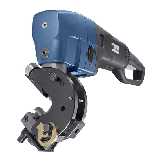
Page 7: Description
Stripper TruTool TKF 1500 beveler (3A1), (3B1) Fig. 84792 Intended use The TRUMPF TruTool TKF 1500 beveler (3A1), (3B1) is an elec- trical powered hand-held device designed for the following appli- cations: ■ Preparation of all K-, V-, X-and Y-shaped welding grooves... -
Page 8: Technical Data
"upside-down position" (carrier above the machine), which is of advantage in particular when bevelling X and K welding joints. The TRUMPF TruTool TKF 1500 beveler (3B1) also offers 2- gear changing for modifying the working speed when machining high-tensile materials. - Page 9 TruTool TKF 1500 (3A1) Other countries Values Smallest radius with 55 mm 2.17 in inner cutouts Safety classSafety class II / II / Tab. 1 TruTool TKF 1500 (3B1) Other countries Values Voltage 230 V 120 V 110 V 120 V 220 V (China) Frequency...
-
Page 10: Icons
Icons Note The following symbols are important for reading and understand- ing the operator's manual. The correct interpretation of the sym- bols will help you operate the machine better and safer. Icon Name Description Read operator's manual Read the operator's manual and safety information in their entirety before starting up the machine. - Page 11 Notes ■ The specified vibration emission value was measured in accordance with a standardized testing procedure and can be used to compare one electric tool with another. ■ The specified vibration emission value can also be applied for a provisional estimate of the vibration load. ■...
-
Page 12: Setting Work
Setting work Adjusting the ram length Material thickness hs Height of bevel β Angle of bevel Width of bevel Length of bevel Residual height Length of bevel and angle of bevel Fig. 9664 ß 55° 14.5 13.3 12.1 10.8 11.9 10.9 ß... - Page 13 60 Hexagon head screw Reference point 65 Crank sliding block Fig. 10063 1. Undo the hex. screw (60). Note Observe angle of bevel ß. 2. Consult the table to find the desired length of bevel/ram length l and the associated scale value W (see "Tab.
-
Page 14: Adjusting The Angle Of Bevel
Adjusting the angle of bevel Stripper Cap screw Rest plate Clamping plate Clamping screw Supporting arm Spindle for setting the material Hexagon head screw thickness Fig. 84793 Notes ■ With stripper (1), the angle of bevel "ß" is continuously adjustable between 20° and 45°. With stripper 55°... -
Page 15: Setting Material Thickness
Setting material thickness 1. Position the machine on the sheet (working position). 2. Undo the clamping screw (4). 3. Adjust the rest plate (3) to match the material thickness using the spindle (5). Allow for 0.5 to 1 mm of play when doing so. - Page 16 Cutting tool Default High-tensile Aluminum High-tensile Heavy-duty cut- 5575 ting tool Regrinding dia- gram Regrinding 10 mm 10 mm 10 mm 10 mm 2 mm reserve Cutting tools for TruTool TKF 1500 beveler Tab. 7 Note Optimum utilzation of the high-performance cutting tool is ensured only with the machine in the 2-gear version.
-
Page 17: Adjusting Height Of The Cutting Tool
Adjusting height of the cutting tool Eccentric shaft Pressure die Clamping screw Carrier Cutting tool Sliding sleeve Fig. 84871 Adjust the height of the cutting tool in such a way that it pro- trudes approximately 1 mm (min. 0, max. 3 mm) out of the slid- ing sleeve (6). -
Page 18: Select Gear
Select gear Note Depending on the material thickness, strength and type of work- piece, a different gear must be selected for machining. Instead of in 2nd gear, 1st gear can always be worked with, but never vice versa. Damage to property due to turning the gear switch during CAUTION operation. -
Page 19: Accessories Included
Accessories included Securing the chip box Chips that fall away during machining are collected in the chip box. Screw Chip box Locking bar Fig. 54642 1. Push the chip box (3) onto the clamping plate. 2. Loosen screw (1). 3. Turn the locking bar (2) downward. 4. -
Page 20: Handle Base
Handle base Screws (M10x30) Handle base Fig. 42381 Ø Tighten screws (1). Tube-shaped handle Tube-shaped handle Screws (M10x20) Fig. 41795 Note Do not use washers. Ø Tighten the tube-shaped handle with a screw (2). Setting work E1026en03... -
Page 21: Roller Holder
Roller holder Screws Roller holder Roller holder on the right-hand side Fig. 41794 The roller holder on the right-hand side is delivered with the machine as standard. A roller holder for the left-hand side can be ordered separately. Roller holder without handle 1. -
Page 22: Options
Options Roller holder for pipe and tube processing The roller holder below can be used to bevel tubes with an out- side diameter of up to 200 mm. The minimum tube inside diam- eter must be 100 mm. For roller holder for tubes with an outside diameter of up to Fig. -
Page 23: Special Tool For Pipe And Tube Processing
Installing the roller holder Adjusting screw (2x) Screws (M12) Stripper Spacer Roller holder Fig. 54706 1. Undo and remove both of the screws on the stripper (2) using the screwdriver provided. 2. Screw on the special stripper for the pipe and tube process- ing (order number 0023242). - Page 24 Supporting body Hexagon head screw Screws Set screw Special tool Screw Stripper Set screw Pressure die For roller holder for tubes with an inside diameter of Fig. 54265 30-120 mm Removing the guide bracket 1. Undo and remove both of the screws on the stripper using the screwdriver provided.
-
Page 25: Conversion Kits For Large Material Thick
14. Set the wall thickness using the set screw (9). 15. Adjust the chamfer size via the set screw (7). 16. Tighten screws (6) and (8) again after making the adjust- ment. In order for the machine to run better: insert the roller holders for tube processing. - Page 26 Converting the machine for material thicknesses > 40 Spacer with cap screw Fig. 54264 1. Loosen cap screw. 2. Remove the block with spindle. 3. Attach the corresponding spacer with spindle. 4. Tighten the cap screw with a moment of 250 Nm. In order for the machine to run better: insert the roller holders for tube processing.
-
Page 27: Suspension Bracket
Suspension bracket Clamping screw Suspension bracket Fig. 54644 Ø In order to install the suspension bracket on the handle base: screw in the clamping screw (1) in the recess. E1026en03 Setting work... -
Page 28: Workstation
Workstation The workstation in which the TKF 1500 beveler can be fastened is used for machining small workpieces. The workstation can be mounted on a base plate or on a pedes- tal. The pedestal must be fastened into the floor using a mounting hole. - Page 29 Mounting the machine at a workstation Threaded hole Fig. 84873 Ø Fasten the machine to the work station using the screw in the threaded hole (1). E1026en03 Setting work...
-
Page 30: Operation
Operation Working with TruTool TKF 1500 (3A1), (3B1) Damage to property due to turning the gear switch during CAUTION operation. Damage to the gearbox can be a consequence. Ø Use the gear switch only when the motor is running down or at rest. - Page 31 − Slide the machine along the sheet in such away that the machine axis is roughly parallel to the sheet edge. − Press the machine against the sheet edge while doing Switching off the machine 5. Press the On/Off switch (1). E1026en03 Operation...
-
Page 32: Maintenance
Machine does not work properly. Ø Maintenance may be carried out by trained specialist techni- cians only. Ø Only use original TRUMPF accessories. Damage to property caused by blunt tools! CAUTION Machine overload. Ø Check the cutting edge of the cutting tool every hour for wear or in the event of poor cutting behavior or poor work result. -
Page 33: Changing The Cutting Tool
Notes ■ Maintain the minimum length of the cutting tools (see "Tab. 7", pg. 14). ■ Do not use shorter cutting tools. ■ Dress the cutting edge with an oil stone after regrinding. Ø If both cutting edges are blunt, regrind the cutting tool on the grinding face. -
Page 34: Change The Sliding Sleeve
Conical bolt Lubricate the grease nipple with a grease gun Cutting tool "S1" lubricating grease Carrier Fig. 85001 1. Release conical bolt (1) 2. Rotate carrier (3) by 45°. 3. Pull carrier out towards the bottom. 4. Screw out the cutting tool (2). 5. - Page 35 18 Push-in flat lubricating nipple 22 Sliding sleeve 20 Supporting body 23 Cap screw 21 Washer 28 Pressure die Sliding sleeve Fig. 9658 1. Release the conical bolt. 2. Rotate supporting body (20) by 45°. 3. Pull the carrier out towards the top. 4.
- Page 36 Accessories and consumables TruTool TKF 1500 (3A1), (3B1) Order number Scope of deliv- 1x standard cutting tool (TruTool TKF 1500 3A1) 2278672 1x high-tensile cutting tool (TruTool TKF 1500 3B1) 2278688 1x aluminum cutting tool 2278690 1x heavy-duty cutting tool...
- Page 37 3. Specify the complete shipping information: − Correct address. − Desired delivery type (e.g. air mail, courier, express mail, ordinary freight, parcel post). Note For TRUMPF service addresses, see www.trumpf‑powertools.com. 4. Send the order to the TRUMPF representative office. E1026en03 Accessories and consumables...
- Page 38 Appendix: Declaration of conformity, guarantee, replacement parts lists Appendix: Declaration of conformity, guarantee, E1026en03 replacement parts lists...
Need help?
Do you have a question about the TruTool TKF 1500 3A1 and is the answer not in the manual?
Questions and answers