Table of Contents
Advertisement
Quick Links
Advertisement
Table of Contents

Related Manuals for Trumpf TruTool TKF 1500


Summary of Contents for Trumpf TruTool TKF 1500
- Page 1 Operator's manual TruTool TKF 1500 (1A1), (1B1)
-
Page 2: Table Of Contents
Special tool for pipe and tube processing Conversion kits for large material thick- nesses Suspension bracket Workstation Operation Working with TruTool TKF 1500 (1A1), (1B1) Maintenance Regrinding cutting tool Changing the cutting tool Change the sliding sleeve Table of contents... - Page 3 Accessories and consumables Ordering consumables Appendix: Declaration of conformity, guar- antee, replacement parts lists E681en_02 Table of contents...
-
Page 4: Safety
30 mA when using the electric tool outside. Protect the machine cable in areas where there are sparks. Ø Only use original TRUMPF accessories. Ø Damage to the machine due to improper handling. WARNING Wear safety glasses, hearing protection, protective gloves Ø... - Page 5 Risk of injury to hands. WARNING Do not reach into the processing line with your hands. Ø Use both hands to hold the machine. Ø Risk of injury from hot and sharp chips! WARNING Chips exit the chip ejector at high speed. Use the chip box.
-
Page 6: Description
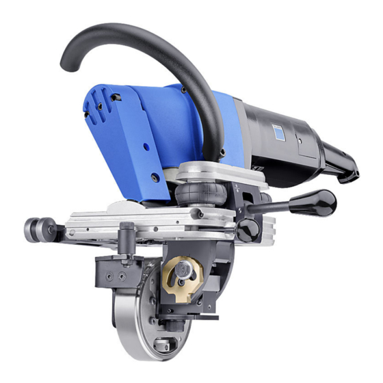
TruTool TKF 1500 beveler (1A1), (1B1) Fig. 13201 Intended use The TRUMPF TruTool TKF 1500 beveler (1A1), (1B1) is an elec- trical powered hand-held device designed for the following appli- cations: Preparation of all K-, V-, X-and Y-shaped welding grooves ■... -
Page 7: Technical Data
"upside-down position" (carrier above the machine), which is of advantage in particular when bevelling X and K welding joints. The TRUMPF TruTool TKF 1500 beveler (1B1) also offers 2- gear changing for modifying the working speed when machining high-tensile materials. - Page 8 TruTool TKF 1500 (1A1) Other countries Values Safety classSafety class II / II / Tab. 1 TruTool TKF 1500 (1B1) Other countries Values Voltage 230 V 120 V 110 V 120 V Frequency 50/60 Hz 50/60 Hz Max. length of bevel "ls" continuously adjustable:...
-
Page 9: Symbols
Symbols Note The following symbols are important for reading and understand- ing the instruction manual. The correct interpretation of the sym- bols will help you operate the machine better and safer. Symbol Name Meaning Read operating manual Read the operator's manual and safety information in their entirety before starting up the machine. - Page 10 The specified vibration emission value can also be applied ■ for a provisional estimate of the vibration load. ■ Times during which either the machine is switched off or run- ning but not actually in use can considerably reduce the vibration load during the entire working period.
-
Page 11: Setting Work
Setting work Adjusting the ram length Material thickness hs Height of bevel β Angle of bevel Width of bevel Length of bevel Residual height Length of bevel and angle of bevel Fig. 9664 ß 55° 14.5 13.3 12.1 10.8 11.9 10.9 ß... - Page 12 60 Hexagon head screw Reference point 65 Crank sliding block Fig. 10063 1. Undo the hex. screw (60). Note Observe angle of bevel ß. 2. Consult the table to find the desired length of bevel/ram length l and the associated scale value W (see "Tab.
-
Page 13: Adjusting The Angle Of Bevel
Adjusting the angle of bevel 23 Clamping screw 43 Rest plate 24 Stripper 49 Cap screw 36 Supporting arm 50 Clamping plate 37 Spindle for setting the material 61 Hexagon head screw thickness Fig. 38120 Notes ■ With stripper (24), the angle of bevel "ß" is continuously adjustable between 20°... -
Page 14: Setting Material Thickness
Setting material thickness 1. Position the machine on the sheet (working position) (see "Fig. 38120", pg. 13). 2. Undo the clamping screw (23). 3. Adjust the rest plate (43) to match the material thickness using the spindle (37). Allow for 0.5 to 1 mm of play when doing so. -
Page 15: Adjusting Height Of The Cutting Tool
10 mm 10 mm 10 mm 2 mm reserve Cutting tool for TruTool TKF 1500 beveler (1A1), (1B1) Tab. 7 Note Optimum utilzation of the high-performance cutting tool is ensured only with the machine in the 2-gear version. Adjusting height of the cutting tool... -
Page 16: Select Gear
3. Rotate the carrier (20) by 360° as often as needed until the cutting tools protrudes 0-3 mm out of the sliding sleeve (22). 4. One rotation (360°) corresponds to a height adjustment of 1.75 mm. 5. Retighten the clamping screw (7). Select gear Note Depending on the material thickness, tensile strength and type of... -
Page 17: Accessories Included
− Press the release switch (3). − Press the On switch (1) and Off switch (2) at the same time. 3. While the motor is running down, turn the gear switch to the desired position. Accessories included Securing the chip box Chips that fall away during machining are collected in the chip box. -
Page 18: Handle Base
Handle base Screws (M10x25) Handle base Fig. 42381 Ø Tighten screws (1). Tube-shaped handle Tube-shaped handle Screws (M10x20) Fig. 41795 Note Do not use washers. Ø Tighten the tube-shaped handle with a screw (2). Accessories included E681en_02... -
Page 19: Roller Holder
Roller holder Screws Roller holder Roller holder on the right-hand side Fig. 41794 The roller holder on the right-hand side is delivered with the machine as standard. A roller holder for the left-hand side can be ordered separately. Roller holder without handle 1. -
Page 20: Options
Options Roller holder for pipe and tube processing The roller holder below can be used to bevel tubes with an out- side diameter of up to 200 mm. The minimum tube inside diam- eter must be 100 mm. For roller holder for tubes with an outside diameter of up to Fig. -
Page 21: Special Tool For Pipe And Tube Processing
Installing the roller holder Adjusting screw (2x) Screws (M12) Stripper Spacer Roller holder Fig. 54706 1. Undo and remove both of the screws on the stripper (2) using the screwdriver provided. 2. Screw on the special stripper for the pipe and tube process- ing (order number 0023242). - Page 22 Supporting body Hexagon head screw Screws Set screw Special tool Screw Stripper Set screw Pressure die For roller holder for tubes with an inside diameter of Fig. 54265 30-120 mm Removing the guide bracket 1. Undo and remove both of the screws on the stripper using the screwdriver provided.
-
Page 23: Conversion Kits For Large Material Thick
16. Tighten screws (6) and (8) again after making the adjust- ment. In order for the machine to run better: insert the roller holders for tube processing. Conversion kits for large material thicknesses Possible damage to property as a result of defective cap CAUTION screws Spacers with longer cap screws are used for greater... - Page 24 Converting the machine for material thicknesses > 40 Spacer with cap screw Fig. 54264 1. Loosen cap screw. 2. Remove the block with spindle. 3. Attach the corresponding spacer with spindle. 4. Tighten the cap screw with a moment of 250 Nm. In order for the machine to run better: insert the roller holders for tube processing.
-
Page 25: Suspension Bracket
Suspension bracket Clamping screw Suspension bracket Fig. 54644 Ø In order to install the suspension bracket on the handle base: screw in the clamping screw (1) in the recess. E681en_02 Options... -
Page 26: Workstation
Workstation The workstation in which the TKF 1500 beveler can be fastened is used for machining small workpieces. The workstation can be mounted on a base plate or on a pedes- tal. The pedestal must be fastened into the floor using a mounting hole. - Page 27 Mounting the machine at a workstation Threaded hole Fig. 54705 Ø Fasten the machine to the workstation using the screw in the threaded hole (1). E681en_02 Options...
-
Page 28: Operation
Off switch Fig. 9659 1. Performing setting work . 2. For TruTool TKF 1500 (1B1): select gear. 3. Press release switch (3) and On switch (1). On switch (1) remains engaged. The motor is running. 4. To switch the instantaneous connection: press the release switch (3), then press the On switch (1) and Off switch (2) together at the same time. - Page 29 − Place machine on the sheet and at first maintain a few centimetres clearance between the cutting tool and the sheet edge. − Push the machine carefully as far as possible against the sheet edge i. e. "piercing". − Slide the machine along the sheet in such away that the machine axis is roughly parallel to the sheet edge.
-
Page 30: Maintenance
WARNING Machine does not work properly. Maintenance may be carried out by trained specialist techni- Ø cians only. Only use original TRUMPF accessories. Ø Damage to property caused by blunt tools! CAUTION Machine overload. Check the cutting edge of the cutting tool every hour for Ø... -
Page 31: Changing The Cutting Tool
Dress the cutting edge with an oil stone after regrinding. ■ Ø If both cutting edges are blunt, regrind the cutting tool on the grinding face. Changing the cutting tool Electrical voltage! Risk of fatal injury due to electric shock. DANGER Remove the plug from the plug socket before undertaking Ø... -
Page 32: Change The Sliding Sleeve
Cutting tool 20 Carrier Clamping screw "S1" lubricating grease 18 Lubricate the grease nipple with a grease gun Fig. 20849 1. Undo the clamping screw (7). 2. Rotate supporting body (20) by 45°. 3. Pull supporting body (20) out towards the bottom. 4. - Page 33 18 Push-in flat lubricating nipple 22 Sliding sleeve 20 Supporting body 23 Cap screw 21 Washer 28 Pressure die Sliding sleeve Fig. 9658 1. Loosen the clamping screw (7). 2. Rotate supporting body (20) by 45°. 3. Pull the carrier out towards the top. 4.
- Page 34 Standard cutting tool TruTool TKF 1500 (1A1) 0088503 Standard cutting tool, 2-pack 1263021 Standard cutting tool, 10-pack 1263029 Cutting tool for high-tensile materials TruTool TKF 1500 (1B1) 0089335 Cutting tool for high-tensile materials, double set 1264417 Cutting tool for high-tensile materials, 10-pack 1264418...
- Page 35 3. Specify the complete shipping information: − Correct address. − Desired delivery type (e.g. air mail, courier, express mail, ordinary freight, parcel post). Note For TRUMPF service addresses, see www.trumpf‑powertools.com. 4. Send the order to the TRUMPF representative office. E681en_02 Accessories and consumables...
- Page 36 Appendix: Declaration of conformity, guarantee, replacement parts lists Appendix: Declaration of conformity, guarantee, E681en_02 replacement parts lists...
Need help?
Do you have a question about the TruTool TKF 1500 and is the answer not in the manual?
Questions and answers