Table of Contents
Advertisement
Advertisement
Table of Contents

Subscribe to Our Youtube Channel
Related Manuals for Trumpf TruTool TF 350


Summary of Contents for Trumpf TruTool TF 350
- Page 1 Operator's manual TruTool TF 350 (1A5) Recharger CLi English...
-
Page 3: Table Of Contents
Selecting the tool ...............10 Selecting tools for ventilation duct construction....13 Loading the rechargeable battery........14 Changing the battery ............17 Operation ................18 Working with the TruTool TF 350 ........19 Joining materials..............22 Information concerning the workpiece and the joint ................23 Selecting processing strategy..........26 Slewing ring (optional) ............28... -
Page 4: Safety
Warning Damage to property due to improper handling. The machine will be damaged or destroyed. Have servicing and inspections of hand-held electric tools Caution and recharger carried out by a qualified specialist. Only use original TRUMPF accessories. Safety E623EN_01.DOC... -
Page 5: Specific Safety Information
Specific safety information Risk of injury due to improper handling. Make sure the machine is always in a stable position when operating it. Warning Never touch the tool while the machine is running. Always operate the machine away from your body. Risk of injury to hands. -
Page 6: Description
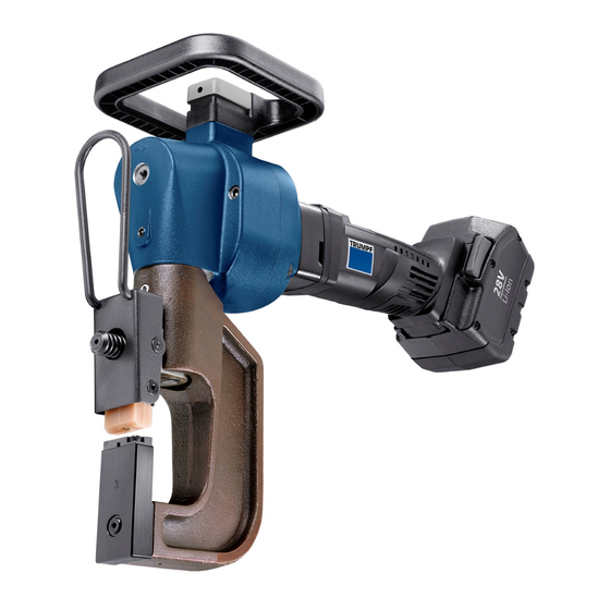
Description Handle Tilting arm for the punch (complete) On/Off switch Button for triggering the stroke Die arm, fixed Rechargeable battery Eccentric shaft Tool carrier 10 Recharger CLi Grease nipple Jointing press TruTool TF 350 with recharger Fig. 53305 Description E623EN_01.DOC... - Page 7 Tilting arm Spring element Die arm TruTool TF 350, dimensions on the tool carrier Fig. 13208 Description E623EN_01.DOC...
-
Page 8: Intended Use
Only use the machine for work and materials described in "Intended use". Warning Do not process materials containing asbestos. The TRUMPF jointing press TruTool TF 350 is an electric hand tool used for the following applications: • Connecting sheet metal parts in overlapping alignment by means of a cold forming process. -
Page 9: Technical Data
Min. edge spacing 8 mm 0.315 in Max. edge spacing 58 mm 2.28 in Technical data of TruTool TF 350 Table 1 Voltage 28 V Loading time at 28 V approximately 1 h Weight without power cord 700 g... -
Page 10: Setting Work
Setting work Selecting the tool The TruTool TF 350 jointing press can be equipped with tools in various ways depending on the particular application. Five different types of dies are available to make it possible to utilize tools corresponding to different types of materials and material thicknesses. - Page 11 Example 1 Max. total material thickness [mm] Steel up to 400 N/mm² 0.8-1.5 1.6-2.0 2.1-2.5 2.6-3.0 3.0-3.5 Steel up to 600 N/mm² 0.8-1.5 1.6-2.0 2.1-2.5 Non-ferrous heavy metal to 0.8-1.0 1.1-2.0 2.1-3.0 3.1-4.0 250 N/mm² Die arm label Die no. (order no.) (0111969) (0111968)
- Page 12 Example 2 Max. total material thickness [mm] Steel up to 400 N/mm² 0.8-1.5 1.6-2.0 2.1-2.5 2.6-3.0 3.0-3.5 Steel up to 600 N/mm² 0.8-1.5 1.6-2.0 2.1-2.5 Non-ferrous heavy metal to 0.8-1.0 1.1-2.0 2.1-3.0 3.1-4.0 250 N/mm² Die arm label Die no. (order no.) (0111969) (0111968)
-
Page 13: Selecting Tools For Ventilation Duct Construction
Selecting tools for ventilation duct construction Whether or not the joint faces inwards (optical reasons) or outwards (fluidic reasons) depends on the respective tool set selected for application. The "Plate for channel" makes it possible to have the jointing on the flange profiles. -
Page 14: Loading The Rechargeable Battery
Loading the rechargeable battery Risk of fatal injury from electric shock. Line voltage is present at the battery terminals. Do not touch the electrical contacts (battery terminals) on the Danger recharger. The rechargeable battery is partially charged (50%) at the time the rechargeable battery electric tool is delivered. - Page 15 Loading the rechargeable Before using the cordless electric tool, a new exchangeable battery or one that has not been used for a long time needs to be charged. battery Note The full capacity is reached after 2-10 charging cycles. Fig. 53300 Insert the exchangeable battery into the insertion well on the recharger.
- Page 16 Status display on the recharger Status display Recharger CLi Fig. 53306 Display Function Red continuous Loading Green continuous Rechargeable battery is full Red, flashing Rechargeable battery too warm/cold Flashing red and green Error in the rechargeable battery Table 7 Setting work E623EN_01.DOC...
-
Page 17: Changing The Battery
Changing the battery Removing the exchangeable Press the locking mechanism (1) together and pull the battery exchangeable battery out and upwards. Inserting the exchangeable Slide the exchangeable battery into the machine holder from battery above until the battery locks into place. Locking mechanism Fig. -
Page 18: Operation
Operation Risk of injury due to improper handling. Make sure the machine is always in a stable position when operating it. Warning Wear safety glasses, hearing protection, protective gloves and work shoes when working at the machine. Never touch the tool while the machine is running. Always operate the machine away from your body. -
Page 19: Working With The Trutool Tf 350
Working with the TruTool TF 350 Damage to property possible as a result of unnecessarily long engine running times. Switch the machine off once the processing of the workpiece has been completed. Caution Before using the cordless electric tool, a new exchangeable battery or one that has not been used for a long time needs to be activated. - Page 20 Rechargeable battery Li-Ion Energy 28 V Fig. 53294 Working with the Triggering the stroke: TruTool TF 350 Actuate the button (2) which is located inside the handle (3). If full revolution speed has been reached, trigger the stroke. Operation E623EN_01.DOC...
- Page 21 Correct holding of the machine Fig. 10049 Switching off Move the On/Off switch (1) to the rear. Operation E623EN_01.DOC...
-
Page 22: Joining Materials
Joining materials Punch Cutting segment Material, punching side Anvil Material, die side Tool and workpiece arrangement Fig. 10043 Cutting Fig. 10044 Forming Fig. 10045 Note Additional cutting and extruding merge together seamlessly during the course of the stroke movement. Operation E623EN_01.DOC... -
Page 23: Information Concerning The Workpiece And The Joint
Information concerning the workpiece and the joint Punching side Thinner workpiece Thicker workpiece Die side Fig. 50427 1. Adjust the set of tools to match the material thickness actually present. 2. In case of different material thicknesses, the thinner workpiece has to be on the die side. - Page 24 Joint Die side Joint width (= control dimension) Joint Punching side Fig. 50428 Total material thickness Control dimension X 1.0 - 2.5 mm 3.3 - 4.5 mm 2.6 - 3.5 mm 3.8 – 4.5 mm Table 9 Operation E623EN_01.DOC...
- Page 25 Distance of the joints from the edge of the material Minimum edge spacing of the joint Fig. 50429 The middle of the joint has to be at least 8 mm from the edge of the material. Otherwise, a joint of lesser quality will be created. Operation E623EN_01.DOC...
-
Page 26: Selecting Processing Strategy
Selecting processing strategy Die and punch can be arranged in two different directions. Load example: shear diagonal, maximum shear strength Load example: shear lengthwise, 50% of the maximum shear strength Fig. 50431, 50432, 10051, 10052 Operation E623EN_01.DOC... - Page 27 Maximum transferable shear force Breaking load in N Tensile strength of the material Individual material thickness in N/mm² in mm Max. shear force that can be transferred depending on Fig. 50430 the material thickness and the tensile strength of the material A maximum shear strength is achieved from bonding two materials which each have:...
-
Page 28: Slewing Ring (Optional)
(3) and tighten the screw (2). The suspension of the slewing ring is done over as eyelet (total weight of the machine TruTool TF 350 with slewing ring is 15 kg). A balancer is used to provide optimal handling. -
Page 29: Stand Trutool Tf 350 (Optional)
STAND TruTool TF 350 (optional) The joining station (order no. 1224803) is used for the stationary operation of the TruTool TF 350 jointing press. This allows small workpieces to be joined quickly and easier. TruTool TF 350 with joining station Fig. -
Page 30: Maintenance
Maintenance Risk of injury from the rechargeable battery. Remove rechargeable battery when changing tools and before performing any maintenance work on the machine. Warning Risk of injury due to incorrect repair work. Machine does not work properly. Repair work may only be carried out by a qualified technician. Warning Damage to property caused by blunt tools. -
Page 31: Replacing The Tool
Replacing the tool If the punch and/or the die are blunt, then they must be replaced. 44 Cup spring (0030678) 105 screw (fixed arm) (0111976) 103 Spring element (tilting arm) (0249303) Fig. 13212 Mounting the workpiece on the machine 1. Clean the tool adapter. 2. - Page 32 Replace punch arm Screw (0013897) Plastic stripper (0053649) Punch (0110335) Fixed punch arm Fig. 50440 1. Remove the complete punch arm from the machine. 2. Remove the stripper (3). 3. Undo the screw (1). 4. Pull out punch (2). 5. Install new punch. 6.
- Page 33 Screw (0983151) Plastic stripper (0053649) Punch (0110335) Tilting arm to punch Fig. 50441 1. Pull the bracket towards the front and swivel the whole tilting arm so that the screw (1) can be accessed. 2. Remove the stripper (3). 3. Undo the screw (1). 4.
- Page 34 Replace die arm Cap screw (0014400) Plate (0063977) Fixed die arm Fig. 50442 1. Remove the complete fixed die arm from the machine. 2. Loosen the cap screw (3). 3. Remove the plate (2). 4. Remove the die (1). 5. Install new die (be sure that the cutting segments fit closely to the anvil, see Fig.
- Page 35 Cap screw (0014400) Plate (0063977) Tilting arm for die Fig. 50443 1. Pull the bracket towards the front and swivel the whole fir arm so that the cap screw (3) can be accessed. 2. Loosen cap screw (3). 3. Remove the plate (2). 4.
- Page 36 Cutting segment installed with a close fit Cutting segment fits closely Fig. 50444 Cutting segment incorrectly installed Cutting segment incorrectly installed Fig. 50445 Maintenance E623EN_01.DOC...
-
Page 37: Lubricating The Ram
Lubricating the ram 53 Grease nipple Fig. 50446 The tool ram must be lubricated through the grease nipple (53) every 20 operating hours with a grease gun. Maintenance E623EN_01.DOC... -
Page 38: Lubricating The Coupling
Lubricating the coupling Lubrication interval: every 20 operating hours. 1. Pull the rechargeable battery off the machine. 2. Unscrew the screw plug (1). Screw plug Fig. 50449 3. Press and hold the button for stroke triggering (2) and rotate the eccentric shaft (3) clockwise (see arrow at the machine's face end) until the lubrication port becomes visible. - Page 39 Button for stroke triggering Screwdriver at the eccentric (0053272) shaft (0110344) Fig. 50448 4. Relubricate the coupling with the grease gun (4) through the lubrication port (5) (one stroke). Grease gun filled with "G1" Lubrication port special (1398728) Fig. 50447 5.
- Page 40 6. Put the machine in a safe position. 7. Insert the rechargeable battery. 8. Switch on the motor. The machine completes the stroke which was manually started. 9. Press the button for stroke triggering and trigger a test stroke. Maintenance E623EN_01.DOC...
-
Page 41: Original Accessories And Wearing Parts
0243189 Punching and nibbling oil for steel 0103387 (0.5 l) Punching and nibbling oil for aluminum 0125874 (1 l) Slewing ring TruTool TF 350 0976671 STAND TruTool TF 350 1224803 Rechargeable battery 28 V 1464697 Recharger CLi 220-240 V 1464702... - Page 42 3. Specify the complete shipping information: Correct address. – Desired delivery type (e.g. air mail, courier, express mail, – ordinary freight, parcel post). 4. Send the order to the TRUMPF representative office. For TRUMPF service addresses, see www.trumpf-powertools.com. Original accessories and wearing parts E623EN_01.DOC...
Need help?
Do you have a question about the TruTool TF 350 and is the answer not in the manual?
Questions and answers