
Related Manuals for Trumpf TruTool TKF 1500


Summary of Contents for Trumpf TruTool TKF 1500
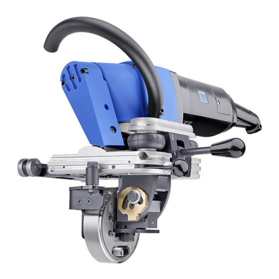
- Page 1 Operator´s manual TruTool TKF 1500 (2C1), (2D1) english www.stampersstore.com admin@productivityresources.com...
-
Page 2: Table Of Contents
Driving rollers Accessories included Pedestal Installing the chip box Operation Overload indicator Working with the TruTool TKF 1500 Maintenance Installing and disassembling the drive unit Changing the cutting tool Disassembling the cutting tool Installing and setting the cutting tool Regrinding cutting tool... -
Page 3: Table Of Contents
Accessories and consumables Ordering consumables Help in the case of problems Appendix: Guarantee, declaration of con- formity, replacement parts lists E612EN_02 2011-08-22 Table of contents... -
Page 4: Safety
30 mA when using the electric tool out- side. Ø Protect the machine cable in areas where there are sparks. Ø Only use original TRUMPF accessories. Damage to the machine due to improper handling. WARNING Ø Wear safety glasses, hearing protection, protective gloves and work shoes when working at the machine. - Page 5 Risk of injury to hands. WARNING Ø Do not reach into the processing line with your hands. Ø Use both hands to hold the machine. Risk of injury from hot and sharp chips! WARNING Chips exit the chip ejector at high speed. Ø...
-
Page 6: Description
Grease nipple TruTool TKF 1500 beveler (2C1), (2D1) Fig. 56390 Intended use The TRUMPF TruTool TKF 1500 beveler (2C1), (2D1) is an electrical powered hand-held device designed for the following applications: ■ Preparation of all K-, V-, X-and Y-shaped welding grooves... -
Page 7: Technical Data
■ Beveling of edges on large, bulky workpieces by using the beveler as a hand-held device. The TRUMPF TruTool TKF 1500 beveler (2D1) also offers 2- gear changing for modifying the working speed. Technical data TruTool TKF 1500 (2C1) -
Page 8: Symbols
TruTool TKF 1500 (2D1) Other countries Values Working speed 1.25 m/min (1st gear) 4.1 ft/min (1st gear) 2 m/min (2nd gear) 6.55 ft/min (2nd gear) Nominal power con- 2000 W sumption Nominal current 15 A Stroke rate with nominal 230/min... -
Page 9: Noise And Vibration Information
Symbol Name Meaning .../min Revolutions/strokes per minute Revolution speed, stroke rate per minute Tab. 3 Noise and vibration information Noise emission value may be exceeded. WARNING Ø Wear hearing protection. Vibration emission value may be exceeded. WARNING Ø Select tools correctly and replace them promptly when they show wear. -
Page 10: Setting Work
Setting work Damage to property due to improper handling. CAUTION Collisions could result from an erroneous setting of the machine. Ø Rotate the eccentric shaft one full turn in a clockwise direc- tion using the Allen key provided. If no collisions can be detected, remove the Allen key and put the machine into operation in accordance with regulations. -
Page 11: Adjusting The Angle Of Bevel
■ If the pressure in the bellows is too high, then a very high drive force will be required and the drive will display an over- load. If this is the case, then the pressure in the bellows can be reduced down as far as 6 bar. Damage to property due to improper handling. -
Page 12: Adjusting The Ram Length
Impeller 36 Hex. screw 35 Spindle for setting the material thickness Fig. 56393 1. Undo the hex. screw (36). 2. Set the desired angle in accordance with the scale. 3. Retighten the hex. screw (36). Adjusting the ram length Material thickness hs Height of bevel β... - Page 13 ß 55° 14.5 13.3 12.1 10.8 11.9 10.9 ß 45° 13.6 12.12 10.8 10.6 10.6 ß 37.5° 15.5 13.8 12.2 10.5 12.3 ß 30° 11.2 ß 20° 12.2 11.4 ß Angle of bevel b Width of bevel Length of bevel W Scale value which must be adjusted on the crank sliding block h Height of bevel...
-
Page 14: Setting Material Thickness
Stop roller 19 Crank sliding block 17 Pressure die Reference point 18 Hex. screw Fig. 56392 1. Undo the hex. screw (18). 2. Consult the table to find the desired length of bevel/ram length l and the associated scale value W (see "Tab. -
Page 15: Selecting Cutting Tool
= 7° x = 15° Regrinding 10 mm reserve Regrinding dia- gram Cutting tools for the TruTool TKF 1500 beveler (2C1), (2D1) Tab. 7 Assembly and setting work: (see "Changing the cutting tool", pg. 25). E612EN_02 2011-08-22 Selecting cutting tool... -
Page 16: Driving Rollers
"Tab. 5", pg. 13). ■ It is not possible to refinish the bevel. Driving rollers for the TruTool TKF 1500 beveler (2C1), (2D1) Tab. 8 Assembly: (see "Changing the driving roller", pg. 30). Accessories included Pedestal Fig. -
Page 17: Installing The Chip Box
The machine can be stored on the pedestal when it is not in use. Installing the chip box Chips that fall away during machining are collected in the chip box. Locking bar Chip box Machine with chip box Fig. 56396 1. -
Page 18: Operation
Operation Damage to the machine due to improper handling. WARNING Ø Make sure the machine is always in a stable position when operating it. Ø Never touch the tool while the machine is running. Ø Always operate the machine away from your body. Ø... -
Page 19: Overload Indicator
Component Steel Punching and nibbling oil (0.5 l, Order No. 0103387) Aluminum Punching and nibbling oil for aluminum (1 l, Order No. 0125874) Tab. 9 Overload indicator Damage to property due to improper handling. CAUTION The machine can become damaged when working with the machine for extended periods when it is overloaded. -
Page 20: Working With The Trutool Tkf 1500
Front rollers 13 On/Off switch Rear rollers 22 Motor handle Placing the machine on the workpiece Fig. 56397 1. Performing setting work (see "Setting work", pg. 10). 2. For TruTool TKF 1500 (2D1): select gear (37). Overload indicator 2011-08-22 E612EN_02... - Page 21 3. Press release switch (23) and On switch (13). On switch (13) remains engaged. The motor is running. 4. To switch the instantaneous connection: press the release switch (23), then press the On/Off switch (13) together at the same time. Note Do not move the machine towards the workpiece until full speed has been reached.
- Page 22 Fig. 56869 8. End of the workpiece: − manually guide the machine again on the end of the workpiece. − Machine stops automatically as soon as the driving roller travels over the end. − Complete machining by setting the feed lever (9) to "0" −...
-
Page 23: Maintenance
Maintenance Electrical voltage! Risk of fatal injury due to electric shock. DANGER Ø Remove the plug from the plug socket before undertaking any maintenance work on the machine. Risk of injury due to incorrect repair work WARNING Machine does not work properly. Ø... -
Page 24: Installing And Disassembling The Drive Unit
Maintenance point Procedure and interval Recommended Lubricant Order lubricants Ventilation slots Clean as needed. Outer brush on the impeller Change or clean as needed. Spindle for setting material Clean as needed. thickness Maintenance positions and intervals Tab. 10 Installing and disassembling the drive unit Damage to property due to improper handling. -
Page 25: Changing The Cutting Tool
2. Remove the drive unit (2). Installing the drive unit 29 Lever 30 Driving roller Fig. 56407 3. Shift lever (29) to the left before assembly. 4. Attach the drive unit, to do this slide the guide (26) onto the nut (28). -
Page 26: Disassembling The Cutting Tool
Damage to property due to improper handling. CAUTION Collisions could result from an erroneous setting of the machine. Ø Rotate the eccentric shaft one full turn in a clockwise direc- tion using the Allen key provided. If no collisions can be detected, remove the Allen key and put the machine into operation in accordance with regulations. -
Page 27: Installing And Setting The Cutting Tool
1. Screw in the cutting tool into the ram (15). Observe the screw-in depth of a = 76.5 ± 0.9 mm. Use a setting gauge (TRUMPF order no.: 1411767) on the handle of the assem- bly tool (36). 2. Align the cutting edge of the cutting tool (12), observing the bevel grind while doing so. -
Page 28: Regrinding Cutting Tool
Regrinding cutting tool Cutting tools are ground at an angle on the grinding face. Observe the corresponding regrinding diagram (see "Tab. 7", pg. 15). Notes ■ Maintain the minimum length of the cutting tools (see "Tab. 7", pg. 15). ■ Do not use shorter cutting tools. - Page 29 Sliding sleeve Grease nipple Supporting body Cap screw Pressure die Washer Fig. 56410 1. Disassemble the drive unit (see "Installing and disassembling the drive unit", pg. 24). 2. Loosen the clamping screw. 3. Turn the gear head by 45°. 4. Pull out the gear head upwards. 5.
-
Page 30: Lubricating The Impeller
Lubricating the impeller Fig. 56411 Before putting the machine into service for the first time or when it has not been used for long periods: Ø Lubricate the inside of the impeller with the universal oil provided (Order No. 0138648). Ø... -
Page 31: Changing The Power Cable
Impeller 32 Roller 29 Lever 33 Screw 30 Driving roller 34 Axis 31 Retaining ring Fig. 54710 Changing the driving roller 1. Set the impeller (8) to the maximum material thickness. 2. Undo the screw (33). 3. Swivel axis (34) downward. 4. -
Page 32: Replacing Carbon Brushes
Note For TRUMPF service addresses, see www.trumpf-power- tools.com. Replacing carbon brushes The motor comes to a standstill whenever the carbon brushes are worn out. Note For TRUMPF service addresses, see www.trumpf-power- tools.com. Ø Change the carbon brushes. Changing the power cable... -
Page 33: Accessories And Consumables
Assembly tool 1424125 Pump 0384723 Box for small parts 0353966 Chip box 0023209 Pedestal 1555593 TruTool TKF 1500 (2C1), (2D1) operator's 1439388 manual Safety information, other countries 0125699 Safety information, USA 1239438 Tab. 11 Ordering consumables Note The following data must be specified in order to ensure that parts are delivered correctly and without delay. - Page 34 Note For TRUMPF service addresses, see www.trumpf‑powertools.com. 4. Send the order to the TRUMPF representative office. Accessories and consumables 2011-08-22 E612EN_02...
-
Page 35: Help In The Case Of Problems
Help in the case of problems Problem Cause Correction The machine does not remain on Cutting tool is blunt. Regrind, replace the cutting tool. the sheet. Incorrectly set material thickness Reset the material thickness, if nec- (too loose). essary remove the burr on the workpiece. -
Page 36: Appendix: Guarantee, Declaration Of Conformity, Replacement Parts Lists
Appendix: Guarantee, declaration of conformity, replacement parts lists Appendix: Guarantee, declaration of conformity, 2011-08-22 E612EN_02 replacement parts lists...
Need help?
Do you have a question about the TruTool TKF 1500 and is the answer not in the manual?
Questions and answers