Table of Contents
Advertisement
Quick Links
Advertisement
Table of Contents

Related Manuals for Trumpf TruTool TKF 700


Summary of Contents for Trumpf TruTool TKF 700
- Page 1 Operator's manual TruTool TKF 700 (1A1) english...
-
Page 2: Table Of Contents
Selecting the angle of bevel ..........13 Configuring workstation (optional) ........14 Mounting and aligning the machine in the workstation..............15 Operation ................18 Working with the TruTool TKF 700........19 Changing the cutting direction ...........20 Maintenance ..............21 Changing the tool...............22 Disassembling the blade ..........23 Cleaning the tool............23... -
Page 3: Safety
Safety Read the Operator's Manual and the general safety rules USA/CAN (Material number 1239438, red document) in their entirety before starting up the machine. Follow precisely the directions contained therein. Rest of the world Read the Operator's Manual and the safety instructions (Material number 125699, red document) in their entirety before starting up the machine. - Page 4 Arrange for start-ups and checks on manual electric tools to be carried out by a trained specialist. Only used the original accessories provided by TRUMPF. Risk of injury from falling machinery! The entire weight of the machine must be taken up after processing of the work workpiece.
-
Page 5: Description
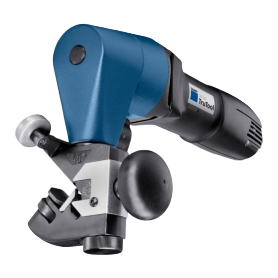
10 Locking mechanism Rest plate On/Off switch 11 Handle Blade Speed controller 12 Chamfer sizes Carrier Red indicator light (LED) "Motor 13 Scale for setting the Chamfer Roller guide overload" size "h " Bevelling machine TruTool TKF 700 Fig. 28207 Description E459EN_05.DOC... -
Page 6: Correct Use
For processing and materials, only use machines which are named in "Correct use". Warning The TRUMPF bevelling machine TruTool TKF 700 is an electric hand tool used for the following applications: • Preparation of all of the K-, V-, X- and Y-shaped welding... -
Page 7: Technical Data
Technical data Tensile strength Angle of bevel 30° 37.5° 45° 400 N/mm² 6 mm (0.236 in) 5.5 mm (0.216 in) 5 mm (0.196 in) 600 N/mm² 5 mm (0.196 in) 4.5 mm (0.177 in) 4 mm (0.157 in) 800 N/mm² 3.5 mm (0.138 in) 3 mm (0.118 in) 3 mm (0.118 in) Max. - Page 8 Rest of the world Values Values Values Values Voltage 230 V 120 V 110 V 120 V Frequency 50/60 Hz 50/60 Hz 50/60 Hz 50/60 Hz Working speed 1.5 m/min 1.5 m/min 1.5 m/min 5 ft/min Nominal power 1400 W 1200 W 1140 W 1200 W...
-
Page 9: Tool Assembly
Tool assembly Setting the number of strokes A reduced number of strokes improves the quality of the work • For machining radiuses. • For tube machining. • For machining steel with a tensile strength > 400 N/mm² (improved service life). Setting wheel for speed controller on motor Speed controller... -
Page 10: Selecting The Blade
Selecting the blade 2 different blades are available for machining sheets of different tensile strengths: Standard High-tensile blade Blade type Material No. 130879 130880 Tensile strength of the up to 400 N/mm² >400 N/mm² material to be machined Example Mild steel, aluminium Chromium steel Table 4 Tool assembly... -
Page 11: Adjusting The Chamfer Size
Adjusting the chamfer size Carrier 34 Chamfer size setting 10 Rest plate Reference edge for the scale of 31 Nut for sheet thickness setting the setting of the chamfer size Fig. 12263 Set the dimension h s "Chamfer size" directly above the scale. Tool assembly E459EN_05.DOC... -
Page 12: Setting The Sheet Thickness
Setting the sheet thickness 1. Place machine on the sheet (work position). 2. Tighten the rest plate (10) to the sheet using the nut (31) and rotate back to the next engagement position (play circa 0.1-0.3 mm). Sheet thickness Angle of bevel "s"... -
Page 13: Selecting The Angle Of Bevel
Selecting the angle of bevel 3 carriers are available with the angles 30° / 37.5° / 45° for the bevelling machine. The selection of the angle is determined by replacing the entire carrier: b = l sin ß h = l cos ß... -
Page 14: Configuring Workstation (Optional)
Do not reach into the area which is covered over by the hand protection device. Warning The workstation in which the TruTool TKF 700 bevelling machine can be fastened is used for machining small workpieces. This workstation, which stands on a non-skid support, must screwed down tightly to a table through mounting holes. -
Page 15: Mounting And Aligning The Machine In The Workstation
Mounting and aligning the machine in the workstation 1. Rotate the machine carrier into the correct position. 2. Fasten the machine in the workstation with the help of the screw (110) (wrench can be found among the accessories). 3. Loosen the two clamping levers (46). 4. - Page 16 130 110 Position Designation Material identification number Trestle 133885 Strip, right 133883 Strip, left 133884 Plate 133886 Clamping levers (2x) 105652 Cap screw M 5x10-12 DIN 912 014524 Lock nut (knurled nut) (2x) 133947 Star grip 133948 Disc 8.4-ST DIN 125 023671 Cap screw M 5x16-12 DIN 912 014540...
- Page 17 12. Clamp the plate (45) tightly with the two clamping levers (46). 13. The workpiece will lie on the plate (45). Note Hold the work piece during machining in such a way that the surface lies on the plate (45) and the sheet edge lies on the strips (41) (42).
-
Page 18: Operation
Operation Damage to property possible due to too-high network voltage! Damage to the motor. Caution Check the power supply. The power supply must correspond to the information on the machine type plate. Danger of injury possible due to improper handling! When working with the machine, always ensure that it has a secure base. -
Page 19: Working With The Trutool Tkf 700
Working with the TruTool TKF 700 Switching on and off On/Off switch Fig. 28208 Move the On/Off switch to the front. Switching on the TruTool TKF 700 Note The cutting result is improved and the service life of the cutting tool increased if the cutting track is coated with oil before machining the workpiece. -
Page 20: Changing The Cutting Direction
Changing the cutting direction In situations where space is limited, the tool and/or the cutting direction can be turned by 90° to the right or to the left. (see Fig. 13470, Pg. 22) 1. Open locking mechanism (15). 2. Rotate die carrier (1) by 90° in the desired direction. 3. -
Page 21: Maintenance
Maintenance Damage to property possible due to blunt tools! Overloading of the machine. Check the cutting edge of the cutting tool hourly for wear. Caution Sharp blades provide good cutting performance and are easier on the machine. Replace blades promptly. Risk of possible injury due to improper repairs! The machine does not function properly. -
Page 22: Changing The Tool
Changing the tool Carrier Clamping screw 15 Locking mechanism Blade Grease gun Fig. 13470 The blade must be replaced if it has become blunt. Maintenance E459EN_05.DOC... -
Page 23: Disassembling The Blade
3. Mount the carrier (1). 4. Close locking mechanism (15). 5. Place grease nipple laterally on the carrier using a grease gun "F" with lubricating grease "G1" TRUMPF Order No. 139440. Note Use only original TRUMPF replacement parts. Replacing carbon brushes The motor comes to a standstill when the carbon brushes are worn out. -
Page 24: Wearing Parts
Required delivery type (e.g. air mail, courier, express mail, – ordinary freight, parcel post). 4. Send the order to the TRUMPF representative office. For TRUMPF service addresses, see the address list at the end of the document. Wearing parts E459EN_05.DOC... -
Page 25: Original Accessories
Original accessories Designation Material No. Blade mounted (for the machining of mild steel) 130879 Handle 131063 Spanner TORX T25 131549 Grease gun 068624 Lubricating grease "G1" 344969 Case 982540 Roller holder 130868 Operator's manual 976203 Safety information (red document), other 125699 countries Safety information (red document), USA... - Page 26 Options E459EN_05.DOC...
Need help?
Do you have a question about the TruTool TKF 700 and is the answer not in the manual?
Questions and answers