Table of Contents
Advertisement
Quick Links
Advertisement
Table of Contents

Related Manuals for Real Flame Vivente VVT75


Summary of Contents for Real Flame Vivente VVT75
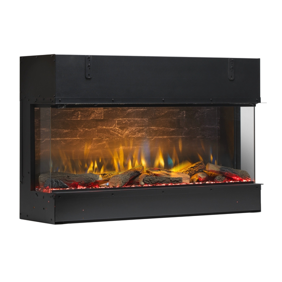
- Page 1 INSTALLATION & OPERATING MANUAL Vivente Landscape Electric Fire Models: VV T75 , V VT1 00, VVT150 The product is compliant with the local electrical standards of all countries where offered for sale by Glen Dimplex and its subsidiaries. 08/54580/0 ISSUE 3.2 OCN 11415...
- Page 2 CAUTION: Please read this information guide carefully to be able to safely install, use and maintain your product. Important Safety Advice When using electrical appliances, basic precautions should always be followed to reduce the risk of fire, electrical shock and injury to persons, including the following: If the appliance is damaged, check with the supplier before installation and operation.
-
Page 3: General Information
Real Flame Vivente Electric Fire Models: VV T 75 , V V T1 0 0 , V V T 1 5 0 Thank you for choosing a Real Flame electric fire. General Information CAUTION: Ensure installation does not allow fire to be in direct contact with building vapour barrier or insulation and meets all local building code. -
Page 4: Installation Instructions
Installation Instructions Step 1: Choosing Installation Type The Vivente can be configured in 4 different ways: • Single-sided – Front glass only (see Fig 1a) • Two-sided Right (see Fig 1b) • Two-sided Left (see Fig 1c) • Three-sided (see Fig 1d). Fig. - Page 5 3. For Front Glass Only setup, repeat Step 2 on the opposite side of product. 4. Assemble the appropriate front Trim to the product. See Fig. 2 (Three different trims are provided with the product to facilitate the various setup options.) Fig.
- Page 6 Fitting Panel – Before Installation (Recommended) 1. Remove side bracket as displayed on Fig. 4 2. The side bracket can be used to take out the back panel. Insert the bottom part of the side bracket into the Back Panel notch, and slide out the back panel (Fig.5). 3.
- Page 7 Fig. 7 Fig. 6 Fig. 8 Fig. 9 Fig. 10a Fig. 10b...
-
Page 8: Step 3: Installing The Product
Step 3: Installing the Product CAUTION: Two people will be required for various steps of this procedure. This product is designed to be installed into existing block wall or a custom-built studded wall structure. Please consult a competent installer before undertaking this to ensure a safe and secure installation. - Page 9 Fig. 11 Unit Dimensions 6 6 6 X + 40MM VVT75-AU VVT100-AU VVT150-AU 1003 1503 Minimum Frameout Dimensions Clearance recommended VVT75-AU VVT100-AU VVT150-AU 1014 1514 200 - 800 Recommended, may be higher or lower to suit desired installation *All measurements are in MM Note 1- While the 150mm clearance is recommended, it is not mandatory and may be reduced if required to suit a particular installation.
-
Page 10: Step 4: Fuelbed Assembly
Fig. 12 Fig. 13a 150mm 200 - 800mm Fig. 13b Fig. 13c Step 4: Fuelbed Assembly A range of fuel bed material has been provided for you to choose your desired look. A set of high-quality ceramic logs enhance the effect of this fire. Please take great care when handling these logs to ensure they do not get dropped or rub against each other, as they are easily marked. - Page 11 media can also be done to create unique fuel bed assembly. 1. Remove front trim on unit. (Fig. 2) 2. Remove Front Glass from product and store in a safe place. (Fig. 6) (A suction cup is provided to help remove/replace the front glass.) 3.
- Page 12 Fig. 15...
- Page 13 VVT75...
- Page 14 VVT100...
- Page 15 VVT150...
-
Page 16: Operation And Use
Operation and Use WARNING: Failure to follow these operating instructions may result in injury and/or damage. Thank you for choosing the Vivente. We hope you enjoy using your new electric fire. Please take a few minutes to read these instructions. This will help you understand and benefit from all of the following features: •... - Page 17 On this setting SmartSense will only switch the flame effect when it detects movement between the hours of 5-11pm, so if you enter the room during the day the fire will not react. However in the evening, your Real Flame fire will instantly switch on your flame effect – remembering your last setting.
- Page 18 Fig. 16 Fig. 17...
- Page 19 Operating Instructions (ON BOARD CONTROLS)- See Figure 16 The unit can be operated using the manual controls which are located on the upper right of the fireplace. See Fig. 17 Icon Function Description Turns product on to Standby mode. When pressed to "I", Display Board show Standby Switch "ST.BY"...
- Page 20 Remote control The fireplace is supplied with a remote control. Operating Instructions using REMOTE CONTROL - See Figure 18 Icon Display Funtion Description Press Once to turn the product on. ("ON") Press a second time to put the product into standby. ("ST.BY" is shown, then "." is displayed "FIRE"...
- Page 21 Fig. 18 A. Power Button B. Time Cycle Switches the product on and off. Restores The timer button increases the timer by to previous setting when switched on. 0.5hrs on each press. Up to 8hrs cycle. C. SmartSense motion sensing cycle Vivente switches on and off depending D.
- Page 22 Product Features Overview Function On Board Controls Remote Control App Control Standby Temperature Adjustment (15 - 32C) Heat Disable Heater Mode (ECO, Boost, Frost Protection, Fan) Flame Intensity Volume Setting Run-back Timer 7 - Day Timer Volume Setting Ambient Light Setting Ambient Light On/Off Customizable Ambient SmartSense...
-
Page 23: Maintenance
Flame effect themes There are different combinations of flame effect available. Different presets of lighting colour combinations are available and can be cycled through using the remote control. Further customisation of the effects is accessible through the smart phone app. Resetting the Temperature Cutoff Switch Should the heater overheat, an automatic cut out will turn the whole unit off and it will not come back on without being reset. -
Page 24: Additional Information
Additional Information CAUTION: Do not use if the heater’s mains power lead is damaged. Such use may cause a hazard. If damaged, the mains power lead must be replaced by the manufacturer or its authorised dealer. Recycling At the end of the electrical products useful life it should not be disposed of with household waste. - Page 25 Website: Telephone: www.realflame.com.au AU: 1300 554 155 www.realflame.co.nz NZ: +64 9 274 8265 This product is protected by Intellectual property rights and patents owned by the Glen Dimplex Group on an international basis. The Glen Dimplex Group of Companies will actively protect these rights. Glen Dimplex.