Table of Contents
Advertisement
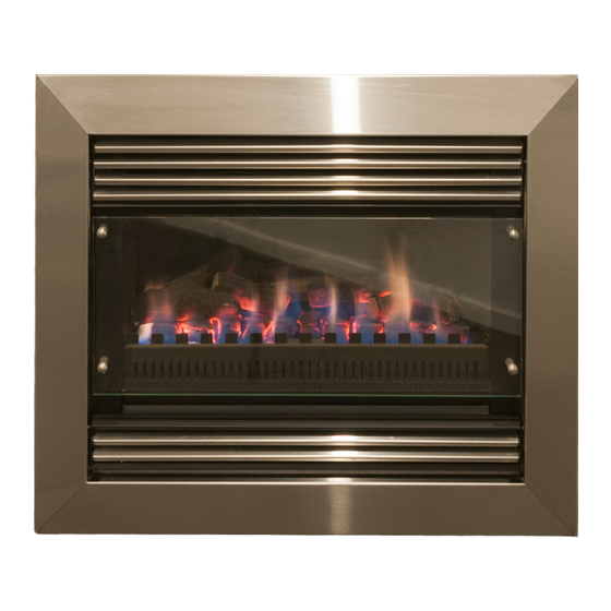
PYROTECH DELUXE
®
INSTALLATION & OPERATING MANUAL
The Pyrotech Deluxe is approved to be installed into a masonry fireplace
or as a zero clearance firebox enclosed by a timber frame & plastered.
The Pyrotech is approved to operate on Natural Gas and Propane (LPG)
gases only. Approval Number GSCS20113.
VERSION 24
Advertisement
Table of Contents

Related Manuals for Real Flame PYROTECH DELUXE


Summary of Contents for Real Flame PYROTECH DELUXE
- Page 1 ® INSTALLATION & OPERATING MANUAL The Pyrotech Deluxe is approved to be installed into a masonry fireplace or as a zero clearance firebox enclosed by a timber frame & plastered. The Pyrotech is approved to operate on Natural Gas and Propane (LPG) gases only.
-
Page 2: Important Safety Notice
WARNING The Pyrotech Deluxe has a primary safety glass fitted in front of the glass door. This safety glass is fitted to this appliance to reduce the risk of injury from burns and at no time should this glass be permanently removed. -
Page 3: Table Of Contents
Removal of control valve ..................18 Removal of Millennium control module .............18 Parts List.........................19 Gas Control Assembly ...................20 Flue Termination Regulations ................21 Remote Control Operating Guide .................22 Optional Marble Surround Installation Procedure ..........25 Optional Mantelpiece Installation Procedure/Dimensions........26 Electrical Diagram....................27 Real Flame Contact Information................28... -
Page 4: Data Plate
DATA PLATE MODEL: PYROTECH DELUXE WEIGHT: 61 kg TYPE INJ/SIZE MJ/H P .T.P . 2 x 1.65mm 1.00kPa HIGH NG PRIMARY 2 x 1.65mm 0.38kPa LOW NG SECONDARY 2 x 1.0mm 2.60kPa HIGH LPG PRIMARY 2 x 1.0mm 0.90kPa LOW... -
Page 5: Inbuilt Model Dimensions/Installation Procedure
PYROTECH INBUILT MODEL • Unit installed into an existing “working” fireplace requires an AGA approved 150mm gas cowl. If the chimney does not draw properly, a 900mm length of flexi flue (supplied with unit) should be fixed to the flue spigot on top of the heater. The flexi flue should be fixed in the vertical position in a manner that does not allow the flue to fall or come away from the spigot. - Page 6 PYROTECH INBUILT MODEL Pyrotech Inbuilt Installation Procedure (continued) Figure (3) Remove nylon grommets and put Figure (4) Remove three spacer bolts, and aside carefully. loosen bolt in bottom right corner. NOTE: Keep coals or pebbles clear of burner rail. Figure (5) Support front glass as shown, and remove fourth spacer bolt.
- Page 7 PYROTECH INBUILT MODEL Pyrotech Inbuilt Installation Procedure (continued) The Pyrotech Space Heater (Natural Gas Only) is approved for use with Pebbles. To install the Pebbles follow the installation instructions as per Figures 1 to 5 above, and then proceed as follows (Figures 10 to 12). Figure (10) Install the metal angle at the rear of Figure (11) Place pebbles between the first row the fireplace and place one row of...
-
Page 8: Zero Clearance Model Timber Frame Installation Procedure
PYROTECH ZERO CLEARANCE MODEL Pyrotech Zero Clearance Timber Frame Installation (Recommended only) (Recommended only) IMPORTANT Install unit and fluing before plasterboard. Plaster to run beyond stud and behind trim HEATER From hearth TRIM Approx 20mm for hearth if required. NOTE: Note: If fire is to be installed off the floor with 4 sided trim, use same A, B, C and D dimensions as shown with frame work included below fire to required height. -
Page 9: Zero Clearance Model
PYROTECH ZERO CLEARANCE MODEL Position the Pyrotech firebox in the selected installation position in the room. You will require the Zero Clearance Kit to suit, which is to be fitted to the main fire box as shown on page 10. ZERO CLEARANCE KIT COMPONENTS No. -
Page 10: Zero Clearance Model Assembly
PYROTECH ZERO CLEARANCE MODEL Fit Zero Clearance Kit to unit as shown below: ITEM 1 ITEM 5 ITEM 2 ITEM 4 ITEM 6 ITEM 3 Secure side strips (Item 1) to side brackets on Place LH side panel (Item 4) in behind lip of fire box using screws (2 off per side strip). -
Page 11: Zero Clearance Model Dimensions/Installation Procedure
PYROTECH ZERO CLEARANCE MODEL Pyrotech Zero Clearance Installation Procedure Connect to gas supply. TICK BOXES Connect to power supply Install flue to 500mm minimum above roof line. (Min total flue run 3.6 m) Plaster to unit with trim removed. Install trim. Assemble unit as per pages 5 - 7. -
Page 12: Dimensional Drawings
DIMENSIONS Pyrotech Inbuilt Pyrotech ZC Trim FRONT - 4 SIDED FRONT - 3 SIDED... -
Page 13: Tests To Be Carried Out By Installer
TESTS TO BE CARRIED OUT BY INSTALLER • Check unit for gas leaks. • Ensure that both high and low pressures are set as per the appliance data plate. Refer Page 20 for adjustment and Test pressure points • Turn the unit on to ensure it operates correctly. •... -
Page 14: Servicing And Maintenance
SERVICING AND MAINTENANCE To follow when servicing, removing fan or changing valve or control modules. IMPORTANT: POWER MUST BE ISOLATED PRIOR TO CARRYING OUT THE SERVICE/MAINENANCE. SERVICE/MAINENANCE ONLY TO BE CARRIED OUT BY AN AUTHORISED PERSON. Figure (1) Remove top louvre panel.The top panel is held by a screw each side. - Page 15 Figure (8) Remove coals/logs or pebbles and Figure (9) securely store to prevent damage. Figure (10) Remove front iron from burner. Figure (11) Remove burner holding screws on each side of burner. Figure (12) Remove log positioning panel Figure (13) Remove log positioning panel. screw at rear of firebox.
- Page 16 Figure (16) Remove burner from firebox Figure (17) Remove the nine screws securing the base to the firebox from the back of the base... Figure (18) ...and the sides of the base. Figure (19) Lift the base plate to expose the flexi burner tube.
-
Page 17: Removal Of Fan
Removal of Fan Figure (1) Remove the wing nuts from each Figure (2) Tilt fan back and slide out. side of fan and remove holding plates. Figure (3) Lift fan out... Figure (4) ...and disconnect power plug to remove fan. Removal of Control Module Figure (1) Remove cover plate from module... -
Page 18: Removal Of Control Valve
Removal of Control Valve Figure (1) Remove valve modulating lead Figure (2) Disconnect gas from control valve. from control valve. Figure (3) Remove wing nuts from each of the control valve holding brackets and remove valve. Removal of Millennium Control Module Figure (1) Remove 3 screws from top of Figure (2) Remove cover from module. -
Page 19: Parts List
PARTS LIST Gas Control Valve Module Box Remote Control Module Remote Control 1. Pilot 2. Pilot Tube 3. Burner Tube... -
Page 20: Gas Control Assembly
GAS CONTROL ASSEMBLY Inlet Test Adjustment Outet Test Pressure Point for High Pressure Point Gas Inlet Gas Outlet Adjustment for Low... -
Page 21: Flue Termination Regulations
PYROTECH FLUE TERMINATION (COWLS) REGULATIONS Natural Draft Refer to Note 1 Refer to Note 1 A OR B 500mm 500mm AREA CLEARANCE REQUIRED Horizontally from a neighboring structure............1000mm If less than a meter horizontally from a neighboring structure then terminates above that structure by............500mm From any opening into a building. -
Page 22: Remote Control Operating Guide
This should be read before servicing commences. The Pyrotech Deluxe is controlled completely by the use of the remote control; this remote can be used either as a manual operation or an auto operation. - Page 23 When setting the programs have the remote near the unit to ensure the remote can communicate with the control (Located in the bottom of the heater.) The Pyrotech Deluxe will operate through the remote either in Manual Mode or Auto Mode, below is a sample of each: Example of Manual Operation Set the thermostat to desired Set temperature e.g.
- Page 24 REMOTE CONTROL OPERATING GUIDE (continued) In Auto mode, the RF thermostat will control the flame and the fan according to the programmed times and temperature. The flame can be programmed to turn on or off, or change the required temperature. The switch off and on sequence operate as per manual operation, detailed above.
-
Page 25: Optional Marble Surround Installation Procedure
OPTIONAL MARBLE HEARTH AND/OR MARGIN SET 1190mm 270mm 620mm 275mm 375mm 1810mm Marble Margin Set Installation Procedure Install Pyrotech without trim. Install marble up to flange on Pyrotech. Use liquid nails to fix to wall. Marble should look like the diagram below once it has been installed and before mantelpiece has been attached. -
Page 26: Optional Mantelpiece Installation Procedure/Dimensions
OPTIONAL MANTELPIECE INSTALLATION MANTELPIECE DIMENSIONS MODEL Universal* 1810 1220 1090 Victorian Arch 1440 1210 Federation Square 1440 1215 * Universal Windsor, Bouvier, Kensington, Freidrich Firebox Plaster Marble Trim Mantel... -
Page 27: Electrical Diagram
ELECTRICAL DIAGRAM... -
Page 28: Real Flame Contact Information
REAL FLAME PTY LTD ABN 76 006 311 155 Head Office/Factory/Showroom 1340 Ferntree Gully Rd. Scoresby Vic 3179 Ph: (03) 8706 2000 Fax: (03) 8706 2001 E-mail: info@realflame.com.au Richmond - VIC Showroom 300 Swan St. Richmond Vic 3121 Ph: (03) 9428 4443 Fax: (03) 9428 4445 Geelong - VIC Showroom 1/2A Gordon Avenue.
Need help?
Do you have a question about the PYROTECH DELUXE and is the answer not in the manual?
Questions and answers
The remote shows flame and fan working but heater is not lighting Blue ignition box has been replaced but heater will not start .no fan or inition