Real Flame Nuvo 1200 Installation And Operation Manual

Real Flame Nuvo 1200 Installation And Operation Manual

Flame effect gas appliance 0-50m flue configurations

Advertisement

Quick Links

S C A N F O R T H E
L A T E S T V E R S I O N
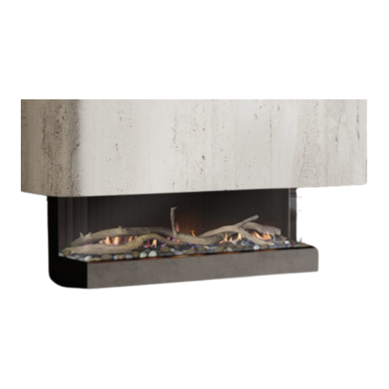
F L A M E E F F E C T G A S A P P L I A N C E
0 - 5 0 M F L U E C O N F I G U R A T I O N S
I N S T A L L A T I O N A N D O P E R A T I O N S M A N U A L
The Real Flame Nuvo Gas Appliance is designed to be installed into a frame out installation.
Designed to operate on Natural gas, LPG and ULPG
Approval no. GMK 10795
Consumer safety information: please read this manual before installing and operating this appliance.
Failure to follow these instructions may result in a possible fire hazard and/or injury and will void the
warranty.
Ve rsi on 2
N U V O 12 0 0 & 18 0 0

Advertisement

Table of Contents
loading
Need help?

Need help?

Do you have a question about the Nuvo 1200 and is the answer not in the manual?

Questions and answers

Subscribe to Our Youtube Channel

Summary of Contents for Real Flame Nuvo 1200

  • Page 1 I N S T A L L A T I O N A N D O P E R A T I O N S M A N U A L The Real Flame Nuvo Gas Appliance is designed to be installed into a frame out installation.
  • Page 2: Table Of Contents

    C O N T E N T S W ELCO ME SPECI FI CAT I ONS O P E R A T I O N I N S T R U C T I O N S USER I NSTR UC T IONS I N S T A L L A T I O N I N S T R U C T I O N S UNI T D I ME NS IONS MINI M UM FRA ME OUT DI ME NSI ON S...
  • Page 3: W Elco Me

    The Nuvo Range is simply breathtaking from all angles and configurations. Nuvo has been designed with fuel beds which have been crafted from bush gathered from the mountains surrounding Real Flame’s base in Melbourne, Victoria. We hope you create endless memories in front of this fireplace.
  • Page 4 I MP OR TANT SAFE T Y NOT ICE Do not place articles on or against this appliance. Do not use or store flammable materials in or near this appliance. Do not spray aerosols in the vicinity of this appliance whilst it is in operation. Care must be taken to ensure that any return air register or exhaust system does not adversely affect the operation of the appliance or draught of chimney or flue.
  • Page 5: Speci Fi Cat I Ons

    S P E C I F I C A T I O N S O F N U V O 12 0 0 Appliance Type Room Sealed Decorative Gas Fireplace Gas Type Natural Gas LPG ULPG Gas Input 27 High/21 Low 27 High/22 Low 21.5 High/18.5 Low Operating Pressure (TPP) 0.85kPa High /...
  • Page 6 S P E C I F I C A T I O N S O F N U V O 18 0 0 Appliance Type Room Sealed Decorative Gas Fireplace Gas Type Natural Gas ULPG Gas Input 35 High/29 Low 35 High/29 Low 28 High/23 Low Operating Pressure (TPP)
  • Page 7: O P E R A T I O N I N S T R U C T I O N S

    O P E R A T I O N I N S T R U C T I O N S Page...
  • Page 8: User I Nstr Uc T Ions

    U S E R I N S T R U C T I O N S C BUS or s im i la r co ntro l ( N o te req ui re s the • Do not operate if you smell gas. Turn appliance off, a p pl i an ce to b e co nnec ted to C BUS o r extinguish any open flame.
  • Page 9: I N S T A L L A T I O N I N S T R U C T I O N S

    I N S T A L L A T I O N I N S T R U C T I O N S Page...
  • Page 10: Uni T D I Me Ns Ions

    U N I T D I M E N S I O N S GAS INLET HOLE GAS INLET HOLE ELECTRICAL CONNECTIONS (REAR OF TRAY) UNIT NVS1200 1208 1040 1 140 NVS1800 1808 1040 314 1740 UNIT NVS1200 NVS1800 Page...
  • Page 11: Mini M Um Fra Me Out Di Me Nsi On S

    M I N I M U M F R A M E O U T D I M E N S I O N S S I N G L E S I D E D Gas supply hole N V S 12 0 0 N V S 18 0 0 Electrical cable hole 1050 1050...
  • Page 12 M I N I M U M F R A M E O U T D I M E N S I O N S S I N G L E S I D E D W I T H A P P L I A N C E 25mm min clearance to exhaust flue 435 min before...
  • Page 13 M I N I M U M F R A M E O U T D I M E N S I O N S T H R E E S I D E D Electrical Gas supply hole cable hole Note 617mm / 334mm / 90mm Allows for 10mm cladding to finish flush with appliance trims.
  • Page 14 M I N I M U M F R A M E O U T D I M E N S I O N S T H R E E S I D E D W I T H A P P L I A N C E 435 min 25mm min clearance to exhaust flue before...
  • Page 15 M I N I M U M F R A M E O U T D I M E N S I O N S T H R E E S I D E D W I T H F L A N G E K I T Gas supply hole Electrical cable hole Note 617mm / 334mm / 90mm...
  • Page 16 M I N I M U M F R A M E O U T D I M E N S I O N S T H R E E S I D E D W I T H A P P L I A N C E A N D F L A N G E K I T Wall shown 130mm thickness.
  • Page 17 T H R E E S I D E D W I T H A P P L I A N C E A N D F L A N G E K I T ( C O N T I N U E D . . ) 25mm min clearance to exhaust flue UN IT NV S 120 0...
  • Page 18 M I N I M U M F R A M E O U T D I M E N S I O N S H O R I Z O N T A L T E R M C L A D D I N G Opening- 300mm (w) X 460mm (h) 450mm MIN 260mm MIN...
  • Page 19 M I N I M U M F R A M E O U T D I M E N S I O N S V E R T I C A L T E R M I N S T A L L Decktite or lead collar flashing to suit 250mm flue diameter 435mm support spacing...
  • Page 20: F Ini S Hi N G O Pt Ion S

    F I N I S H I N G O P T I O N S F L U S H P L AST E R / M A R B L E E D G E P l a s t e r boa rd to be f inished with edge bead f or f l u s h f in i sh.
  • Page 21 F I N I S H I N G O P T I O N S E D G E F LAN GE P la s te r b oar d & othe r claddings to fi ni s h w i th f l ange kit B or d er ed ge f l a nge is fit ted to applianc e.
  • Page 22: In Stal L I Ng El Ec T Ric E Qu I Pm E Nt A Bove Fireplace

    I N S T A L L I N G E L E C T R O N I C E Q U I P M E N T A B O V E Y O U R F I R E P L A C E *Electronics can be installed in this Zone.
  • Page 23: In Stal L Ati O N I Nstr Uc T Ion S

    I N S T A L L A T I O N I N S T R U C T I O N S LO C AT IO N Do not exceed maximum rated pressures. Select a location where the fire can be supervised during operation.
  • Page 24: In Stal L Er I Nsta Ll At Ion St E P List

    I N S T A L L E R I N S T A L L A T I O N S T E P L I S T 1. Install appliance, ensure clearances to combustibles are met. Ensure top is supported by hanging brackets or by timber / steel beams.
  • Page 25: In Stal L Ati O N Acc E Ss Pa N E L

    I N S T A L L A T I O N A C C E S S P A N E L The lower front panel may be removed to enable a quick installation. Removal of panel will allow easy access to gas connection.
  • Page 26: In Stal L Ati O N Re St Ric T Ion S

    I N S T A L L A T I O N R E S T R I C T I O N S No Plaster / fascia screws to be fitted in the shaded areas. Failure may result in damaged glass or inability to remove componentry.
  • Page 27: Top Sta N Do F F F It Me Nt

    F R O N T T R A N S I T S U P P O R T For transit and correct mounting the appliance is fitted with Support Bracket Fitted / Removed support brackets. Once appliance is installed into location. The appliance top must be supported via either hanging from the top standoff brackets or by attaching the top support bracket to support beams.
  • Page 28: Exte R N Al Wall Moun Te D Fa N Module Installat Ion

    E X T E R N A L W A L L M O U N T E D F A N M O D U L E I N S T A L L A T I O N 1.
  • Page 29 Repeat above with air intake flue pipe to heater Cut tube to length where connection. Both Flues must touch firmly down before the required. clamps are tightened. Ensure ends are burr free Clip flues as required to provide adequate support. 6. and round, test fit flue will Connection to wall mounted fan terminal.
  • Page 30 Proceed termination into cavity. Fit flue clamp over flue Ensure the termination is (loosely) and attach to verticle and is not leaning the exhaust end of the backwards termination and tighten the clamp. If there is no access to the termination from inside,fit flues prior...
  • Page 31 Set fan speed according to the flue length. Refer to Appendix 3. Fit front cover. Page...
  • Page 32: Roof To P Te Rmi Nati On Wi Th E Xt Ernal M Otor

    R O O F T O P T E R M I N A T I O N W I T H E X T E R N A L M O T O R Se t u p w it h ext ernal ro of top ter min a tion Maximum 50m flue length 460.0 Ro o f to p t erm i nat i on...
  • Page 33 Apply an 8mm silicon bead fully around the inside of the flue end (heater connection end) Fit flue clamp over flue (loosely). Remove the screws from the top plate of the term and proceed to remove the top plate. Slide flue onto connection spigot fully.
  • Page 34 Fit flue clamp over flue (loosely) and attach to Fit a decktite (50-300mm) the exhaust end of the or similar sealant to close termination and tighten the gap between the the clamp. Make sure you roof and termination as push the exhaust flue fully manufacturer’s to the termination socket recommendation.
  • Page 35 Attach screws to the side mount. Pull the cable to the top of the termination and attach to the connection block as shown below. Please ensure that the leads do not touch the motor in any way (cable tie if necessary).
  • Page 36: F It Ti Ng S I D E Pa Ne Ls

    F I T T I N G S I D E P A N E L S The Nuvo fireplace can be configured to a 1 sided setting, RH corner setting, LH corner setting or a 3 sided viewing configuration. Slide the outer side panel The unit is supplied as standard in a 3 sided configuration upwards and into the...
  • Page 37: F It Ti Ng Lowe R F Ront T Ri M

    F I T T I N G L O W E R F R O N T T R I M The middle trim between Fit the front trim and screw the front trim and the 7 screws into place by fireplace should easily...
  • Page 38: Com M I Ss I O Ni Ng Pr Oce Dure

    C O M M I S S I O N I N G P R O C E D U R E O n c e t he f ire is i nst a ll ed : 1. Install media. 2.
  • Page 39: Med I A I Nsta Llat Ion

    M E D I A I N S T A L L A T I O N G E N ER AL I NSTAL L ATIO N NOT E Lay media as per instructions along the entire length of the burner. Refer specific instructions below for each media type. Media where across the burner should be laid in a criss cross pattern along the full length of the burner.
  • Page 40 N ordic Pi ne Ar rang em e nt In st ruc t io n Media must be laid out from corner to corner of the Spread coals randomly on and along the burner, avoid firebox. Start media placement from a corner by placing blocking the burner channel and the air grate.
  • Page 41 Do not over stack (triple stack logs). Scan to view the instructions video. Page...
  • Page 42 Redgum w ith ass o r te d co als A rran ge m en t Ins tr uct i on Media must be laid out from corner to corner of the Spread coals randomly on and along the burner, avoid firebox.
  • Page 43 Al pi n e Fores t Ar rang em e nt In st ruc t io n • Lay coals media in a random arrangement along the Start by placing the coals first and make sure you do not entire length of the burner. block the burner channel or the air grate at the back.
  • Page 44 Make sure the burner channel is not smothered and there is no media on the air intake grate. After the coals and bark chips have been spread evenly, proceed to placing logs on the media bed. Make sure the below steps are followed for an even flame pattern NOT E- Log setup for NVS1800 (step 5) differs and look of the fireplace.
  • Page 45 Riv e r Gorg e Ar rang em e nt In st ruc t io n • Lay pebbles media in a random arrangement along Start by placing the pebbles first and make sure you do the entire length of the burner. not block the burner channel or the air grate at the back.
  • Page 46 N OT E - Step 4 is only for the NVS1800 arrangement. The log segments can be connected in four different orientations - only one is correct. To ensure that the segments are oriented correctly, match the bark detail at the connection points.
  • Page 47 Tasma n S horel ine Ar rang em e nt In st ruc t io n • Lay mixed pebbles media in a random arrangement Start by placing the pebbles first and make sure you do along the entire length of the burner. not block the burner channel or the air grate at the back.
  • Page 48 NOTE - Centre of the assembled log must rest on the pilot bracket and the two ends must not end up on the burner channel. The log segments can be connected in four different orientations - only one is correct. To ensure that the segments are oriented correctly, match the bark detail at the connection points.
  • Page 49: Con Ver Si O N De Tai Ls

    C O N V E R S I O N D E T A I L S / I N J E C T O R – P I L O T A N D B U R N E R R E M O V A L N at u ra l ga s / P rop a ne /UL PG Fit suction cups on the glass and lift glass up and hinge out...
  • Page 50 Detach the burner and placed flat to store until refitting. The media can be repainted using an approved high temperature paint, contact Real Flame for details. Turn burner over gently. AVOIDING DAMAGING THE INSULATION Loosen gas pipe nuts form injectors and move gas pipe away.
  • Page 51 Using a 15mm and 16mm spanner remove injector shaft Using a 15mm and 16mm spanner undo the bottom nut Replace with new injector shaft and olive. Undo grub screw (Allen key 2.5mm AF ). Injector assembly Ensure that the shaft fits at the base of the elbow can now be removed.
  • Page 52 PILOT RE-FITMENT Ensure there are no gaps between injector nut and cap. Proceed to fit the grub screw with 2.5mm allen key. Replace pilot orifice with correct gas type. Refit pilot gas pipe and tighten Refit spark probe and gently tightly Refit spark lead Push pilot assembly down to original position and refit the bracket retaining screw.
  • Page 53 BURNER RE-FITMENT Check appliance for correct flame operation, Check pilot flame, Check main burner is not smothered and flames are even along burner with correct colour Carefully place burner into firebox, supporting LH end of and not excessively yellow or sooty. (Note it takes upto the burner.
  • Page 54: Par Ts L I St

    P A R T S L I S T Pa r ts P i c t u re Valve SIT Pilot assembly- refer gas type Injector Natural gas- refer gas type Techrite Ignition System Page...
  • Page 55: App E Nd I X 1- F Lu E T E Rmin At Ion

    A P P E N D I X 1 - F L U E T E R M I N A T I O N Page...
  • Page 56: App E Nd I X 2- Wiri Ng Diag Ra M S

    A P P E N D I X 2 - W I R I N G D I A G R A M S Techr ite Ig nit ion Pa ck CBUS Wiring Page...
  • Page 57: App E Nd I X 3- Se T T In G F L Ue Fa N Speed

    A P P E N D I X 3 - S E T T I N G F L U E F A N S P E E D The powerflue fan has an adjustable speed control. The speed should be set to match the appliance and the flue length.
  • Page 58: War R An T Y I Nf Ormat I On

    Pty Ltd and in New Zealand by Glen Dimplex New Zealand Ltd (together referred as “Glen Dimplex”) This warranty is provided Supplier Name___________________________________ to the first domestic purchaser of a Real Flame gas appliance. Date Of Purchase / settlement of property if new home 1. Warra n t y...
  • Page 59 Website: Telephone: www.realflame.com.au AU: 1300 554 155 www.realflame.co.nz NZ: +64 9 274 8265 Glen Dimplex. All rights reserved. Material contained in this publication may not be reproduced in whole or in part, without prior permission in writing from Glen Dimplex.

This manual is also suitable for:

Nuvo 1800

Table of Contents