Table of Contents
Advertisement
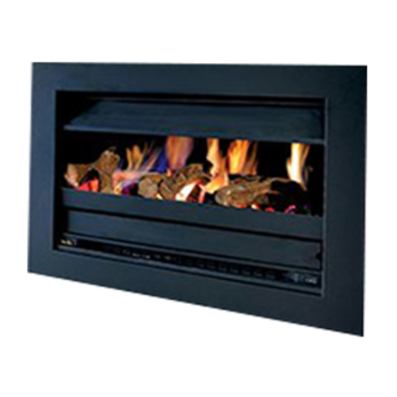
HEATSEEKER
®
GAS FIREBOX
INSTALLATION & OPERATING MANUAL
The Heatseeker Gas Firebox is approved to be installed into a masonary
fireplace and as a zero clearance firebox and is designed to operate on
Natural Gas and Propane (LPG) gases ONLY. Approval Number GMK10100.
Installed primarily as a decorative appliance. Not certified as a Space Heater.
VERSION 35
Advertisement
Table of Contents

Related Manuals for Real Flame Heatseeker Series


Summary of Contents for Real Flame Heatseeker Series
- Page 1 HEATSEEKER ® GAS FIREBOX INSTALLATION & OPERATING MANUAL The Heatseeker Gas Firebox is approved to be installed into a masonary fireplace and as a zero clearance firebox and is designed to operate on Natural Gas and Propane (LPG) gases ONLY. Approval Number GMK10100. Installed primarily as a decorative appliance.
- Page 2 Date Of Purchase / settlement of property if new home _________________ Model / Serial Number_______________________ This warranty does not cover the cost of claiming under the warranty or transporting the Real Flame Gas Burner to and from the supplier. Our goods come with guarantees that cannot be excluded under the Australian Consumer Law. You are entitled to a replacement or refund for a major failure and for compensation for any other reasonably foreseeable loss or damage.
- Page 3 INSTALLATION NOTICE The installation of this appliance is only to be carried out by an authorised person in accordance with the Manufacturer’s Instructions, local gas fitting regulations, AS/NZS5601.1-2013 installation code for gas burning appliances and any other relevant statutory regulations. In all cases the installation of this appliance shall meet the requirements as set out in AS/NZS5601.1-2013.
-
Page 4: Table Of Contents
Internal Motor ..................40 External Motor ..................41 Dimensions....................42 Troubleshooting Electronic Ignition and Power Flue System ....43 Wiring Diagram..................45 Parts kit .......................46 Flue termination (cowls) regulations ..............47 Marble trim installation instructions...............48 Mantlepiece installation instructions ..............49 Electrical diagram ....................50 Real Flame contact information ................52... -
Page 5: Data Plate
(Affixed to burner) DATA PLATE HSIB600 Fitted with Magiglo 400 or 400EI burner Injector Size (mm) N.G.C. (Mj/Hr) Natural Gas 1 x 2.60 0.80 kPa ULPG 1 x 1.30 2.70 kPa Fitted with Magiglo 540 or 540EI burner Injector Size (mm) N.G.C. -
Page 6: Parts & Pressure Checks
PARTS Rear Log Fixing Hole Burner Port Pilot Assembly Fixing Bracket Pilot Cover Plate Gas Connection Detachable Skirt Burner Pressure Test Point Maximum Pressure Setting Screw Minimum Pressure Setting Pilot Pressure Adjustment TO CHECK PRESSURES 1. Fit manometer to test point. 2. -
Page 7: Inbuilt Model Installation Diagrams
HEATSEEKER INBUILT MODEL • Unit installed into an existing “working” fireplace requires an AGA approved 225mm gas cowl and chimney plate fixed to the chimney top. • If the fireplace is not a “working” fireplace, then the applicable flue to the model being installed should be installed using a gather, single skin flue and AGA approved gas cowl. -
Page 8: Dimensions Heatseeker 600
DIMENSIONS Heatseeker 600 Heatseeker 600 Trim FRONT - 4 SIDED FRONT - 3 SIDED... -
Page 9: Dimensions Heatseeker 850
DIMENSIONS Heatseeker 850 Heatseeker 850 Trim FRONT - 4 SIDED FRONT - 3 SIDED 1040... -
Page 10: Dimensions Heatseeker 1000
DIMENSIONS Heatseeker 1000 1130 1005 Heatseeker 1000 Trim FRONT - 4 SIDED FRONT - 3 SIDED 1190 1140... -
Page 11: Dimensions Heatseeker 600 Zc
DIMENSIONS Heatseeker 600 ZC Heatseeker 600 ZC Trim FRONT - 4 SIDED FRONT - 3 SIDED... -
Page 12: Dimensions Heatseeker 850 Zc
DIMENSIONS Heatseeker 850 ZC Heatseeker 850 ZC Trim FRONT - 4 SIDED FRONT - 3 SIDED 1040... -
Page 13: Dimensions Heatseeker 1000 Zc
DIMENSIONS Heatseeker 1000 ZC 1130 1075 Heatseeker 1000 ZC Trim FRONT - 4 SIDED FRONT - 3 SIDED 1190 1140... -
Page 14: Inbuilt Installation Procedure
Connect to gas supply using 15mm copper union Connect to power supply Assemble log and coal or pebble set as shown (Figures 1-7). IMPORT NT! Only logs, coals and pebbles supplied by Real Flame are to be used. Figure (1) Remove box containing logset, and Figure (2) Place the 14 large coals and 8 small coals unpack. - Page 15 Heatseeker Inbuilt Installation Procedure The Heatseeker Gas Firebox (Natural Gas Only) is approved for use with Pebbles. To install the Pebbles, follow the installation instructions as per Figures 5-7. Note: A Real Flame Pebble Tray needs to be ordered for this option.
- Page 16 HEATSEEKER INBUILT MODEL Redgum Log Media Recommended Set Up 400 Burner STEP 1. Place coals on top of the burner. (Maximum 4 coals on burner channel.) STEP 2. Place underlying layer of logs. STEP 3. Place top layer of logs. Note: Do not overcrowd burner channel - Maximum 4 coals on burner channel.
- Page 17 HEATSEEKER INBUILT MODEL Redgum Log Media Recommended Set Up 540 Burner STEP 1. Place coals on top of the burner. (Maximum 6 coals on burner channel.) STEP 2. Place underlying layer of logs. STEP 3. Place top layer of logs. Note: Do not overcrowd burner channel - Maximum 6 coals on burner channel.
- Page 18 HEATSEEKER INBUILT MODEL Redgum Log Media Recommended Set Up 750 Burner STEP 1. Place coals on top of the burner. (Maximum 9 coals on burner channel.) STEP 2. Place underlying layer of logs. STEP 3. Place top layer of logs. Note: Do not overcrowd burner channel - Maximum 9 coals on burner channel.
- Page 19 HEATSEEKER INBUILT MODEL Forrest Log Media Recommended Set Up 400 Burner STEP 1. Place coals on top of the burner. (Maximum 4 coals on burner channel.) STEP 2. Place underlying layer of logs. STEP 3. Place top layer of logs. Note: Do not overcrowd burner channel - Maximum 4 coals on burner channel.
- Page 20 HEATSEEKER INBUILT MODEL Forrest Log Media Recommended Set Up 540 Burner STEP 1. Place coals on top of the burner. (Maximum 6 coals on burner channel.) STEP 2. Place underlying layer of logs. STEP 3. Place top layer of logs. Note: Do not overcrowd burner channel - Maximum 6 coals on burner channel.
- Page 21 HEATSEEKER INBUILT MODEL Redgum Log Media Recommended Set Up 750 Burner STEP 1. Place coals on top of the burner. (Maximum 9 coals on burner channel.) STEP 2. Place underlying layer of logs. STEP 3. Place top layer of logs. Note: Do not overcrowd burner channel - Maximum 9 coals on burner channel.
- Page 22 TICK BOXES Fit the trim to the front of the firebox. Light the unit following the procedure on page 27. Install the 225mm AGA approved gas cowl where using the chimney to vent the fumes. Test the unit for safe operation and show customer correct operating procedures. Test for spillage.
-
Page 23: Zero Clearance Timber Frame Installation
HEATSEEKER ZERO CLEARANCE MODEL Heatseeker Zero Clearance Timber Frame Installation (Recommended only) (Recommended only) IMPORT NT Install unit and fluing before plasterboard. Plaster to run beyond stud and HEATER behind trim From hearth TRIM Approx 20mm for hearth if required. Frameout Dimensions (in mm) NOTE: If fire is to be installed off the floor with a 4 sided MODEL... -
Page 24: Zero Clearance Model Components
HEATSEEKER ZERO CLEARANCE MODEL Position the Heatseeker firebox in the selected installation position in the room. You will require the Zero Clearance Kit to suit the Heatseeker model you are fitting. This should be fitted to the firebox as shown on page 25. Components ZERO CLE R NCE KIT COMPONENTS No. -
Page 25: Zero Clearance Model Assembly
HEATSEEKER ZERO CLEARANCE MODEL Fit Zero Clearance Kit to unit as shown below: ITEM 8 ITEM 7 ITEM 7 ITEM 6 ITEM 1 Place main fire box (Item 1) Secure side strips (Item 7) and Secure gather centrally on base panel and top strip (Item 8) to main fire (Item 6) to main secure. -
Page 26: Zero Clearance Model Installation Procedure
HEATSEEKER ZERO CLEARANCE MODEL Heatseeker Zero Clearance Installation Procedure TICK BOXES Connect to gas supply Connect to power supply Install flue to 600mm minimum above roof line. (Min. total flue run 3.6m) Plaster to unit with trim removed Install trim Assemble unit as per page 19 Test the unit for safe operation and show customer correct operating procedures. -
Page 27: Lighting Instructions
LIGHTING PILOT AND MAIN BURNER Before lighting the pilot make sure that the gas line is connected. FOR YOUR SAFETY READ BEFORE LIGHTING The appliance has a pilot which must be lit using the piezo ignition, when lighting the pilot follow the instructions exactly. -
Page 28: Commissioning
LIGHTING INSTRUCTIONS - Millivolt Option Visit www.realflame.com.au STOP! Read the safety information. to view a video instruction. Push in gas control knob and turn to “PILOT” NOTE: Control knob cannot be turned from “OFF” to “PILOT” unless the knob is pushed in slightly. -
Page 29: Optional Safety Screen
OPTIONAL SAFETY SCREEN An optional safety screen can be fitted to Heatseeker units The safety screens are provided with magnetic catches located at the handle and the holding bracket to hold the screen in the open and closed position respectively. Installation Method Fit the 18 mm magnets on to the screen. - Page 30 (continued) OPTIONAL SAFETY SCREEN Drill the holes (5 off) onto the top baffle of the combustion chamber using the holding bracket as a guidance. Assemble the safety screen with the holding bracket. a. Screw the screen onto the holding bracket inserts. b.
- Page 31 (continued) OPTIONAL SAFETY SCREEN Fit the holding bracket/ screen assembly onto the top baffle of the combustion chamber. a. Use 4mm X10 Aluminum pop rivets (5 off). b. Make sure the screen is moving freely upwards and downwards c. Make sure locking mechanism holds the screen in the open position. Locate the screen in the closed position.
-
Page 32: Flue Requirements
FLUE REQUIREMENTS Natural Draught The standard natural draught flue kit consists of 4 x 900mm lengths of twin skin flue (refer to page 23 for correct sizing) and an AGA approved cowl. 200mm 2 lengths above 500mm last bend 200mm Max. -
Page 33: Optional Power Flue
FLUE REQUIREMENTS Power Flue Kit (Optional – refer to pages 30 to 42 for details) The standard Power Flue Kit consists of ; • 1 x Power Flue Fan • 1 x Power Flue Motor • 1 x Control Module •... -
Page 34: Introduction
F N F ILURE SENSING DEVICE All Real Flame Power Flue systems are fitted with a sensing device within the unit to ensure that, in the event of flow failure, the safety shut off valve within the module will go into lockout and shut off the gas supply to the unit. - Page 35 (continued) INSTALLATION INSTRUCTIONS LOC TION OF FLUE TERMIN L FOR POWER FLUE Listed below are the minimum clearances required for fan-assisted terminations: Below eaves, balconies and other projections............200mm Below eaves, balconies and other projections for a 1500 & 1800 model ....300mm From the ground, above a balcony or other surface..........300mm From a return wall or external corner.................300mm From a Gas meter....................1000mm...
- Page 36 SERVICING OF THE POWER FLUE MOTOR The Real Flame Power Flue motor is designed so as to make servicing the motor a simple task. The power lead connected to the motor is to be disconnected (unplugged) and the screws are to be undone, the fan motor will then lift out for servicing.
-
Page 37: Commissioning
COMMISSIONING THE POWER FLUE SYSTEM THE INSTALLER MUST COMMISSION THE POWERFLUE SYSTEM AS PER CLAUSE H2.2.7 (AS5601.1.2013) The correct CO concentration shall be established by adjustment of dampers and checked by flue gas analysis. A check that the controls are operating in the manner specified shall be carried out. The check shall include a simulation of fan failure. -
Page 38: Motor Clearance
POWER FLUE MOTOR CLEARANCE Minimum clearance 250mm Ensure there is adequate ventilation within this cavity to prevent motor over- 150mm/200mm heating. twin skin flue - optional for additional height Baffle Height 980mm and diameter 350mm... -
Page 39: Frameout
TYPICAL POWER FLUE FRAMEOUT Pressure Motor Differential Switch Motor Fan Casing... -
Page 40: Internal Motor
INTERNAL MOTOR 500mm Top Termination 250mm min. 150mm x 200mm or 200/250mm Access 200mm or 300mm flue extension Panel Flush Cowl Min. Distance Motor termination Domestic: 220mm twin skin flue (if required) Baffle 900mm Heater 25mm Flue Minimum 25mm clearance from outer flue to combustible interior. - Page 41 DIMENSIONS External Flue Motor 55/5 90/40 20 200/250 150/200 MODELS H mm G mm Double Vision, Hot Box and all Heatseekers Pure Vision, Simplicity, Elegance, Signature, Hybrid 850, 1000 & 1500 Sizes Pure Vision, Simplicity, Elegance, Signature, Hybrid 1800 & 3300 Sizes Power Flue Flush Power Flue Flush Termination 500 x 500...
-
Page 42: Dimensions
DIMENSIONS Internal Power Flue Motor Internal Power Flue Motor 200/250... -
Page 43: Troubleshooting Electronic Ignition And Power Flue System
TROUBLE SHOOTING FOR ELECTRONIC IGNITION AND POWER FLUE SYSTEM. Symptom Possible Cause Corrective Action Fire turned on and No Power to Module Connect Power nothing happens Fire turned on and Pressure switch not Check pressure switch motor starts but operating there is no spark Fire sparks when A. - Page 44 TROUBLE SHOOTING FOR ELECTRONIC IGNITION AND (continued) POWER FLUE SYSTEM. The power flue and electronic control box have a red LED light that indicates the possible cause of a problem, the LED light will flash in different sequences for different problems, the most common are:- Long Flash Short Flash...
-
Page 45: Wiring Diagram
POWER FLUE WIRING DIAGRAM TECHRITE POWER FLUE CONTROL MODULE Sparker Heat Sensor LED Indicator Pressure Power Switch Double Block Solenoid NOTE For C Bus and/or fresh air damper interlock systems, please contact us for wiring diagrams and relevant system instructions at info@realflame.com.au... -
Page 46: Parts Kit
PARTS LIST PART No. DESCRIPTION PART No. Eurosit 630 Valve 1/2˝ to 3/8˝ Hex Nipple Regulator SC-75 5/16˝ 90O Union Elbow 1/4˝ Nut and Olive S.I.T. ODS Pilot Assembly (Natural Gas) Injector Holder Stem S.I.T. ODS Pilot Assembly (Propane Gas) Injector 1/2˝... -
Page 47: Flue Termination (Cowls) Regulations
HEATSEEKER FLUE TERMINATION (COWLS) REGULATIONS Natural Draught Refer to Note 1 Refer to Note 1 A OR B 600mm AREA CLEARANCE REQUIRED Horizontally from a neighboring structure............1000mm If less than a meter horizontally from a neighboring structure then terminates above that structure by............500mm From any opening into a building. -
Page 48: Marble Trim Installation Instructions
(Not supplied by Real Flame.) OPTIONAL MARBLE HEARTH AND/OR MARGIN SET 1190mm 275mm 620mm 270mm 375mm 1810mm Marble Margin Set Installation Procedure Install Heatseeker with trim in place. Install marble over trim up to the fire opening. Use liquid nails to fix to wall. Marble should look like the diagram below once it has been installed and before mantelpiece has been attached. -
Page 49: Mantlepiece Installation Instructions
(Not supplied by Real Flame.) OPTIONAL MANTELPIECE INSTALLATION Wall Stud Firebox Trim Marble Margin Mantel Leg Mantel Shelf (Internal (Internal Dimension) Dimension) M NTELPIECE DIMENSIONS Federation Square 1440 1340 1165 Adelaide Federation 1460 1300 1170 Windsor Universal 1810 1665 1180... -
Page 50: Electrical Diagram
ELECTRICAL DIAGRAM Electrical Ignition models TECHRITE IGNITION PACK TAIS-CP-R15-D5-000V SPARK ON/OFF SWITCH BROWN GREEN/YELLOW BLUE BLUE BROWN BROWN FUSE FAN SWITCH FLAME SENSING BLUE BLUE BROWN BROWN (HIGH) NOT USED WHITE WHITE (LOW) VALVE BLACK (MED) BLACK BLUE BLUE GREEN/YELLOW Powerflue models TECHRITE IGNITION PACK TAIS-CP-R15-D5-000V... -
Page 52: Real Flame Contact Information
GLEN DIMPLEX AUSTRALIA PTY LTD ABN 69 118 275 460 Head Office/Factory/Showroom 1340 Ferntree Gully Rd. Scoresby Vic 3179 Ph: (03) 8706 2000 Fax: (03) 8706 2001 E-mail: info@realflame.com.au Richmond - VIC Showroom 300 Swan St. Richmond Vic 3121 Ph: (03) 9428 4443 Fax: (03) 9428 4445 Dandenong - VIC Showroom 3/328 South Gippsland Highway, Dandenong South Vic 3164...
Need help?
Do you have a question about the Heatseeker Series and is the answer not in the manual?
Questions and answers