Table of Contents
Advertisement
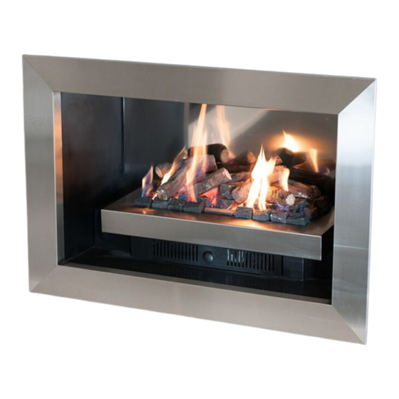
ELEGANCE
®
DECORATIVE FIREBOX
INSTALLATION & OPERATING MANUAL
Elegance fire boxes are approved to be installed as a zero clearance firebox
and are designed to operate on Natural Gas and ULPG gases ONLY.
Approval Number: GMK10099
Installed primarily as a decorative appliance. Not certified as a Space Heater.
VERSION 10
Advertisement
Table of Contents

Related Manuals for Real Flame Elegance Series


Summary of Contents for Real Flame Elegance Series
- Page 1 ELEGANCE ® DECORATIVE FIREBOX INSTALLATION & OPERATING MANUAL Elegance fire boxes are approved to be installed as a zero clearance firebox and are designed to operate on Natural Gas and ULPG gases ONLY. Approval Number: GMK10099 Installed primarily as a decorative appliance. Not certified as a Space Heater. VERSION 10...
- Page 2 WARRANTY INFORMATION The benefits provided to you under the following warranty are in addition to any other rights and remedies available to you under the law. 1. Warranty during the first 15 years from the date of purchase (Firebox Warranty Period), there is a defect in the firebox of the Gas Burner;...
- Page 3 INSTALLATION NOTICE The installation of this appliance is only to be carried out by an authorised person in accordance with the Manufacturer’s Instructions, local gas fitting regulations, AS/NZS 5601.1-2013 installation code for gas burning appliances and any other relevant statutory regulations. In all cases the installation of this appliance shall meet the requirements as set out in AS/NZS 5601.1-2013.
-
Page 4: Table Of Contents
CONTENTS Contents .........................4 Data Plate .......................5 Zero Clearance Modular Installation & Dimensions..........6 Dimensions Elegance 1000 ..................7 Dimensions Elegance 1500 ..................8 Dimensions Elegance 1800 ..................9 Dimensions Elegance 3300 ..................10 Zero Clearance Modular Installation Timber Frame Installation ..............11 Installation Check List................12 Lighting/Testing and Failure Procedure ..............13 Flue Requirements (Standard) ................14 Flue Requirements (Power Flue Kit)..............15 Optional Power Flue .....................16... -
Page 5: Data Plate
(Affixed to the base of the unit for reference to gas pressure & consumption) DATA PLATE Elegance 1000 & Elegance Signature 1000 Fitted with Magiglo 750 or 750EI burner Injector Size (mm) N.G.C. (Mj/Hr) Natural Gas 3 x 1.90 0.75 kPa ULPG 3 x 0.95 2.55 kPa... -
Page 6: Zero Clearance Modular Installation & Dimensions
ZERO CLEARANCE MODULAR INSTALLATION • The Firebox is designed to be installed into a new frame out as shown on page 11. • The fire can be installed at ground level or raised to what ever height is required providing the flue length is 2.7 meters or more. -
Page 7: Dimensions Elegance 1000
DIMENSIONS Elegance 1000 1100 Elegance 1000 Trim FRONT - 4 SIDED FRONT - 3 SIDED 1193 1193... -
Page 8: Dimensions Elegance 1500
DIMENSIONS 1000 1600 Elegance 1500 Elegance 1500 Trim FRONT - 4 SIDED FRONT - 3 SIDED 1690 1690... -
Page 9: Dimensions Elegance 1800
1135 1900 DIMENSIONS Elegance 1800 Elegance 1800 Trim FRONT - 4 SIDED FRONT - 3 SIDED 1990 1990... -
Page 10: Dimensions Elegance 3300
DIMENSIONS Elegance 3300 1135 3400... -
Page 11: Timber Frame Installation
ZERO CLEARANCE MODULAR INSTALLATION Timber Frame Installation (Recommended only) IMPORT NT Install unit and fluing before plasterboard. NOTE: All Modular fires and flue kits are to be installed PRIOR to plasterboard. Plasterboard is to be run past stud frame and up to fire opening either terminating in square edge, or for Elegance a 3 or 4 sided trim finish. -
Page 12: Installation Check List
ZERO CLEARANCE MODULAR INSTALLATION Installation Procedure TICK BOXES Check frame out has been constructed correctly and has not been plastered. Check frame out and structure above is clear of any structures that may impede the flue run. If the flue needs to be off set with 45 deg bends, the offset length can be no more than 20% of the total flue run. -
Page 13: Lighting/Testing And Failure Procedure
LIGHTING MAIN BURNER FOR YOUR SAFETY READ BEFORE LIGHTING Before igniting the fire, check for gas leaks. Use only the ignition components supplied. Do not use this appliance if any part has been under water. Immediately call a qualified service technician to inspect the appliance and replace any part of the control system and any gas control that has been under water. -
Page 14: Flue Requirements (Standard)
FLUE REQUIREMENTS Natural Draught The standard natural draught flue kit consists of 4 x 900mm lengths of twin skin flue (refer to page 5 for correct sizing) and an AGA approved cowl. 200mm 2 lengths above 500mm last bend 200mm Max. -
Page 15: Flue Requirements (Power Flue Kit)
FLUE REQUIREMENTS Power Flue Kit (Optional – refer to pages 15 to 27 for details) The standard Power Flue Kit consists of ; • 1 x Power Flue Fan • 1 x Power Flue Motor • 1 x Control Module •... -
Page 16: Optional Power Flue
INTRODUCTION - THE POWER FLUE SYSTEM POWER FLUE DESIGN A ‘flue’ using a fan to remove or assist in removing combustion products from an appliance, is known as a ‘power flue’. A power flue application can be used to enable a client to have a decorative fire with a horizontal flue run or a vertical flue run where flue space is inadequate for the normal flue. - Page 17 (continued) INSTALLATION INSTRUCTIONS LOC TION OF FLUE TERMIN L FOR POWER FLUE Listed below are the minimum clearances required for fan-assisted terminations: Below eaves, balconies and other projections............200mm Below eaves, balconies and other projections for a 1500 & 1800 model ....300mm From the ground, above a balcony or other surface..........300mm From a return wall or external corner.................300mm From a Gas meter....................1000mm...
- Page 18 (continued) INSTALLATION INSTRUCTIONS FLUE SIZE The flue size for each model is different. Please refer to the table below. MODELS A mm B mm Double Vision, Hot Box and all Heatseekers Pure Vision, Simplicity, Elegance, Signature, Hybrid 1000 & 1500 Sizes Pure Vision, Simplicity, Elegance, Signature, Hybrid 1800 &...
-
Page 19: Commissioning
COMMISSIONING THE POWER FLUE SYSTEM THE INSTALLER MUST COMMISSION THE POWERFLUE SYSTEM AS PER CLAUSE H2.2.7 (AS5601.1.2013) The correct CO concentration shall be established by adjustment of dampers and checked by flue gas analysis. A check that the controls are operating in the manner specified shall be carried out. The check shall include a simulation of fan failure. -
Page 20: Motor Clearance
POWER FLUE MOTOR CLEARANCE Minimum clearance 250mm Ensure there is adequate ventilation within this cavity to prevent motor over- or 200mm/250mm 150mm/200mm heating. twin skin flue - optional for additional height Baffle Height 980mm and diameter 350mm... -
Page 21: Frameout
TYPICAL POWER FLUE FRAMEOUT Pressure Motor Differential Switch Motor Fan Casing... -
Page 22: Internal Motor
INTERNAL MOTOR 500mm Top Termination 250mm min. 150mm x 200mm or 200/250mm Access 200mm or 300mm flue extension Panel Flush Cowl Min. Distance Motor termination Domestic: 220mm twin skin flue (if required) Baffle 900mm Heater 25mm Flue Minimum 25mm clearance from outer flue to combustible interior. -
Page 23: Dimensions
DIMENSIONS External Flue Motor 55/5 90/40 20 200/250 150/200 MODELS H mm G mm Double Vision, Hot Box and all Heatseekers Pure Vision, Simplicity, Elegance, Signature, Hybrid 1000 & 1500 Sizes Pure Vision, Simplicity, Elegance, Signature, Hybrid 1800 & 3300 Sizes Power Flue Flush Power Flue Flush Termination 500 x 500... - Page 24 DIMENSIONS Internal Power Flue Motor Internal Power Flue Motor 200/250...
-
Page 25: Troubleshooting Electronic Ignition And Power Flue System
TROUBLE SHOOTING FOR ELECTRONIC IGNITION AND POWER FLUE SYSTEM. Symptom Possible Cause Corrective Action Fire turned on and No Power to Module Connect Power nothing happens Fire turned on and Pressure switch not Check pressure switch motor starts but operating there is no spark Fire sparks when A. - Page 26 TROUBLE SHOOTING FOR ELECTRONIC IGNITION AND (continued) POWER FLUE SYSTEM. The power flue and electronic control box have a red LED light that indicates the possible cause of a problem, the LED light will flash in different sequences for different problems, the most common are:- Long Flash Short Flash...
-
Page 27: Wiring Diagram
POWER FLUE WIRING DIAGRAM TECHRITE POWER FLUE CONTROL MODULE Sparker Heat Sensor LED Indicator Pressure Power Switch Double Block Solenoid NOTE For C Bus and/or fresh air damper interlock systems, please contact us for wiring diagrams and relevant system instructions at info@realflame.com.au... -
Page 28: Parts
White Rogers Valve Used For Dungs Valve used On 1400 Sparker and Sensor Fitted to all Electronic Ignition For 850 & 100 Burner In 1800 Modular Box. Electronic Ignitions. Modular Boxes. Part Number: DUBM 241221 Part Number: GST0829985 Part Number: W0079 Techrite Electronic Ignition Techrite Power Flue Module used Regulator fitted to all Natural Gas... -
Page 29: Trims
TRIMS MODEL ELEGANCE 850 1043 1043 ELEGANCE 1000 1193 1193 ELEGANCE 1500 1693 1693 ELEGANCE 1800 1990 1990... -
Page 32: Glen Dimplex Contact Information
GLEN DIMPLEX AUSTRALIA PTY LTD ABN 69 118 275 460 Head Office/Factory/Showroom 1340 Ferntree Gully Rd. Scoresby Vic 3179 Ph: (03) 8706 2000 Fax: (03) 8706 2001 E-mail: info@realflame.com.au Richmond - VIC Showroom 300 Swan St. Richmond Vic 3121 Ph: (03) 9428 4443 Fax: (03) 9428 4445 Dandenong - VIC Showroom 3/328 South Gippsland Highway, Dandenong South Vic 3164...
Need help?
Do you have a question about the Elegance Series and is the answer not in the manual?
Questions and answers