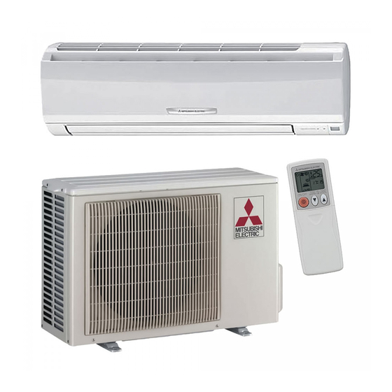
Mitsubishi Electric M Series Manual
Hide thumbs Also See for M Series:

Advertisement

M-SERIES
Accessories
1. CONTROLS ....................................................................................................................................................................... 2
1-1. System Control.......................................................................................................................................................... 3
1-2. Wired Remote Controller [PAR-32MAA-J] ................................................................................................................ 6
1-3. Simple MA Remote Controller [PAC-YT53CRAU] ................................................................................................... 26
1-4. System Control Interface [MAC-333IF-E]................................................................................................................ 48
1-5. Wireless Adapter [PAC-WHS01WF-E] .................................................................................................................... 61
1-6. T-STAT Interface [PAC-US444CN-1] ....................................................................................................................... 73
1-7. Signal Receiver [PAR-SA9CA-E] ............................................................................................................................ 75
1-8. Wireless Remote Controller [PAR-FL32MA-E] ........................................................................................................ 79
1-9. Remote Sensor [PAC-SE41TS-E] ........................................................................................................................... 80
1-10. Connector Cable for Remote Display [PAC-SA88HA-E/PAC-725AD-E] ............................................................... 82
1-11. Remote Operation Adapter [PAC-SF40RM-E] ...................................................................................................... 86
1.12. System Control Interface [PAC-IF01MNT-E] ......................................................................................................... 90
Due to continuing improvement, above specification may be subject to change without notice.
© 2016 Mitsubishi Electric US, Inc.
M-Series - Controls (December 2016)
1

Advertisement

Table of Contents
loading

Summary of Contents for Mitsubishi Electric M Series

  • Page 1: Table Of Contents

    1-10. Connector Cable for Remote Display [PAC-SA88HA-E/PAC-725AD-E] ............... 82 1-11. Remote Operation Adapter [PAC-SF40RM-E] ...................... 86 1.12. System Control Interface [PAC-IF01MNT-E] ......................90 Due to continuing improvement, above specification may be subject to change without notice. M-Series - Controls (December 2016) © 2016 Mitsubishi Electric US, Inc.
  • Page 2: Controls

    ● ● ● ● ● ● ● 18NA4 09AA4 12AA4 Multi MVZ-A 15AA4 Position 18AA4 24AA4 Due to continuing improvement, above specification may be subject to change without notice. M-Series - Controls (December 2016) © 2016 Mitsubishi Electric US, Inc.
  • Page 3: 1-1. System Control

    MAJOR SYSTEM CONTROL System Examples Indoor Unit M Series Indoor Unit S Series P Series Indoor Unit Outdoor Unit M Series and MXZ-B Series Outdoor S Series and MXZ-B Series Outdoor P Series Outdoor Indoor unit MAC-333IF-E Indoor unit PAC-YT53CRAU Control...
  • Page 4 M Series Indoor Unit S Series P Series Indoor Unit Outdoor Unit Outdoor Unit M Series and MXZ-B Series Outdoor S Series and MXZ-B Series Outdoor P Series Outdoor M Series and MXZ-C series outdoor S Series and MXZ-C series outdoor...
  • Page 5 1. CONTROLS 1-1. System Control ■ OTHERS For M Series Indoor Units (New A-control Models Only) System Examples Connection Details Control Details Major Optional Parts Required Remote On/Off Connect the interface to the air On/Off operation is possible from • MAC-333IF-E MAC-333IF-E conditioner.
  • Page 6: Wired Remote Controller [Par-32Maa-J]

    (Side view) (Rear view) (Front view) (Side view) (Rear view) (Front view) (Side view) (Rear view) Due to continuing improvement, above specification may be subject to change without notice. M-Series - Controls (December 2016) © 2016 Mitsubishi Electric US, Inc.
  • Page 7 *4 The front cover (*1) is already installed on the top case (*2) at factory shipment. *5 Remote controller cable is not included. Due to continuing improvement, above specification may be subject to change without notice. M-Series - Controls (December 2016) © 2016 Mitsubishi Electric US, Inc.
  • Page 8 Also, leave an operating space in front of the remote controller. (1-3/16) (1-3/16) Minimum required space around the remote controller Temperature sensor 120 (4-3/4) unit: mm(in) Due to continuing improvement, above specification may be subject to change without notice. M-Series - Controls (December 2016) © 2016 Mitsubishi Electric US, Inc.
  • Page 9 Solderless terminals may come in contact with the circuit board and cause malfunctions or damage the controller cover. Due to continuing improvement, above specification may be subject to change without notice. M-Series - Controls (December 2016) © 2016 Mitsubishi Electric US, Inc.
  • Page 10 To prevent cable breakage and malfunctions, do not hang the top controller casing hang by the cable. circuit board from the casing. Due to continuing improvement, above specification may be subject to change without notice. M-Series - Controls (December 2016) © 2016 Mitsubishi Electric US, Inc.
  • Page 11 Wall Wall right. Due to continuing improvement, above specification may be subject to change without notice. M-Series - Controls (December 2016) © 2016 Mitsubishi Electric US, Inc.
  • Page 12 ■ At the time of factory shipment, protective sheet is on the operation interface of the front cover. Peel off the protective sheet on the operation interface prior to use. Due to continuing improvement, above specification may be subject to change without notice. M-Series - Controls (December 2016) © 2016 Mitsubishi Electric US, Inc.
  • Page 13 Cursor Page Button function guide will appear at the bottom of the screens. Due to continuing improvement, above specification may be subject to change without notice. M-Series - Controls (December 2016) © 2016 Mitsubishi Electric US, Inc.
  • Page 14 [2] Press the MENU button to return to the Main menu screen. (This button always brings up the Main menu screen.) Select: Cursor Due to continuing improvement, above specification may be subject to change without notice. M-Series - Controls (December 2016) © 2016 Mitsubishi Electric US, Inc.
  • Page 15 · 1 �C: Temperature is displayed in Centigrade in 1-degree increments. This item will not appear Select: on a sub remote controller. Cursor Cursor Due to continuing improvement, above specification may be subject to change without notice. M-Series - Controls (December 2016) © 2016 Mitsubishi Electric US, Inc.
  • Page 16 Press the SELECT button to save the setting. Español Italiano Ελληνικά Português Svenska Türkçe Select: Cursor Cursor Due to continuing improvement, above specification may be subject to change without notice. M-Series - Controls (December 2016) © 2016 Mitsubishi Electric US, Inc.
  • Page 17 Request: are made. Screen appearance Cursor Cursor varies depending on the "Unit No." Common items setting. Due to continuing improvement, above specification may be subject to change without notice. M-Series - Controls (December 2016) © 2016 Mitsubishi Electric US, Inc.
  • Page 18 "Sending data" will appear on the screen. If the setting is Sending data Setting completed successfully completed, "Setting completed" will appear. Return: Due to continuing improvement, above specification may be subject to change without notice. M-Series - Controls (December 2016) © 2016 Mitsubishi Electric US, Inc.
  • Page 19 ● Available of the pipe temperature (128) Not available (P8) ( )RF thermostat setup function No. Due to continuing improvement, above specification may be subject to change without notice. M-Series - Controls (December 2016) © 2016 Mitsubishi Electric US, Inc.
  • Page 20 Not available (P8) 1 High speed setting depending on heater control. ( )RF thermostat setup function No. Due to continuing improvement, above specification may be subject to change without notice. M-Series - Controls (December 2016) © 2016 Mitsubishi Electric US, Inc.
  • Page 21 1st: Heater output from CN24-1 (yellow) on the indoor unit control board. 2nd: Heater output from CN24-2 (Blue) on the indoor unit control board. Due to continuing improvement, above specification may be subject to change without notice. M-Series - Controls (December 2016) © 2016 Mitsubishi Electric US, Inc.
  • Page 22 1st: Heater output from CN24-1 (yellow) on the indoor unit control board. 2nd: Heater output from CN24-2 (Blue) on the indoor unit control board. Due to continuing improvement, above specification may be subject to change without notice. M-Series - Controls (December 2016) © 2016 Mitsubishi Electric US, Inc.
  • Page 23 "Sending data" will appear on the screen. If the setting is Sending data Setting completed successfully completed, "Setting completed" will appear. Return: Due to continuing improvement, above specification may be subject to change without notice. M-Series - Controls (December 2016) © 2016 Mitsubishi Electric US, Inc.
  • Page 24 Error Grp.IC Contact Contact Return: Return: Return: Reset Reset Reset When there is no error history Due to continuing improvement, above specification may be subject to change without notice. M-Series - Controls (December 2016) © 2016 Mitsubishi Electric US, Inc.
  • Page 25 [2] If the SELECT button is pressed after the remote controller check results are displayed, remote controller check will end, and the remote controller will automatically reboot itself. Due to continuing improvement, above specification may be subject to change without notice. M-Series - Controls (December 2016) © 2016 Mitsubishi Electric US, Inc.
  • Page 26: Simple Ma Remote Controller [Pac-Yt53Crau]

    Temperature 0 ~ 40ºC (32 ~ 104ºF) Humidity 30 ~ 90%RH (with no dew condensation) l a i Dimensions 14.5[9/16] Unit:mm[in.] 70[2-3/4] Due to continuing improvement, above specification may be subject to change without notice. M-Series - Controls (December 2016) © 2016 Mitsubishi Electric US, Inc.
  • Page 27 Due to continuing improvement, above specification may be subject to change without notice. • Knife or Nipper • Flat-tip screwdriver (Width: 3 - 5 mm (1/8 - 7/32 inch)) • Miscellaneous tools • Knife or Nipper M-Series - Controls (December 2016) • Miscellaneous tools © 2016 Mitsubishi Electric US, Inc.
  • Page 28 Models not applicable for Combination with all of the above Compatible AUTO (dual set point) and SETBACK mode Due to continuing improvement, above specification may be subject to change without notice. M-Series - Controls (December 2016) © 2016 Mitsubishi Electric US, Inc.
  • Page 29 • The Simple MA Remote Controller can control up to 16 refrigerant systems as one group. Due to continuing improvement, above specification may be subject to change without notice. M-Series - Controls (December 2016) © 2016 Mitsubishi Electric US, Inc.
  • Page 30 Main remote controller monitors the room temperature. When using the sensor on the remote controller, follow the instructions below. controller, follow the instructions below. Due to continuing improvement, above specification may be subject to change without notice. M-Series - Controls (December 2016) © 2016 Mitsubishi Electric US, Inc.
  • Page 31 To reduce the risk of electric shock, malfunctions, or fire, seal the gap between the cables and cable access holes with putty. Due to continuing improvement, above specification may be subject to change without notice. M-Series - Controls (December 2016) © 2016 Mitsubishi Electric US, Inc.
  • Page 32 Solderless terminals may come in contact with the circuit board and cause malfunctions or damage the controller cover. Due to continuing improvement, above specification may be subject to change without notice. M-Series - Controls (December 2016) © 2016 Mitsubishi Electric US, Inc.
  • Page 33 Indoor temperature When you do not want to display the indoor display temperature, set to “OFF”. Due to continuing improvement, above specification may be subject to change without notice. M-Series - Controls (December 2016) © 2016 Mitsubishi Electric US, Inc.
  • Page 34 If they are not properly locked into place, they may fall, causing personal injury, controller damage, or malfunctions. Should not be lifted. Due to continuing improvement, above specification may be subject to change without notice. M-Series - Controls (December 2016) © 2016 Mitsubishi Electric US, Inc.
  • Page 35 Do not insert the flat-tip screwdriver too far. Doing so will damage the circuit board. Due to continuing improvement, above specification may be subject to change without notice. M-Series - Controls (December 2016) © 2016 Mitsubishi Electric US, Inc.
  • Page 36 - The indoor unit address and registered LOSSNAY or OA processing unit address are displayed alternately. <Indoor unit address and indoor unit display> <LOSSNAY address display and LOSSNAY display> Due to continuing improvement, above specification may be subject to change without notice. M-Series - Controls (December 2016) © 2016 Mitsubishi Electric US, Inc.
  • Page 37 Cannot be registered because another LOSSNAY or OA processing unit was registered at the registered indoor unit. Due to continuing improvement, above specification may be subject to change without notice. M-Series - Controls (December 2016) © 2016 Mitsubishi Electric US, Inc.
  • Page 38 Indoor unit address and “– –” and registered LOSSNAY or OA processing unit address and “– –” are alternately displayed. - Deletion error display When deletion was not performed properly. Due to continuing improvement, above specification may be subject to change without notice. M-Series - Controls (December 2016) © 2016 Mitsubishi Electric US, Inc.
  • Page 39 Table 1. Due to continuing improvement, above specification may be subject to change without notice. M-Series - Controls (December 2016) © 2016 Mitsubishi Electric US, Inc.
  • Page 40 Set it to the refrigerant address No. whose function you want to select. (This step is unnecessary for single refrigerant system.) Due to continuing improvement, above specification may be subject to change without notice. M-Series - Controls (December 2016) © 2016 Mitsubishi Electric US, Inc.
  • Page 41 Recheck the refrigerant address at the outdoor unit dip switches. Due to continuing improvement, above specification may be subject to change without notice. M-Series - Controls (December 2016) © 2016 Mitsubishi Electric US, Inc.
  • Page 42 Table 1. Due to continuing improvement, above specification may be subject to change without notice. M-Series - Controls (December 2016) © 2016 Mitsubishi Electric US, Inc.
  • Page 43 Function Setting Value. to be set (00 to 15) 7Press the [ON/OFF] button to set the settings. Due to continuing improvement, above specification may be subject to change without notice. M-Series - Controls (December 2016) © 2016 Mitsubishi Electric US, Inc.
  • Page 44 Function Setting No. to be checked. (000 to 255) 4Press the [ FAN] button to display the current Function Setting Value. Due to continuing improvement, above specification may be subject to change without notice. M-Series - Controls (December 2016) © 2016 Mitsubishi Electric US, Inc.
  • Page 45 ------------------------------------------------------------------------------------------------------------------------------------- Due to continuing improvement, above specification may be subject to change without notice. M-Series - Controls (December 2016) © 2016 Mitsubishi Electric US, Inc.
  • Page 46 When the A [ON/OFF] button is pressed, remote controller check begins. ------------------------------------------------------------------------------------------------------------------------------------- ------------------------------------------------------------------------------------------------------------------------------------- Due to continuing improvement, above specification may be subject to change without notice. – 23 – M-Series - Controls (December 2016) – 23 – © 2016 Mitsubishi Electric US, Inc.
  • Page 47 [HO] and run lamp flash and 30 seconds later the remote controller returns to its state before diagnosis. Due to continuing improvement, above specification may be subject to change without notice. M-Series - Controls (December 2016) © 2016 Mitsubishi Electric US, Inc.
  • Page 48: System Control Interface [Mac-333If-E]

    2000 ¦ Holes to fix the interface to the wall 13.5 (2 places indicated by asterisks) Due to continuing improvement, above specification may be subject to change without notice. M-Series - Controls (December 2016) © 2016 Mitsubishi Electric US, Inc.
  • Page 49 Refrigerant address setting switch M-NET address setting switch M-Series - Controls (December 2016) *Refer to section 8 “Connecting with *Refer to section 7 “Connecting © 2016 Mitsubishi Electric US, Inc. with M-NET system” for details. MA remote controller” for details.
  • Page 50 *Refer to section 8 “Connecting with *Refer to section 7 “Connecting with M-NET system” for details. MA remote controller” for details. Due to continuing improvement, above specification may be subject to change without notice. M-Series - Controls (December 2016) © 2016 Mitsubishi Electric US, Inc.
  • Page 51 Due to continuing improvement, above specification may be subject to change without notice. Use wires which have insulation more than the MAX voltage. MAX voltage is defined according to the law of the country where the interface is used. M-Series - Controls (December 2016) © 2016 Mitsubishi Electric US, Inc.
  • Page 52 MAX voltage is defined according to the law of the country where the interface is used. Due to continuing improvement, above specification may be subject to change without notice. M-Series - Controls (December 2016) © 2016 Mitsubishi Electric US, Inc.
  • Page 53 ● Conduct the settings of the interface unit dip switch (SW500, SW502) and rotary switch (SW501, SW510, SW580) before turning on the power. Due to continuing improvement, above specification may be subject to change without notice. M-Series - Controls (December 2016) © 2016 Mitsubishi Electric US, Inc.
  • Page 54 When the MA remote controller is not used, set the refrigerant address (SW580) to “1.” SW580 Due to continuing improvement, above specification may be subject to change without notice. M-Series - Controls (December 2016) © 2016 Mitsubishi Electric US, Inc.
  • Page 55 SW502-8: ON • Set to ON when P series is mixed in the same group. Due to continuing improvement, above specification may be subject to change without notice. M-Series - Controls (December 2016) © 2016 Mitsubishi Electric US, Inc.
  • Page 56 SW502-6: ON operation is operation is canceled can • When prohibition of manual operation is canceled by Switch2, the canceled. M-Series - Controls (December 2016) be set. room air conditioner turns on. © 2016 Mitsubishi Electric US, Inc.
  • Page 57 • When prohibition of manual operation is canceled by Switch2, the canceled. be set. room air conditioner turns on. Due to continuing improvement, above specification may be subject to change without notice. M-Series - Controls (December 2016) © 2016 Mitsubishi Electric US, Inc.
  • Page 58 (automatic heating) or OFF, Relay 2 (humidifier) turns off. SW502-1: ON • Relay 1 and 2 behavior are opposite of those above. Due to continuing improvement, above specification may be subject to change without notice. M-Series - Controls (December 2016) © 2016 Mitsubishi Electric US, Inc.
  • Page 59 ● When lit, power is supplied to the MA remote controller from the Interface unit . When extinguished, power is not supplied. Due to continuing improvement, above specification may be subject to change without notice. M-Series - Controls (December 2016) © 2016 Mitsubishi Electric US, Inc.
  • Page 60 1.8W Input current 0.15A Input voltage Power supply unit side Power consumption 4.8W Input current 0.4A Due to continuing improvement, above specification may be subject to change without notice. M-Series - Controls (December 2016) © 2016 Mitsubishi Electric US, Inc.
  • Page 61: Wireless Adapter [Pac-Whs01Wf-E]

    1. CONTROLS 1-5. Wireless Adapter [PAC-WHS01WF-E] Descriptions Photo Allows for a Mitsubishi Electric indoor unit to communicate with to the kumo cloud app and web. Applicable Models MSZ-FH06/09/12/15NA SLZ-KA09/12/15NA MSZ-FH18NA2 SEZ-KD09/12/15/18NA4 MSZ-EF09/12/15/18NAW(B)(S) MVZ-A09/12/15/18/24AA4 MSZ-GL06/09/12/15/18/24NA PKA-A12/18HA6 MSZ-D30/36NA PKA-A24/30/36KA6 PCA-A24/30/36/42KA6 MSY-GL09/12/15/18/24NA PLA-A12/18/24/30/36/42BA6...
  • Page 62 Third party Wi-Fi interface cannot connect to Mitsubishi Electric’s Wi-Fi service. Mitsubishi Electric is not responsible for any (i) underperformance of a system or any product; (ii) system or product fault; or (iii) loss or damage to any system or product; which is caused by or arises from connection to and/or use of any third party Wi-Fi interface or any third party Wi-Fi service with Mitsubishi Electric equipment.
  • Page 63 Comunication distance (from the Wi-Fi interface to access point), access point settings (encryption, authentication, limit of connections, etc.) Refer to the instruction manual for more information. Due to continuing improvement, above specification may be subject to change without notice. M-Series - Controls (December 2016) © 2016 Mitsubishi Electric US, Inc.
  • Page 64 When the Wi-Fi interface is reset to the factory default, ALL the configuration information will be lost. Take great care in implementing this operation. Due to continuing improvement, above specification may be subject to change without notice. M-Series - Controls (December 2016) © 2016 Mitsubishi Electric US, Inc.
  • Page 65 1. CONTROLS 1-5. Wireless Adapter [PAC-WHS01WF-E], cont. Descriptions Photo Allows a HVAC Thermostat or I/O Controller to control a Mitsubishi Electric Cooling & Heating CITY MULTI® or M-Series or P-Series indoor unit. Applicable Models MSZ-FH06/09/12/15NA PKA-A12/18HA6 MSZ-FH18NA2 PKA-A24/30/36KA6 MSZ-EF09/12/15/18NAW(B)(S) PAC-A24/30/36/42KA6...
  • Page 66 Note: When both Y2 and W2 are connected, it is recommended to set SW2-6 to the ON position. Due to continuing improvement, above specification may be subject to change without notice. M-Series - Controls (December 2016) © 2016 Mitsubishi Electric US, Inc.
  • Page 67 Note: When connecting only stage signals (Y1/W1), it is recommended to set SW2-6 to the OFF position. Due to continuing improvement, above specification may be subject to change without notice. M-Series - Controls (December 2016) © 2016 Mitsubishi Electric US, Inc.
  • Page 68 Fan Low Low Fan Speed Stage 2 Cooling Stage 1 Cooling Stage 2 Heating Stage 1 Heating Due to continuing improvement, above specification may be subject to change without notice. M-Series - Controls (December 2016) © 2016 Mitsubishi Electric US, Inc.
  • Page 69 SW1-1 and SW1-2 according to the following table: SW1-1 SW1-2 Result 5 minutes (Default) 10 minutes 30 minutes 0 minutes Due to continuing improvement, above specification may be subject to change without notice. M-Series - Controls (December 2016) © 2016 Mitsubishi Electric US, Inc.
  • Page 70 Set by SW2-4 *Refer to the appropriate Indoor Unit Installation Manual for Mode 8 and Mode 10 Due to continuing improvement, above specification may be subject to change without notice. M-Series - Controls (December 2016) © 2016 Mitsubishi Electric US, Inc.
  • Page 71 The indoor unit thermistor is used when calculating cooling and heating rates of change. Due to continuing improvement, above specification may be subject to change without notice. M-Series - Controls (December 2016) © 2016 Mitsubishi Electric US, Inc.
  • Page 72 5. When all cooling and signals are disabled, energizing G will place the IDU into ventilation mode. Due to continuing improvement, above specification may be subject to change without notice. M-Series - Controls (December 2016) © 2016 Mitsubishi Electric US, Inc.
  • Page 73: T-Stat Interface [Pac-Us444Cn-1]

    P.C. board. • When the switch closes, the ON/OFF operation from the remote controller is enabled. Due to continuing improvement, above specification may be subject to change without notice. M-Series - Controls (December 2016) © 2016 Mitsubishi Electric US, Inc.
  • Page 74 Models for which the mounting Models for which the fastener cord clamp is used is used Mounting cord clamp Fastener Due to continuing improvement, above specification may be subject to change without notice. M-Series - Controls (December 2016) © 2016 Mitsubishi Electric US, Inc.
  • Page 75: Signal Receiver [Par-Sa9Ca-E]

    Unit : mm [in.] 9.9 [3/8] 70 [2-3/4] 22.5 [7/8] 4.8 [3/16] ON/OFF HEAT COOL 9.2 [3/8] Due to continuing improvement, above specification may be subject to change without notice. M-Series - Controls (December 2016) © 2016 Mitsubishi Electric US, Inc.
  • Page 76 H Seal around here with putty B Remote controller wire (Accessory) F Switch box I Remote controller wire © 2016 Mitsubishi Electric US, Inc. C Wiring pipe G Seal around here with putty J Seal around here with putty D Locknut...
  • Page 77 1 Hang the cover to the upper hooks (2 places). 2 Mount the cover to the lower case A Cross-section of upper hooks Due to continuing improvement, above specification may be subject to change without notice. M-Series - Controls (December 2016) © 2016 Mitsubishi Electric US, Inc.
  • Page 78 • When installing on the switch box, seal the connections between the switch [Fig. 8-11] box and wiring pipe with putty. M-Series - Controls (December 2016) A 150 mm (5 - 15/16 inch) © 2016 Mitsubishi Electric US, Inc. B Remote controller wire (Accessory) C Wiring pipe D Locknut...
  • Page 79: Wireless Remote Controller [Par-Fl32Ma-E]

    58 [2-9/32] 19 [3/4] CHECK TEST RUN MODEL SELECT ∞C AMPM AMPM NOT AVAILABLE ON/OFF TEMP Due to continuing improvement, above specification may be subject to change without notice. M-Series - Controls (December 2016) © 2016 Mitsubishi Electric US, Inc.
  • Page 80: Remote Sensor [Pac-Se41Ts-E]

    (10 to 35 ), 0.5 (other temperature ranges) Dimensions Unit : mm Cover Cord entrance Base ø6 hole Cord entrance Due to continuing improvement, above specification may be subject to change without notice. M-Series - Controls (December 2016) © 2016 Mitsubishi Electric US, Inc.
  • Page 81 1. CONTROLS 1-9. Remote Sensor [PAC-SE41TS-E], cont. How to Use / How to Install Due to continuing improvement, above specification may be subject to change without notice. M-Series - Controls (December 2016) © 2016 Mitsubishi Electric US, Inc.
  • Page 82: Connector Cable For Remote Display [Pac-Sa88Ha-E/Pac-725Ad-E]

    2m (max. 10m when extended locally) Output capacity) DC12V 75mA (Max 0.9W) Unit : mm <PAC-SA88HA-E> <PAC-725AD> 10 pieces PAC-SA88HA-E Due to continuing improvement, above specification may be subject to change without notice. M-Series - Controls (December 2016) © 2016 Mitsubishi Electric US, Inc.
  • Page 83 X2-3 No.3 unit X1-3 connect to X2-3 the connector CN51 Multiple Remote Control Display Relay box Due to continuing improvement, above specification may be subject to change without notice. M-Series - Controls (December 2016) © 2016 Mitsubishi Electric US, Inc.
  • Page 84 Cable length 2m (max. 10m when extended locally) Dimensions Unit : mm Heat contraction insulation tube Orange Brown Resistor 2000 Due to continuing improvement, above specification may be subject to change without notice. M-Series - Controls (December 2016) © 2016 Mitsubishi Electric US, Inc.
  • Page 85 1. CONTROLS 1-10. Remote On/Off Adapter [PAC-SE55RA-E], cont. How to Use / How to Install Due to continuing improvement, above specification may be subject to change without notice. M-Series - Controls (December 2016) © 2016 Mitsubishi Electric US, Inc.
  • Page 86: Remote Operation Adapter [Pac-Sf40Rm-E]

    Unit : mm 2000 Hole for wall Locally prepared cable installation taking cut hole (2 places) Due to continuing improvement, above specification may be subject to change without notice. M-Series - Controls (December 2016) © 2016 Mitsubishi Electric US, Inc.
  • Page 87 1. CONTROLS 1-11. Remote Operation Adapter [PAC-SF40RM-E], cont. How to Use / How to Install Due to continuing improvement, above specification may be subject to change without notice. M-Series - Controls (December 2016) © 2016 Mitsubishi Electric US, Inc.
  • Page 88 1. CONTROLS 1-11. Remote Operation Adapter [PAC-SF40RM-E], cont. Due to continuing improvement, above specification may be subject to change without notice. M-Series - Controls (December 2016) © 2016 Mitsubishi Electric US, Inc.
  • Page 89 1. CONTROLS 1-11. Remote Operation Adapter [PAC-SF40RM-E], cont. Due to continuing improvement, above specification may be subject to change without notice. M-Series - Controls (December 2016) © 2016 Mitsubishi Electric US, Inc.
  • Page 90: System Control Interface [Pac-If01Mnt-E]

    Unit: mm CN2M (M-NET) (Connect to outdoor controller board) SW11 (M-NET Address<ones digit>) SW12 (M-NET Address<tens digit>) Due to continuing improvement, above specification may be subject to change without notice. M-Series - Controls (December 2016) © 2016 Mitsubishi Electric US, Inc.
  • Page 91 M-NET board CN741 earth wire Outdoor M-NET controller terminal board block M1 M2 M-NET Transmit wire Due to continuing improvement, above specification may be subject to change without notice. M-Series - Controls (December 2016) © 2016 Mitsubishi Electric US, Inc.
  • Page 92 Length:530 (21 in) unit which is connected. Ground wire and screw 1each (M4 8) Length:200 (8 in) Fastener Due to continuing improvement, above specification may be subject to change without notice. M-Series - Controls (December 2016) © 2016 Mitsubishi Electric US, Inc.

Table of Contents