
Related Manuals for DIG 400A Series


Summary of Contents for DIG 400A Series
- Page 1 400A Series Single Station Irrigation Battery Operated Controller 400A-000 | 400A-XXX I N S T R U C T I O N M A N U A L...
-
Page 2: Table Of Contents
TABLE OF CONTENTS Introduction ………………………………………………………… 1 About the 400A Series battery operated controller …………………… 1 Component identification …………………………………………… 2 LCD display and controls …………………………………………… 3 Installing the batteries ……………………………………………… 4 Valve adapter installation …………………………………………… 5 In-line valve installation ……………………………………………… 7 Programming …………………………………………………………... -
Page 3: Introduction
1. INTRODUCTION Thank you for purchasing DIG’s 400A Series Single Station Battery Powered Controller. This manual describes how to get the 400A Series controller up and running quickly. After reading this manual and becoming familiar with the basic functionality of the controller, use the manual as a reference for less common tasks in the future. -
Page 4: Component Identification
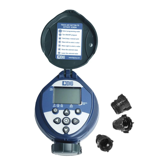
3. COMPONENT IDENTIFICATION 1. Controller cover 2. Quick reference label 3. LCD Display displays the icon-based applications/ programs 4. 7 button programming keypad: Use for programming, system on/off, manual run and reviewing program 5. Battery compartment cap for two AA alkaline batteries (not included) 6. -
Page 5: Lcd Display And Controls
4. LCD DISPLAY AND CONTROLS LCD Display 1. Time and Date Icon – Indicates current time and day is displayed 2. Sensor Icon – Appears when a rain sensor is active or when yellow wire loop has been cut and watering is halted 3. -
Page 6: Installing The Batteries
Control Buttons Select programming mode Turn program(s) ON/OFF Battery replacement Start/stop a manual cycle Move left/right to select a value Raise/lower the selected value 5. INSTALLING THE BATTERIES 1. Open the battery compartment cap by turning it counter-clockwise. 2. Install two, fresh, brand name, AA alkaline batteries (not included) and note the proper direction of the positive and negative orientation on the... -
Page 7: Valve Adapter Installation
4. Screw the solenoid adapter into the valve bonnet by hand, tighten with pliers if necessary – but do not over tighten. 5. Thread the 400A Series solenoid into the valve adapter. Hand tighten only. 6. Turn the main water supply on and pressurize the valve; the valve may discharge water momentarily but should then shut off. - Page 8 CHART A Model Compatible Valves BERMAD series 200, HIT series 500,DOROT series 80, 30 - 920* GRISWOLD series2000, DW and BUCKNER series VB valves 30 - 921 RAIN BIRD DV, DVF, PGA, PEB ( 1” only ) ,GB, EFB - CP, BPE, PESB ( 1”...
-
Page 9: In-Line Valve Installation
7. IN-LINE VALVE INSTALLATION 400A-XXX Rated operating pressure: 10-125 PSI Recommended Operating Pressure: 10-80 PSI Warning: Wrap all fittings with Teflon tape! Do not use pipe cement on valve as this will damage the valve and void the warranty! 1. Shut off main water supply. 2. -
Page 10: Programming
In cyclical mode the 400A Series can also operate from every 1 hour up to every 12 hours or from once a day up to every 30 days. The 400A Series has four start times per day and durations from 1 minute up to 5 hours and 59 minutes. - Page 11 2. If the current time has not been set or needs to be updated press and the hour digit starts flashing. 3. To set the current hour, press (note AM and PM designations). 4. To set the minutes, press again and the minute digit starts flashing. Press to set the current time in minutes.
-
Page 12: Setting Watering Day Schedules
10. SETTING WATERING DAY SCHEDULES Option 1 – Setting Specific Days of the Week: This setting determines which days the 400A Series controller will operate. Choose either watering on specific days of the week, EVEN/ODD days or cyclical from daily up to once every 30 days. - Page 13 and the underscore under Sa (Saturday) starts flashing. 8. Press and the underscore under Sa disappears. Saturday is de-selected. 9. Press Option 2 – Setting Even or Odd Days: To select EVEN days, ODD days refer to the example. Example: setting the controller to water on ODD days 1.
- Page 14 Press the button to proceed to the next step START TIME or to review the program. Option 3 – Setting every X hours: Example: setting the controller to water every 7 hours 1. Press the button until the icon and the days of the week appear. 2.
-
Page 15: Setting Watering Start Times
11. SETTING WATERING START TIMES The 400A Series controller can have up to four separate irrigation start times per day. (Note: if the controller is set to water every X hours, only one start time is available to be programmed.) To set a start time, 1. - Page 16 2. Press and OFF (or the first start time programmed) begins flashing. 3. To set the desired first start time hour (note AM and PM designations), press 4. Press and the minutes start flashing. 5. Press and set the desired start time minutes. 6.
-
Page 17: Setting Watering Run Times (Program(S) Duration)
12. SETTING WATERING RUN TIMES (PROGRAM(S) DURATION) This setting determines the length of time the 400A Series controller will allow the valve to remain open (duration is from 1 minute up to 5 hours and 59 minutes). For example, setting watering run time to 10 minutes on certain days of the week will program the controller to turn the water on for 10 minutes on each of the days chosen and at every start time selected. -
Page 18: Setting Rain Delay - Optional Feature
4. If only watering duration in minutes is required, press to skip the hour digit, and the minutes will start flashing. 5. To set the desired watering duration in minutes (example of 10 minutes), press to select minutes. When programming the watering duration, if you are set to water on specific days of the week, the screen will also show the days the controller will operate with an underline. -
Page 19: Manual Watering
2. Press the button and OFF starts flashing. 3. To set the desired temporary suspension of the program (1-99 days), press 4. The temporary suspension of the program can be cancelled at any time by re-entering Rain Delay screen and changing the setting to OFF. (Press until OFF appears.) Note: OFF appears in between numeric value of 99 and 1. - Page 20 The controller will open the valve and in 5 seconds a count down of the remaining irrigation duration appears, showing when the controller will close the valve. 2. Press the button to end manual run. 3. After 5 seconds the display will revert to the current time screen. To activate a manual watering without the use of the controller –...
-
Page 21: Connecting A Rain Sensor
15. CONNECTING A RAIN SENSOR Most “normally closed” rain sensors can be connected to the 400A Series controller. The function of the sensor is to prevent automatic watering by the set program due to excessive rainfall. To connect the sensor to the controller, please follow these steps: 1. -
Page 22: Changing The Batteries
16. CHANGING THE BATTERIES The 400A Series controller’s batteries can last up to 3 years when using name- brand AA alkaline batteries. Actual battery life will depend on the sensitivity of the installed batteries to temperature ranges experienced by the controller as well as the number of valve operations programmed per day. - Page 23 SOLUTION: Verify that the controller does not show OFF in current time mode CAUSE: AM/PM not set correctly in current time mode SOLUTION: Check current time, change AM/PM if necessary CAUSE: AM/PM not set correctly in start time mode SOLUTION: Check start time(s), change AM/PM if necessary CAUSE: Rain delay is preventing watering SOLUTION: Set rain delay to off CAUSE: Yellow sensor wires have been cut...
- Page 24 PROBLEM: Rain sensor does not prevent watering CAUSE: Rain sensor is normally open, malfunctioning, or not wired correctly SOLUTION: Verify that sensor icon appears on display when pin is pushed down and check all wire splices PROBLEM: Controller waters more than once per day CAUSE: More than one start time has been programmed SOLUTION: Change start time 2, 3, 4, and 5 to OFF...
-
Page 25: Warranty
Repair of damaged units not otherwise within warranty may be refused or done at a reasonable cost or charge at the option of DIG CORPORATION. This warranty gives you specific legal rights, and you may also have other rights, which vary from state to state. -
Page 26: Technical Assistance
DIGPRO Technical Service USA ™ DIG’s Technical Service Team is available to answer questions in English and Spanish from 8:00 AM to 5:00 PM (PST) Monday-Friday (except holidays) at 800-344-2281. Questions can be e-mailed to questions@digcorp.com or faxed to 760-727-0282. -
Page 27: To Order Replacement Or Spare Parts
20. TO ORDER REPLACEMENT OR SPARE PARTS: PLEASE ORDER ONLINE AT WWW.DIGCORP.COM We at DIG Corporation understand that most dealers do not carry spare parts. For your convenience, if you need one of these parts, please order online at www.digcorp.com. - Page 28 Website: www.digcorp.com e-mail: dig@digcorp.com 26-230 REVC 010720 1210 Activity Drive Printed in the USA Vista, CA 92081-8510, USA DIG is a Registered Service Mark of DIG Corp.
Need help?
Do you have a question about the 400A Series and is the answer not in the manual?
Questions and answers