Sign In
Upload
Download
Table of Contents
Contents
Add to my manuals
Delete from my manuals
Share
URL of this page:
HTML Link:
Bookmark this page
Add
Manual will be automatically added to "My Manuals"
Print this page
×
Bookmark added
×
Added to my manuals
Manuals
Brands
DIG Manuals
Controller
720A Series
Instruction manual
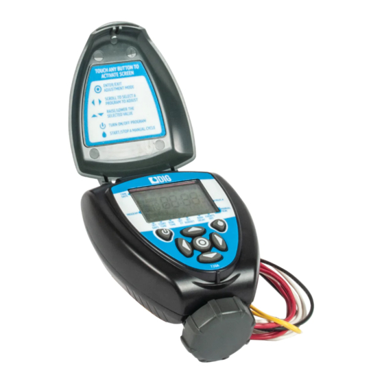
DIG 720A Series Instruction Manual
Two, four and six station irrigation battery operated controller
Hide thumbs
1
Table Of Contents
2
3
4
5
6
7
8
9
10
11
12
13
14
15
16
17
18
19
20
21
22
23
24
25
26
27
28
29
30
31
32
33
34
35
36
page
of
36
Go
/
36
Contents
Table of Contents
Troubleshooting
Bookmarks
Table of Contents
Table of Contents
1 About the Controller
Introduction
2 Component Identification
3 Valve or Wall Mounting
4 Controller Wire Connection
5 Battery Installation
6 Installation Recommendations
DC Solenoid Only Installation
In-Line Valve Installation
Anti-Siphon Valve Installation
DC Actuator Installation
7 LCD Display Icons & Symbols Identification
8 Controller Buttons Identifications
9 Programming
Setting Time and Date
Selecting a Program
Setting Frequency
Setting Start Times
Setting Watering Run Times
Setting the Simplesmart™ Option (Set Et)
Setting Seasonal Adjustment (Monthly Budget)
Rain Delay Mode
Events off Setting
10 Manual Watering
11 Connecting a Rain Sensor
12 Maintenance, Troubleshooting and Repairs
13 Technical Assistance
14 Warranty
Advertisement
Quick Links
1
About the Controller
2
Controller Wire Connection
3
Programming
4
Setting Time and Date
5
Selecting a Program
6
Manual Watering
Download this manual
7X0A
Two, Four and Six Station Irrigation
Battery Operated Controller
720A-XXX | 740A-XXX | 760A-XXX
I N S T R U C T I O N
M A N U A L
Table of
Contents
Previous
Page
Next
Page
1
2
3
4
5
Advertisement
Table of Contents
Need help?
Do you have a question about the 720A Series and is the answer not in the manual?
Ask a question
Questions and answers
Related Manuals for DIG 720A Series
Controller DIG 7001 User Manual
Battery operated irrigation controller with hose or pipe thread (6 pages)
Controller DIG 7001 Instruction Manual
Battery operated irrigation controller with hose or pipe thread (10 pages)
Controller DIG 710 Series Instruction Manual
Single and four station battery operated controllers (11 pages)
Controller DIG 740 Series Instruction Manual
Single and four station battery operated controllers (11 pages)
Controller DIG Irrigation-Mart 710 Series Instruction Manual
Single, four & six station battery operated controller (22 pages)
Controller DIG 710AP Series Instruction Manual
Single station propagation and irrigation battery operated controller (28 pages)
Controller DIG 710A Series Instruction Manual
Single station irrigation battery operated controller (36 pages)
Controller DIG 740A Series Instruction Manual
Two, four and six station irrigation battery operated controller (36 pages)
Controller DIG GQ-AC4 Instruction Manual
Indoor mounting ac irrigation controllers (24 pages)
Controller DIG LEIT-1 Instruction Manual
Ambient light powered, smart irrigation controller (28 pages)
Controller DIG RBC 7000 Instruction Manual
Battery powered in-line valve with watering timer (26 pages)
Controller DIG RBC MVA Instruction Manual
Battery powered actuator with watering timer (15 pages)
Controller DIG LEIT-2 Operating Instructions Manual
2-way radio controller (12 pages)
Controller DIG 410BT Series Instruction Manual
Bluetooth battery powered irrigation controller (12 pages)
Controller DIG 400A Series Instruction Manual
Single station irrigation battery operated controller (28 pages)
Controller DIG 5006-I Owner's Manual
Irrigation controllers (2 pages)
This manual is also suitable for:
740a series
760a series
Table of Contents
Print
Rename the bookmark
Delete bookmark?
Delete from my manuals?
Login
Sign In
OR
Sign in with Facebook
Sign in with Google
Upload manual
Upload from disk
Upload from URL


Need help?
Do you have a question about the 720A Series and is the answer not in the manual?
Questions and answers